Metallkraft HLS 65 S User manual

HLS 65 S
Operating Instructions
HLS 65 S
Hydraulic hole punch
HLS 65 S

Imprint
Product identification Hydraulic hole punch
HLS 65 S Item number: 381 8065
Manufacturer Stürmer Maschinen GmbH
Dr.-Robert-Pfleger-Str. 26
D-96103 Hallstadt
Fax:
E-Mail:
URL:
www.metallkraft.de
Information about the operating instructions
Copyright information
Genuine operating instructions
Edition: 08.05.2017
Language: English
Author: FL
Copyright © 2017 Stürmer Maschinen GmbH, Hallstadt, Germany.
Stürmer is the sole owner of the content of these operating
instructions. Forwarding and reproduction of this document as well as
use and notifcation of its content is not permitted without explicit
consent. Infringements shall oblige to payment of compensation.
Subject to technical modifications and changes.
0049 (0) 951 96555 - 55

Page
4- 3
5
7
8 - 9
10 - 12
13 - 15
16
17 - 21
22
23
24
25
25
26 - 29
30
31 - 32
33
34 - 35
CONTENTS
General notes
Work Station
Technical Specifications
Transportation
Safety explanations
Operation of the machine
Punching Table
Punching Tools
Electrical Informations
Hydraulic System
Lubrication
Machine Rod and Lever readjustment
Maintenance Table
Optional Punch, DIE and Blade
Special accessories
Hydraulic Plan
Spare Parts Drawing
Wiring Diagram
EU - Declaration of Conformity
Notes
36
37
- 3
-

GENERAL NOTES
1. Introduction
Thank you for choosing this Metal Working Machine. We are proud to have you in our long
list of satisfied customers all over the world.
This User’s Manual is absolutely for your safety and is essential for the machine to have a
long production life. As long as you keep up with our Manual you will be able to run your machine
smoothly and safely. Keep in mind that the machine is designed absolutely to perform maximum safe-
ty and for efficient working.
In this Manual you can find instructions and information about:
Correct installations of the machine
Description of the functional parts of the machine
Set-up and start-up adjustments
Correct standard and scheduled maintenance
Simple safety regulations and accident prevention.
Therefore, as far as the user’s safety is concerned, in this handbook the possible risks con-
nected with machine operation are pointed out as follows:
Attention: Showing the risks of accident, if instructions are not followed.
Warring: Showing the probable damages to the machine or equipment, if the in-
structions are not strictly followed.
Note: It gives useful information.
It is certainly necessary that the operator should read and understand all the Attention, War-
ring,Note specified in this Manual before starting with operation of the machine and before any lubri-
cation or maintenance intervention
On all steps of installation, operation and maintenance safety must be your first concern for
the protection of yourself, other users and the service of the machine. In case of any failure please first
refer to this Manual, and then if a solution cannot be found contact first of all the distributor where you
purchased our product. Do not forget to refer to the drawings and the numbers for any spare part
needed or to define any problem. Make sure you have the serial number and production year of the
machine.
Our technical staff will make their bestto help you in the most convenient way.
-4
-

2. Transport
As soon as you receive the machine, check for any visible transport damages. Should there be any
visible damages; report it straight away to the transporter company and of Stürmer Maschinen
GmbH.
Remove any protective crates around the machine and read the instructions on related chap-ters of
this Manual carefully to set up the machine. If the machine is damaged while transport, immediately
take some photographs for insurance claims.
Take precautions while loading / unloading or moving the machine to avoid any injuries. Refer also to
related chapter of this Manual for the best way of handling the machine.
3. Electrical Information
All necessary connection procedure can be found on this Manual. Do not try to connect the
machine before reading these procedures and fully understanding the drawings. For any unclear mat-
ters get in touch with us or our distributors. Have the machine connected by a qualified electric techni-
cian. For, as we made clear in the “general conditions of guarantee”, under no circumstances installing
mistakes, including electrical connection mistake, can not be covered by guarantee agreement. Al-
ways turn off power before making any connections or disconnecting the machine.
4. Maintenance
Your machine is designed and produced to work efficiently and smoothly. To achieve this you should
also take care while operating the machine. Regard Maintenance sections to have the longest life
from your machine. Try and use original spare parts where necessary and most importantly do not
overload the machine or do not make any unauthorized modifications.
5. Safety
Take all precautions possible to avoid any personal injury while using the machine. Keep in mind to
protect the third party people around the machine. Refer tosafety directives.
-5
-

WORK STATION
PUNCHING STATION
All punching operating are processed by means ofhydraulic power thus giving the machine the ability
to punch very efficiently and silently. Itcan either be used to punch thick materials or thin materials in
layers together. Punching is silent, powerful, efficient. The waste materials in layers together. The
punching table consists two parts. First isthe punching flange. The second is holder. The holder isa
device that holds the material after punching not to come back with the punch. Itmust be equally
adjusted or itcan break the punch. There are different holders for different materials. However the
standard holder which we supply issuitable for punching is between 6-38 mm.
SAFETY PRECAUTIONS
All power and depth and other adjustment must be done under full control of an
experienced technician
Please check all the moving parts before working
Check the punch and die that they are in the same direction
Adjust the holder equally and according to the material
Always use the protective plastics
On small and accuracy needing works use special protection
While replacing the punch or die or holder shut the main switch
Never leave the machine unattended
Do NOT overload the machine
WORK STATION
-6
-

Technical specifications
Pressure
Ø in max.sheet thickness
Reach
Stroke
Stroke / min.
65 t
Ø26x20 mm / 57 x 10*** mm
625 mm
55 mm
22 min-1
Hole punch working height 950 mm
Motor output 5,5 kW
Electrical connections 400 V / 50 Hz
Dimensions in mm 1600x900x1800
Weight 2440 kg
Based on material strength 45 [kg/mm2]
The maximum punching pressure of this machine is 650 kN ( 65 ton )
The following tools are included inthebasic equipment of the machine;
Punch mount with bayonet closure
Punch and die reducers
No. 1, 2, 3, 30, 45, 60
Stop with scale
Work light
Foot pedal
Hook wrench
Hydraulic oil
-7
-
ADDITIONAL TOOLS
BENDING
Maximum bar size
Maximum sheet metal size 250x15 [mm]
500x3 [mm]

TRANSPORTATION
There is a ring mounted on top of the machine for transport purposes. You mount the chain or
rope to this ring for all kind of displacement purposes.
a) Visible mounted tools
b) Tools in the
c) Safety guards
d) Oil gauge
e) Main power knob
f) Foot pedal cable
Attention:
If you see any visible damage on electric components, do NOT connect the machine to power.
Inform the manufacturer as soon as possible. Ask a qualified electric engineer for connecting the
machine. Stürmer Maschinen GmbH WILL NOT BE RESPONSIBLE FOR
DAMAGE CAUSED BY IMPROPER CONNECTION OF ELECTRICS.
-8
-
DAMAGES
As soon as you receive the machine, make a general check on the machine and inform the
transporter and the manufacturer in case of any visible damage. Especially be careful on
these points;

SETTING UP THE MACHINE
Ask for help of an experienced and qualified technician while setting up the machine
1-) Fundamental Plan of the Machine
5 holes ( Refer to the drawing below ) Dia : 15 mm
2-)Instructions
For an effective machine, the position and the base of the machine are important. Be careful on
these points while placing the machine:
The machine must be placed on a flat, preferably cement base. To fix the machine use bolts.
There must be plenty of room all around the machine for easy working.
The machine height is ideal for any workingman.
There must be plenty of Light on top of the machine
-9
-

SAFETY EXPLANATIONS
The HLS-65 Sis equipped with ahydraulic check valve system in order to relieve the
excess pressure when the machine is overloaded, thus preventing serious damage to the machine
and the worker. All safety precautions are for your safety, which we believe will be obeyed by our
customers unasked.
SAFETY UNITS
Quick stop button use on the panel and main body
Protective barriers
In this manual are summarized the important information for work safety. The following
security explanations and instructions are considered as the essential information for your safety. Any
and all persons who must operate the machine should be firstly trained well in terms of the operation
and safety information and instructions. For this purpose, more copies of this manual shall always be
asked from the supplier. It should be clearly fixed out that which persons will have the responsibility to
change and arrange tools. These persons need to be essentially trained in terms of this subject.
All the machines are delivered as standard with a safety equipment, such equipment is for a
high and general work safety. For this purpose, the machine should only be used in accordance for
those purposes for which it has been constructed.
The most dangerous and probable deviations as to the construction limits of the
machine are estimated to be as follows:
1. Machining of other materials as unalloyed steel (45 kg/mm2)
2. Erroneous use of the fixing installation
3. Punching or fixing very small work pieces, as these will easily cause the operators be subject
to danger zones.
Should the additional tools be necessary to be used on the machine, which are not foreseen
by the producer, it should be re-verified whether or not there is sufficient safety and security against
work accidents. For this purpose, the producer should be contacted for advice when deemed
necessary. All the maintenance works should be carried out by sufficiently qualified expert personnel.
Particular attention should be paid to the correct assembly and arrangement of the hole stamps,
cutting cases and other tools. In order to enable us and yourselves to fulfill our mutual and common
responsibility for all people, we request you to read this manual very carefully before putting the
machine into operation and to obey all the safety information and instructions.
Attention: ALL THE PARTS OF THE MACHINE DYED IN RED ARE DANGER ZONES AND
PARTICULAR ATTENTION SHOULD BE PAID IN SUCH ZONES !
All the operators should be instructed in order not to place their fingers or other body parts
near, in or under the parts of the machine colored in red. There is the risk of losing the body parts
when these are placed in such zones !
-10
-

All the safety components and fixing installations that should be removed for maintenance
purposes, should be remounted again before the machine is reoperated. The operators should wear
the clothing described by the employer. The producer recommend the use of protection eyeglasses
against eventual stamp breaks and shoes with steel covering in order to prevent foot of the operator
against falling materials.
SAFETY RULES
1. The assembly and adjustment works, tool changes and maintenance services shall only be
realized by the technical personnel qualified for this purpose, who should strictly obey the
instructions of the producer.
2. Remove any oil remaining, cuttings and other impurities from the working zone where such
remaining might be left the previous operator.
3. Before the starts working on the machine, the operator should make sure that all the tools are
in a perfect condition.
4. Any leakage and order of hole stamps should be checked after each tool change and be
readjusted if necessary.
5. The scraper should always be adjusted according to the material resistance to be machined.
Unequal scraping forces can easily result with tool breaks.
6. Never punch any material which stronger than the diameter of the hole stamp. In this case, the
hole stamp can be overloaded and easily break.
7. Always punch trough holes. Never punch base holes, unless the tool is clearly foreseen for
this purpose. The lateral elongation force, which occurs during punching of the base holes,
might excessively press the hole stamp against the cutting case and consequently an easy
break might result.
8. The machine has been designed in a manner to work with the pieces which can be placed
without having subjected the fingers or hands into the danger zone. For punching of the short
pieces ( for instance small sheet metal parts ), special tools, scrapers and security
components are pieces should be placed into the machine and taken back suitable holding
tools.
9. Before each tool change, make sure that the machine is disconnected from main switch.
10. Completely disconnect the machine from the net before you carry out any maintenance work.
11. Never let the machine function without any inspection.
12. When you perform works where big forces are existing, the work piece should be additionally
protected through a block having an assembled roll or similar installation, which is to be
placed on the machine.
-11
-

13. The machine capacity shall never be exceeded. For this purpose, check the" technical data"
on this rules and compare the values with the information given on the manufacture plate. All
the capacity information is based on a material having a resistance of 45 kg/mm2
14. Should the hydraulic circuit flow be overloaded, the hydraulic oil will be led back to the reserve
tank over the overload valve until the pressure gets down again to the normal level.
Attention: HOWEVER, IT IS. NECESSARY TO UNDERLINE THAT IT MIGHT BE
DANGEROUS TO USE THE OVERLOAD VALVE AS A " SAFETY VALVE " IN ORDER TO
EXCEED THE MACHINE CAPACITY.
The producer presents all the instructions for a work protection and safety and hopes to have
a good and full calibration with you, the users, in order to ensure that the maximum Level of safety
could be obtained.
CONTROLS BEFORE PUTTING INTO OPERATION
1. Press on the green " START " button in order to start the machine. In order to ensure this,
make sure that the red off button ( " STOP" ) rotates clockwise (or directly to draw).
2. Make sure that the entries for hole stamp is safety fixed.
3. At the command table, change the status from " NORMAL" to " ADJUSTMENT " ( Consider
that the readjustment course is not automatic at this position. When you leave the foot pedal
loose, the machine does not return to standby, rather it simply gets left).
4. Make sure that the course limiter allows a maximum course. Now, press on the foot pedal so
often that the hole stamp stays in the cutting case. Take care that the hole stamp is regularly
arranged with the cutting case.
5. Change the position from “ADJUSTMENT” to “NORMAL” at the command board. Now the
machine gets automatically back to the standby position.
6. Check whether or single cylinder perform, full course. Make sure that, no-hydraulic pres-sure
occurs at the and of related course. In order to ensure that there is no air available in the
hydraulic system, repeat the process several times (air might enter here during transport).
7. Verify all tubes, hoses connections, branching and reserve tank for eventual hydraulic
leakage.
8. Fix again all the protection parts and remove all loose subjects from the working zone of the
machine
The machine is now ready for your job.
-12
-

OPERATION OF THE MACHINE
Operation elements
All the electrical delivery of the machine passes through the main switch. In order to connect this,
rotate the switch clockwise. To confirm this, check that the control lamp starts lighten.
By pressing on the green “START” button, connect the motor ( for the motor to be able to
function, the “STOP” button should be disconnected. This can be realized by rotating the red button
clockwise ( or drawing this ).
By pressing on the red “STOP” button, the motor will be stopped. The lightly pressed “STOP” button
gets locked at command. Inorder toloosen the button and to cause the machine to function again, the
“STOP” button will be turned clockwise ( or drawn ).
The pedal switch has three positions:
Over position
central position
lower position
If pedal is driven till the lower position and there remains fixed, the machine gets into the
deepest punching position. Nevertheless, the machine doesn’t turn back to the standby position until
the pedal is left loose.
The central pedal position allows the operator to effect unlimited positioning including over and
down course. This central position is very practical because it allows the operator to carry out touching
so that the work piece can be optimally positioned.
The switch “NORMAL / ADJUSTMENT” ensures that the machine is operated at touch
operation or performs production at normal functioning.
When the switch is arranged on “NORMAL” , the machine performs a normal and full work
cycle at each action of the foot pedal, that means the punch moves to the lowest position and then
gets again into the standby.
When the switch is arranged to “ADJUSTMENT” the machine stops. When the pedal is left loose, the
automatic back course at this position has been cancelled.
-13
-
STROKE ADJUSTMENT
In order to lock the lowering stroke ( that means repeated bending
etc. ) you must adjust the stopper A towards side.
In order to lock the upper stroke B, use the punch stamp with the
foot pedal and hold this in the lower position. Now lift the foot up
in order to verify the position. If necessary, a readjustment shall
be foreseen now.
Attention :
All the adjustments to be made on the stroke limiter, can also be
carried out by using, the leading mode. For this purpose, the
punch position is arranged in such a manner that the required
position is obtained by the foot pedal and then the stoppers are
adjusted upon request. After the adjustment process, you must
cause the machine to function under normal tempo in order check
the stoppers.
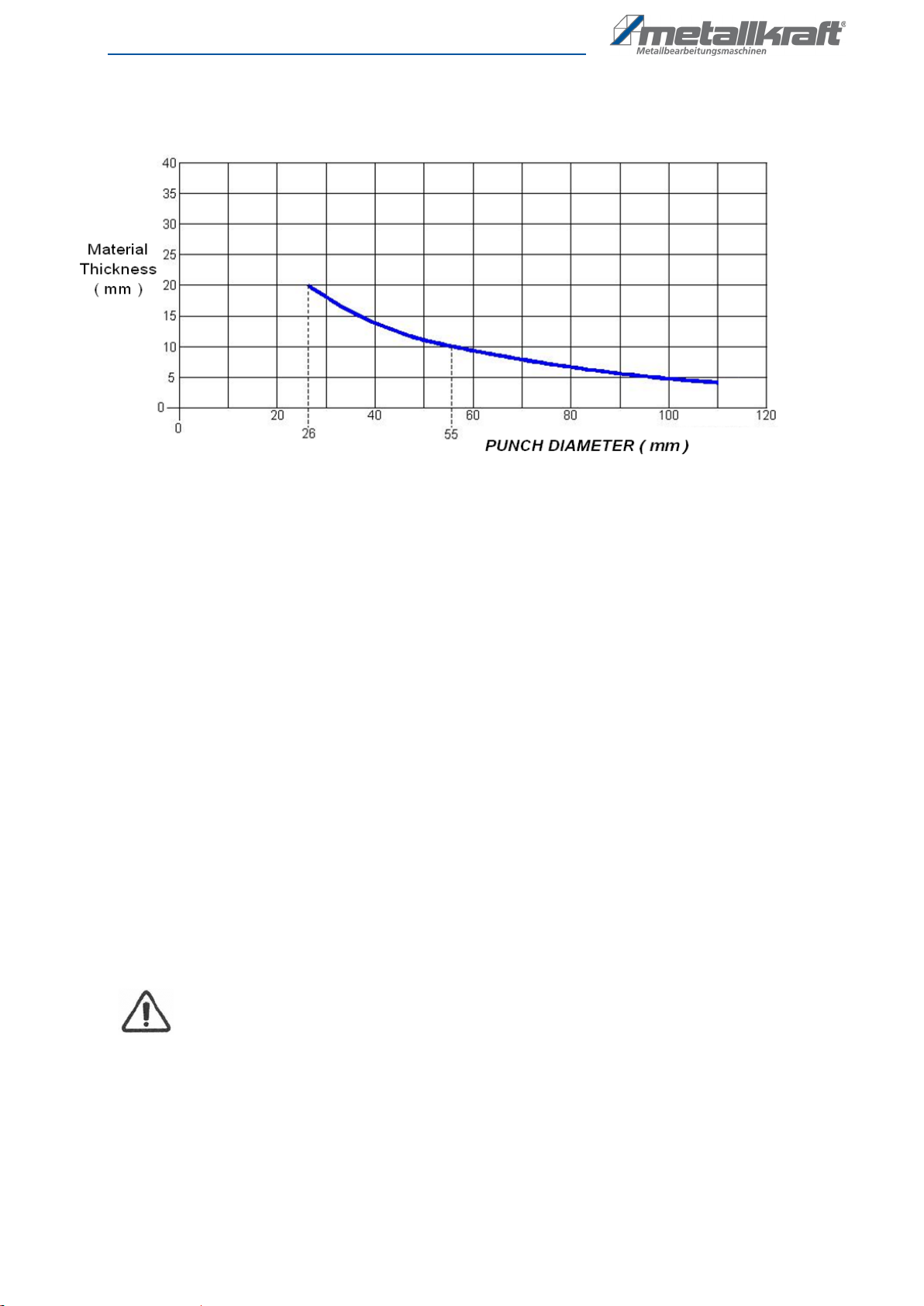
PUNCH CAPACITY
The diagram shows the punch capacity curves of the XS-series depending on the material thickness
and stamp diameter. ( Based on a construction steel having a traction resistance of 45kg/mm2).
Diameter of the punch stamp D (mm). During calculation of the punch capacity it should proceeded
according to the following formula:
P = SHEARING SURFACE x TRANTION RESISTANCE
P = Π x D x S x TRANTION RESISTANCE
A calculation example :
A 20 mm hole will be necessary in a 12 mm thick homogenous steel sheet metal having 45kg/mm2
traction resistance
This is valid the following:
Punching pressure = Shearing surface x traction resistance x 0.0098 and
Shearing surface = Volume of the punch stamp x material thickness ( so the traction resistance
Amounts to 45kg/mm2, 0.0098 is the fixed value for the calculation of kg/mm2 on KN
accordingly : 20x 3,142x12x45x0,0098 = 333 KN ( 33,3 Tons )
Attention :
Never punch with a hole stamp which is thinner than the material to be machined.
-14
-

PRESS BRAKE BENDING
Bar bending max. Capacity 250 x 20 mm
Sheet bending max. Capacity 500 x 3 mm
PIPE NOTCHING
Max. Pipe diameter is Ø 108 mm
-15
-

PUNCHING TABLE
In order to break the punching tool, you must use this table ( holder ) wisely. It must be always
equaled and must be set for different pressures. The distance between lower table and material
should be something between 1- 3 mm. Also to have the tool efficiently work the biggest part of the
material should be covered by lower body during operation.
-16
-

PUNCHING TOOLS
The part numbers in the above given figure 1 belong to the standard equipment.
-17
-

The parts indicated in the below given table belong to the standard equipment. Some different
hole stamps and cutting cases are illustrated on the lateral drawing.
As standard material, a 22 mm hole and cutting case delivered ( the maximum diameter
amounts to 38 mm ). Adjust the hole stamp centrally so that an equally rotating cutting distance of 5 %
of the material thickness remains. Never punch a material that is thicker than the diameter of the hole
stamp.
Assembly
No
Quantity
Part Identification
1
1
Pressrue plate
2
1
Passing spring
3
1
Hole stamp
4
1
Adapter
5
1
Holding ring
6
1
Top scraper plate
7
1
Lover table
8
2
Spring
9
1
Washer
10
1
Soc. head cap bolt
11
1
Washer
12
1
Soc. head cap bolt
13
2
Washer
14
2
Spring
15
2
Spring washer
16
2
Support tensioning
17
1
Tension plate
LUBRICATION OF THE PUNCH TOOLS
In order increase the service lives of the hole stamp and cutting case, we recommend you to use one
of the below listed lubrications;
Shell Garia 927
BP Servora 68
Castroll llobroach 219
Duckharns Adfomol EP7
Joseph Batson LB 733
-18
-

ARRANGEMENT OF THE PUNCH TOOLS IN GENERAL
The big punch bearing surface and the
removable front block have been constructed in manner
to allow a very wide range punch works:
Through the optionally obtained tools, the big
holes in any form up to the diameter / quadrate as it is
indicated in the capacity table can be produced. In
addition, machining at overhanging position, with the
removed front in addition, during machining at overhang,
with the removed front block, the of U profiles of double
T supports having diameters or eventually diagonals up
to 38mm highest capacity can be punched.
The punching stamp is held though a holding
ring, according to the size of the stamp ( punch ) one or
two of the delivered adapters can be used. The matrixes
are fixed to the tensioning plate through a positioning
screw. When the filled punch stamps and matrixes are
be arranged, it should be paid attention to the screw is
correctly placed on the machined surface of the matrix.
In order to allow a suitable play area and to ensure that
the material is taken out, the punch stamp scraper plate
should be correctly adjusted, however it should not effect
the stamp course. Attention should be paid to that the
lower course limiting switch has been adjusted as per the
instructions. When the holes are punched with sufficient
material, a flat contact occurs at both sides of the
scraper plate. The scraper forces can be important and
unbalanced scraper forces can lead to the break of the
punch stamp through the contact with a side of the
scraper.
No material should be punched which is thicker
than the stamp diameter. The quality of the hole is a
direct finger appearance on the situation of the punch
stamp and matrix.
When the scraper fingers are used for very big
holes or irregular forms, the fingers should be equally
position and adjusted in order to prevent and unbalanced
scraper load.
Additional tools at this multi purpose work
station allow bar and sheet metal bending works, edge
threading, tube threading and general column positioning
works.
-19
-

In order to install or change the punch tools you will need the following tools:
Hook key
Soc. head cap bolt key ( 6 mm )
Screw key ( 24 mm )
Below we explain step by step now the hole stamp and cutting case are changed :
1) In order to take out the cutting case, move the machine to a position where there is enough
2) Disconnect the machine at machine switch
3) Open the scraper, loose the coupling nut, fixing screws of the cutting case delivery plate and the
M12 screws, which hold the cutting case. Remove the coupling nut together with the hole stamp
and adapter. Remove the cutting case.
4) Place the required punch tool set. Make sure that the hole stamp and cutting case are correctly
fixed.
5) Connect the machine and than position at “adjustment”.
6) Move the hole stamp slowly towards the cutting case. Push the cutting case delivery plate
correctly so that the hole stamp and cutting case are completely arranged.
7) Adjust the cutting case delivery plate in a manner that the cutting distance which remains
between the hole stamp and cutting case is fully equal and draw the delivery plate fixed in this
station.
8) Take the scraper back then adjust the distance between the scraper and cutting case according
to the thickness of the material to the machined.
9) Adjust the course adjustment in such a manner that the shortest possible way should be left
back.
10) In order to protect the operations, fix the macralon protection before you start working.
WHILE ORDERING SPARE STAMPS AND MATRIXES, PLEASE ALWAYS INFORM OF THE
FOLLOWING : MODEL, TYPE AND MANUFACTURING NUMBER OF THE MACHINE.
-20 -
This manual suits for next models
1
Table of contents
Other Metallkraft Power Tools manuals


Popular Power Tools manuals by other brands

Draper
Draper 55742 user manual

Campbell Hausfeld
Campbell Hausfeld AF010800 operating instructions

Craftsman
Craftsman 315.172320 owner's manual

Campbell Hausfeld
Campbell Hausfeld AF010600 operating instructions

Makita
Makita 6918D instruction manual

GÜDE
GÜDE GRW 1800 Translation of the original instructions


