SGS GPB260 User manual

FOR YOUR SAFETY
PLEASE READ THESE INSTRUCTIONS CAREFULLY
AND RETAIN THEM FOR FUTURE USE.
OWNER’S MANUAL
GPB260
LEAF BLOWER & VACUUM
No

PAGE 3
PAGE 2
SPECIFICATION
MODEL No GPB260
ENGINE SIZE 25.4 cc
POWER 0.75KW / 1HP
MAX AIR SPEED 225kph / 140mph
FUEAL TANK CAPACITY 400cm3
AIRFLOW VOLUME 0.17m3/s
WEIGHT 4.7 kg
WARNING
Read and understand the instruction manual before
using the blower. Restrict unit to users who understand
and will follow all warnings and safety rules in this
manual.
Approved protective goggles or visor, ear protection,
gloves, and face mask in dusty environments must be
worn.
WARNING: This blower can be dangerous! Careless
or improper use can cause serious or even fatal
injury.
GENERAL SAFETY PRECAUTIONS
WARNING: Be sure the bottom cover is secured or the
vacuum tube is properly installed. Avoid the impeller
blade with your hand or any foreign object.
WARNING: The blower may throw objects at high
velocity that can ricochet and hit the operator.
WARNING: The muffler is very hot during and after use.
Do not touch the muffler, muffler guard, or surrounding
surfaces and do not allow combustible material such as
dry grass or fuel to do so.
When using the vacuum attachment the unit is designed
to pick up dry material such as leaves, grass, small twigs,
and bits of paper. Do not vacuum stones, gravel, metal,
broken glass, etc, to avoid severe damage to the
impeller.
Keep children, bystanders, and animals away from work
area at a minimum of 15 meters when starting or operat-
ing unit. Do not point blower nozzle in the direction of
people or pets.
Only use unleaded petrol and two stroke oil.
WWW.SGS-ENGINEERING.COM

PAGE 5
PAGE 4
• Always wear eye and ear protection when operating, servicing, or
performing maintenance on unit. Wearing eye pretection will help to
prevent rocks or debris from being blown or ricocheting into eyes
and face which can result in blindness and/or serious injury.
• Always wear foot protection. Do not go barefoot or wear sandals.
• Always wear a respirator face mask when working with in dusty
environments.
• Secure hair above shoulder length. Secure or remove jewelry, loose
clothing, or clothing with loosely hanging straps, ties, tassels, etc.
They can be caught in moving parts.
• Do not operate unit when you are tired, ill, or if you are under
the influence of alcohol, drugs, or medication.
• Eliminate all sources of sparks or flame (including smoking, open
flames, or work that can cause sparks) in the areas where fuel is
mixed, poured, or stored.
• Mix and pour fuel in an outdoor area; store fuel in a cool, dry, well
ventilated place; use an approved, marked container for all fuel
purposes.
• Do not smoke while handling fuel or while operating the unit.
• Make sure the unit is properly assembled and in good operating
condition.
• Do not fill fuel tank while engine is hot or running.
• Avoid spilling fuel or oil. Wipe up fuel spills before starting engine.
• Move at least 3 meters away from fuel and fueling site before starting
engine.
• Always store petrol in a container approved for flammable liquids.
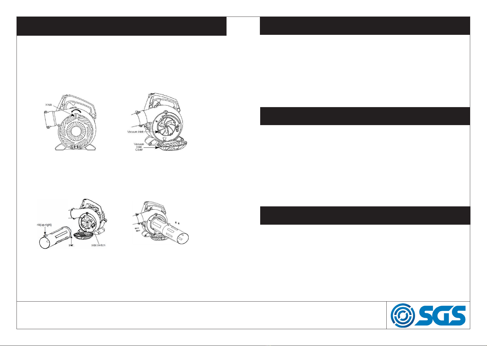
• Stop the engine before opening the vacuum inlet door. The engine
must be stopped and the impeller blades no longer turning to avoid
serious injury from the rotating blades.
• While vacuuming or blowing debris, hold the unit with the muffler
side facing away from your body and clothes.
GENERAL SAFETY PRECAUTIONS GENERAL SAFETY PRECAUTIONS
• Inspect unit before each use for worn, loose, missing, or damaged
parts. Do not use until unit is in proper working order.
• Keep outside surfaces free of oil and fuel.
• Never start or run engine inside a closed room cr building. Breathing
exhaust fumes can kill.
• Mufflers fitted with catalytic converters get very hot during use and
remain so for some time after stopping. This also applies at idle
speed. Contact can result in burns to the skin.
• To avoid a static electricity shock, do not wear rubber gloves or any
other insulated gloves while operating unit.
• Do not set unit on any surface except a clean, hard area while
engine is running. Debris such as gravel, sand , dust, grass, etc. could
be picked up by the air intake and thrown out through discharge
opening, damaging unit, property, or causing serious injury to by
standers or operator.
• Avoid dangerous environments. Do not use in unventilated areas or
where explosive vapors or carbon monoxide build up could be
present.
• Do not overreach or use from unstable surfaces such as ladders, trees,
steep slopes, rooftops, etc.
• Never place objects inside the blower tubes. The force of air can
cause rocks, dirt, or sticks to be thrown or to ricochet.
• Never run unit without the proper equipment attached.
• Check air intake opening, blower tubes, vacuum tubes, and elbow
tube frequently, always with engine stopped and spark plug discon
nected. Keep vents and discharge tubes free of debris which can
accumulate and restrict proper air flow.
• Never place any object in the air intake opening as this could restrict
proper air flow and cause damage to the unit.
• Never use for spreading chemicals, fertilizers, or ether substances
which may contain toxic materials.
WWW.SGS-ENGINEERING.COM

PAGE 7
PAGE 6
ASSEMBLY: VACUUM
1. Open the zipper on the vacuum bag and insert the elbow tube.
2. Push the small end of the elbow tube through the small opening in the
bag. Make sure edge of the small opening is flush against the flared area
of the elbow tube, and the rib of the elbow tube is on the bottom.
3. Close the zipper on the bag. Make sure the zipper is closed completely.
4. Remove blower tubes from engine.
5. Insert the elbow tube into the blower outlet. Make sure elbow tube rib is
aligned with the blower outlet clamp bolt (upper).
6. Secure the elbow tube by turning the bolts clockwise.
1. Align the rib on the upper blower tube with the clamp bolt (upper) in the
blower outlet, slide the tube into place. Tube clamp bolts must be loose
enough to allow blower tube to be inserted in blower outlet. Loosen the
bolt by turning anticlockwise (do not remove nuts).
2. Secure the tube by turning the bolts clockwise.
3. Align the rib on the lower blower tube with the rib on the upper blower
tube.
4. Slide the lower blower tube onto the upper blower tube.
5. Secure the tube by turning the bolts clockwise.
6. To remove the tubes, turn the bolt counterclock wise to loosen the
tubes.
ASSEMBLY: BLOWER
WWW.SGS-ENGINEERING.COM

PAGE 9
PAGE 8
CONVERT UNIT FROM VACUUM USE TO BLOWER USE
1. Remove the elbow tube and vacuum bag by turning the bolts
anticlockwise to loosen the elbow tube.
2. Remove the vacuum tubes by turning the tubes clockwise.
3. Close the vacuum inlet cover and make sure it is latched closed.
4. Reinstall the blower tubes (see BLOWER TUBE ASSEMBLY).
1. Pass the shoulder strap over your head and onto your left shoulder.
2. Extend your right arm toward the rear of the vacuum bag.
3. Adjust shoulder strap until the vacuum bag/shoulder strap seam lies
between your thumb and index finger.
4. Make sure air flows freely from the elbow tube into bag. If bag is kinked,
the unit will not operate properly.
Inspect area before starting unit. Remove all debris and hard objects such
as rocks, glass, wire, etc. that can ricochet, be thrown, or otherwise cause
injury or damage during operation.
This machine produces an electromagnetic field during operation. Under
some circumstances, this field may interfere with active or passive medi-
cal implants. To reduce the risk of serious or fatal injury, we recommend
persons with medical implants to consult their physician and the medical
implant manufacturer before operating this machine.
SHOULDER STRAP ADJUSTMENT
SAFETY BEFORE USING
1. Stop engine and be sure the impeller blades have stopped turning
before opening the vacuum inlet door.
2. Turn the knob anticlockwise untill the knob is loose.
3. Pull up the vacuum inlet cover with your hand. Hold the vacuum inlet
cover open until upper vacuum tube is installed.
4. Align the switch on the inside of the vacuum inlet with the slot on the
upper vauum tube.
5. Push the upper vacuum tube into the vacuum inlet. Turn the tube anti-
clockwise to secure the tube to the blower unit.
6. Align the rib on the lower blower tube with the rib on the upper blower
tube. Slide the lower vacuum tube on to the upper vacuum tube.
7. When vacuum tubes are fitted together assemble the two tubes
together with the supplied screws.
ASSEMBLY: VACUUM TUBE
WWW.SGS-ENGINEERING.COM

PAGE 11
PAGE 10
FUELING ENGINE
•
Remove fuel cap slowly when refueling.
This engine is certified to operate on unleaded petrol. Before operation,
petrol must be mixed with a good quality 2-stroke air-cooled engine oil
designed to be mixed at a ratio of 40: 1
A 40:1 ratio is obtained by mixing 5 litres of unleaded petrol with 0.125
litres of oil. DO NOT USE automotive oil or marine oil. When mixing fuel,
follow instructions printed on oil container. Once oil is added to petrol,
shake the container to assure that the fuel is thoroughly mixed.
CAUTION: Never use straight petrol in your unit. This will cause permanent
engine damage.
Use good quality unleaded petrol. The lowest recommended octane grade
is 90 (RON).
IMPORTANT: Use of alcohol blended fuels (more than 10% alcohol) can
cause major engine performance and durability problems.
WARNING: Incorrect use of fuel and/or lubricants will cause problems such
as: improper clutch engagements, overheating, vapor lock, power loss, lu-
brication deficiency, deterioration of fuel lines, gaskets and internal carbu-
retor components, etc. Alcohol blended fuels will cause a high absorption
of moisture in the fuel/oil mixture, causing the separation of oil and fuel.
OPERATION
• While vacuuming or blowing debris,
hold the unit with the muffler side
facing away from your body and
clothes.
• To reduce the risk of hearing loss
associated with sound level(s),
hearing protection is required.
• To reduce the risk of injury associ-
ated with contacting rotating parts,
stop the engine before installing
or removing attachments. Do not
operate without guard(s) in place.
• Operate power equipment only at reasonable hours-not early in the
morning or late at night when people might be disturbed.
• To reduce noise levels, operate power blowers at the lowest possible
throttle speed to do the job.
• Use rakes and brooms to loosen debris before blowing.
• In dusty conditions, slightly dampen surfaces.
• Watch out for children, pets and open windows. Blow debris away
safely.
• Use the full blower nozzle extension so the air stream can work close to
the ground.
• After using blowers and other equipment, CLEAN UP! Dispose of
debris in trash receptacles.
WWW.SGS-ENGINEERING.COM

PAGE 13
PAGE 12
STARTING THE ENGINE
•
STARTING A WARM ENGINE:
1. Ensure the throttle lock lever is in the vertical position.
2. Move the stop switch to “1” position.
3. Pull starter rope sharply until engine runs.
Warning: Avoid touching muffler unless engine and muffler are cold. A hot
muffler can cause serious burns.
HOW TO STOP YOUR ENGINE:
1. Release the throttle trigger.
2. Push and hold the STOP switch in the STOP position until the engine
stops.
WARNING: Disconnect the spark plug before performing maintenance
except for carburetor adjustments.
STARTING THE ENGINE
•
You MUST make sure the tubes are secure before using the unit.
Hold the unit in the starting position as shown. Make sure the blower end is
directed away from people, animals, glass, and solid objects.
When starting engine, hold the unit as illustrated. Do not set unit on any
surface except a clean, hard area when starting engine or while engine is
running. Debris such as gravel, sand, dust, grass, etc. could be picked up
by the air intake and thrown out through the discharge opening, damaging
the unit or property, or causing serious injury to bystanders or the operator.
STARTING A COLD ENGINE (or a warm engine after running out of
fuel):
1. Ensure the throttle lock lever is in the vertical position.
2. Move the stop switch to “1” position.
3. Slowly press the primer bulb 6 times.
4. Move the choke lever to the “Full” choke position.
5. Pull starter rope handle sharply until engine sounds as if it is trying to
start, but do not pull rope more than 6 times
6. Squeeze the throttle trigger, the choke lever will move to” RUN “choke
position.
7. Pull starter rope sharply until engine runs.
8. Once the engine runs, allow it to run 10 seconds.
WWW.SGS-ENGINEERING.COM

PAGE 15
PAGE 14
MAINTENANCE
REPLACE SPARK PLUG:
Replace spark plug each year to ensure the engine starts easier and runs
better. Set spark plug gap at 0.6 mm. Ignition timing is fixed,
nonadjustable.
1. Twist, then pull off spark plug boot.
2. Remove spark plug from cylinder and discard.
3. Replace spark plug
4. Tighten securely with a 19 mm socket wrench.
5. Reinstall the spark plug boot.
REPLACE FUEL FILTER:
To replace fuel filter, drain unit by running it dry
of fuel, then remove fuel cap/retainer assembly
from tank. Pull filter from tank and remove it from
fuel line. Install new fuel filter on fuel line; reinstall
parts.
CHECK MUFFLER MOUNTING SCREWS:
Once each year, ensure muffler mounting screws
are secure and tightened properly to prevent dam-
age.
CARBURETOR ADJUSTMENTS:
The carburetor has been carefully set at the
factory. Adjustments may be necessary if you
notice any of the following conditions. Engine will
not idle when the thrcttle is released.
IDLE SPEED ADJUSTMENT:
Allow engine to idle. Adjust speed until engine
runs without stalling. Turn idle speed screw clock-
wise to increase engine speed if engine stalls or
dies.Turn idle speed screw anticlockwise to de-
crease engine speed.
MAINTENANCE
CHECK FOR LOOSE FASTENERS AND PARTS:
• Muffler
• Spark Plug Boot
• Air Filter
• Housing Screws
CHECK FOR DAMAGED OR WORN PARTS:
Contact SGS for replacement of damaged or worn parts.
• Fuel Tank. Discontinue use of unit if fuel tank is damaged or leaks.
• Vacuum Bag - Discontinue use if vacuum bag is torn or damaged.
INSPECT AND CLEAN UNIT & LABELS:
• After each use, inspect complete unit for loose or damaged parts. Clean
the unit and decals using a damp cloth with a mild detergent.
• Wipe off unit with a clean dry cloth.
CLEAN AIR FILTER:
A dirty air filter decreases engine
performance and increases fuel
consumption and harmful emissions.
Always clean after every 5 hours
of operation or yearly, whichever
comes first.
Clean the cover and the area around
it to keep debris from falling into
the carburetor chamber when the
cover is removed.
Move choke lever to RUN position
before opening air filter cover. Remove parts as illustrated. Wash the filter
in soap and water. Allow filter to dry.
Apply a few drops of oil to the filter; squeeze filter to distribute oil.
Replace parts.
WWW.SGS-ENGINEERING.COM

PAGE 17
PAGE 16
TROUBLESHOOTING TABLE
WARNING: Always stop unit and disconnect spark plug be-
fore performing any of the recommended remedies be-
low, other than remedies that require operation of the unit.
STORAGE
WARNING: Prepare unit for storage at end of season or if it will not be
used for 30 days or more.
• Allow engine to cool, and secure the unit before storing or transporting.
• Store unit and fuel in a well ventilated area where fuel vapors cannot
reach sparks or open flames from water heaters, electric motors or switch-
es, furnaces, etc.
• Store unit with all guards in place. Position unit so that any sharp object
cannot accidentally cause injury.
• Store unit and fuel well out of the reach of children.
• Remove spark plug and pour 1 teaspoon of 2- stroke engine oil (air
coded) through the spark plug opening. Slowly pull the starter rope 8 to 10
times to distribute oil.
• Replace spark plug with new one of recommended type and heat range.
• Clean air filter.
• Check entire unit for loose screws, nuts, and bolts. Replace any damaged,
broken, or worn parts.
• Start each season using only fresh fuel having the proper petrol to oil
ratio.
EXTERNAL SURFACES:
• If your unit is to be stored for a period of time, clean l thoroughly before
storage. Store in a clean dry area.
• Lightly oil external metal surfaces.
PERPARE FOR STORAGE
•
OTHER:
• Do not store petrol from one season to another.
• Replace your petrol can if it starts to rust.
WWW.SGS-ENGINEERING.COM

PAGE 19
PAGE 18
PARTS DIAGRAM
PARTS DIAGRAM
No Description Part No
1 Starter 903916
2 Vacuum handle 903917
3 Fuel Tank 903918
4 Primer button 903919
5 Choke lever 903920
6 Spark plug 903921
7 Throttle trigger 903922
8 Stop switch 903923
9 Upper blower tube 903924
10 Lower blower tube 903925
11 Lower vacuum tube 903926
12 Nut 903927
13 Bolt 903928
14 Upper vacuum tube 903929
15 Elbow tube 903930
16 Vacuum bag 903931
WWW.SGS-ENGINEERING.COM

PAGE 21
PAGE 20
PARTS DIAGRAMS PARTS LIST
No Part name Code Qty No Part name Code Qty
1 Impeller shaft 904082 1 36 Insulator Gasket 904117 1
2 Sleeve 8.5x14x52 904083 1 37 Suction Mouth 904118 1
3 Rotor 904084 1 38 Clamp 904119 1
4 Bolt M5x16 904085 4 39 Fuel pipe 2.5x5x40 904120 1
5 Ignition coil 904086 1 40 Pipe set 904121 1
6 Oil Seal 12x22x7 904087 2 41 Fuel pipe 3x5x190 904122 1
7 Bolt M5x20 903960 3 42 Fuel filter 904123 1
8 Right crankcase 904089 1 43 Fuel Pipe 2.5x5x80 904124 1
9 Bearing 6001 904090 2 44 Oil tank cap 904125 1
10 Key 3x5x13 904091 1 45 Oil tank 904126 1
11 Crankshaft 904092 1 46 Bolt M5x20 903960 7
12 Pin 5x10 904093 2 50 Cylinder 904128 1
13 Crankcase Gasket 904094 1 51 Spark plug BM6A 904129 1
14 Left Crankcase 904095 1 52 Muffer gasket 904130 1
15 Start plate 904096 1 53 Muffer 904131 1
16 Starter Connection plate 904097 1 54 Bolt M5x55 903999 2
17 Bolt M6x12 902350 3 55 Heat Insulation Muffer 904133 1
18 Cylinder cover plate 904099 1 57 Cylinder Gasket 904134 1
19 Bolt ST3.5x10 904100 8 58 Piston Ring 904135 2
20 Guide Plate 904101 1 59 Piston 904136 1
21 Cover of Cylinder 904102 1 60 Piston pin 904137 1
22 Decorated Frame 904103 1 61 Piston nap 904138 2
23 Square Nut M5 904104 1 62 Bearing 8x11x9 904139 1
24 Bearing plate 904105 1 63 Washer 904140 2
25 Bolt M4x10 904106 1 64 Bolt M5x10 901696 1
26 Air filter fixed nut 904107 1 65 Washer 5.2x12x1 904142 7
27 Air filter cover 904108 1 66 Ratchet 904143 1
28 Bolt M5x45 901713 2 67 Torsion Spring 904144 1
29 Air filter plate 904110 1 68 Rope Wheel 904145 1
30 Filter Screen 904111 1 69 Spring 904146 1
31 Air filter Set 904112 1 70 Starter Cover 904147 1
32 Carburetor 904113 1 71 Starter Knob 904148 1
33 Carburetor Gasket 904114 1 72 Rope 3x800 904149 1
34 Bolt M4x20 903817 4 73 Bolt M5x20 903960 4
35 Insulator 904116 1
WWW.SGS-ENGINEERING.COM

PAGE 23
PAGE 22
PARTS DIAGRAMS PARTS LIST
No Part name Code Qty No Part name Code Qty
74 Air filter fixed nut 904032 1 99 Self-locking device 904057 2
75 Fan cover 904033 1 100 Anti-vibration handle 904058 1
76 Safety Guard spring 904034 1 101 Flameout Switch 904059 1
77 Bolt ST4 8x16 904035 16 102 Anti-vibration 904060 1
78 Bolt M6x25 902554 2 103 Right handle 904061 1
79 Fan Volute Cover 904037 1 104 Torison spring trigger 904062 1
80 Bolt ST4 2x12 904038 11 105 Throttle lines 904063 1
81 Flameout Switch Cover 904039 1 106 Trigger 904064 1
82 Flameout Switch 904040 1 107 Anti-vibration 904065 2
83 Rotary valve 904041 1 108 Bolt ST4 8x16 904066 2
84 Nut M8x1 904042 1 109 Dust Proof Cover 904067 2
85 Washer 8.5x32x2 904043 1 110 Suction pipe 904068 1
86 Impeller 904044 1 111 Suction pipe 904069 1
87 Bearing 61802 904045 2 112 Bolt M5x25 901958 2
88 Bolt M5x30 904046 4 113 Nut M5 902019 6
89 Fan voulte 904047 1 114 Blower nozzle pipe 904073 1
90 Nut M6 904048 2 115 Bolt M5x12 904074 1
91 Connecting Lines 904049 1 116 Flameout plate 904075 2
92 Heat Instalation Fan Volute 904050 1 117 Connector pipe 904076 1
93 Back plate fan volute 904051 1 118 Collection bag 904077 1
94 Handgrip 904052 1 119 Shredded Blade 904078 1
95 Bolt ST4 8x25 904053 1 120 Nozzle pipe protection 904079 1
96 Self-locking handle 904054 1 121 Bolt ST4 8x12 904080 2
97 Left handle 904055 1 122 Bolt ST4 2x8 904081 1
98 Wave Washer 904056 1
WWW.SGS-ENGINEERING.COM

EC Declaration of Conformity
This is an important document and should be retained
MANUFACTURER’S NAME:
TYPE OF EQUIPMENT:
PART NUMBER:
I, the undersigned, hereby declare that the equipment specied above
conforms to the above European Communities Directive(s) and
Standard(s).
PLACE:
DATE: (Signature)
Robert Wyatt
Company Secretary
Derby, UK
24th NOV 2018
SGS Engineering (UK) Ltd
West Side Park
Raynesway
Derby, DE21 7AZ
PETROL VACUUM BLOWER
GPB260
2006/42/EC Machinery Directive
2014/30/EU EMC Directive
2000/14/EC
APPLICATION OF EC COUNCIL DIRECTIVES / STANDARD:
Table of contents
Popular Blower manuals by other brands

Maruyama
Maruyama MD8026-1 owner's manual

FLORABEST
FLORABEST FLBA 18 A1 translation of original operation manual

Harper
Harper Turbo vac 30 Operators manual and parts lists

Milwaukee
Milwaukee M18 Operator's manual

Masport
Masport Aerocore Turbo Blower CBV60H1.9 owner's manual

Stiga
Stiga BL 2.6 E Operator's manual