SGS SSB500 User manual

FOR YOUR SAFETY
PLEASE READ THESE INSTRUCTIONS CAREFULLY
AND RETAIN THEM FOR FUTURE USE.
OWNER’S MANUAL
SSB500
HIGH PRESSURE ABRASIVE BLAST
CABINET

PAGE 3
PAGE 2
SPECIFICATION
MODEL No SSB500
MAX WORK PRESSURE 110 PSI / 7.6 BAR
WEIGHT 220 kg
DEPTH
WIDTH
HEIGHT
1468mm (889 w/o foot stand)
1778mm
2020mm
MOTOR 230V, 50Hz, 1200W
ABRASIVE GRIT SIZE 40-120 with 5mm Nozzle
AIR REQUIREMENT 25 CFM @ 80PSI/5mm Nozzle
AIR COMSUMPTION 850L/min
GENERAL SAFETY INFORMATION
Any blast cabinet will produce a powerful flow of
abrasive particles. To avoid personal injury and
property damage, study this manual thoroughly before
assembling, operating or servicing this blast cabinet.
Always wear eye/face and hand protection.
GENERAL SAFETY INFORMATION
Before installing the machine, ensure the
availability and proximity of the required power
supply. If an existing circuit does not meet the
requirements for this machine, a new circuit must
be installed. To minimise the risk of electrocution,
fire, or equipment damage, installation work and
electrical wiring must be done by an electrician or
qualified service personnel in accordance with all
applicable codes and standards.
• During operation, do not expose the hands or skin
directly in the line of the blast nozzle.
• Ensure all components seal properly after assembly.
• Do not exceed the maximum operating pressure of
the blasting equipment.
• Disconnect the cabinet from the air supply before
changing accessories or attempting to install,
service, relocate or perform any maintenance.
• Check hoses and air lines for weak or worn
condition before each use. Make sure all the
connections are secure before use.
WWW.SGS-ENGINEERING.COM

PAGE 5
PAGE 4
GENERAL SAFETY INFORMATION OPERATING INFORMATION
Chemicals, including lead, are contained in this
product or its power cord. Wash hands after
handling.
Wear protective gear to prevent direct contact
with dust that is created during use on
different materials. Dust contains harmful
chemicals known to pose serious health risks.
DO NOT USE the abrasive blaster around
combustible or flammable objects or
substances. Abrasive materials may generate
sparks or static electricity which can cause fires.
Please wear leather or rubber soled footwear
and stand on the ground to avoid static elec-
tricity. A grounded wire attached to the nozzle
retainer will safely remove the static electricity.
Operation Method
Connect air and power supply, open operation door,
load abrasive, place work piece on grate, lock the door, turn
dust collectors on then the air intake valve, adjust working
pressure and step on the foot pedal to start.
Operating Principle
Depressing the foot pedal allows air flow to the
pressure tank, closing the sealing head and allowing
abrasive to flow through the hose. Opening the gate valve
on the tank controls the flow of abrasive. Open gate valve
slowly until desired abrasive flow is obtained. Note: open-
ing the gate valve too much will cause pulsing and can also
cause the nozzle to clog. To depressurize the tank, close
the air inlet valve and depress the foot pedal until pressure
gauge reads zero pressure. When the foot pedal is in the rest
position, air flow to the sealing head is shut off allowing the
abrasive to recycle back into the tank.
WWW.SGS-ENGINEERING.COM

PAGE 7
PAGE 6
OPERATING INFORMATION OPERATING INFORMATION
Operation Notice:
• Before operation, check the sealing of the valve,
connecting fitting and hoses and replace when necessary
to ensure safe and reliable performance.
• The abrasive material should be filtered through a screen
to prevent debris from getting into the tank, gate valve or
nozzle.
• Do not add too much abrasive material. Adding too
much may cause the sealing head not to seal properly.
• If abrasive stops flowing, disengage from foot pedal to
allow abrasive to flow back into the pressure pot.
• Use good quality, dry abrasives that are designed to be
recycled. Keep abrasives dry. Moisture will cause clog-
ging and flow problems. Replace abrasive when abrasive
breaks down. Worn abrasive will cause decreased strip
rates.
• To change abrasive, place nozzle end of the hose in a
woven bag and depress the foot pedal until all abrasive is
removed from the unit.
• Discharge water separator as needed. Minimum 1-2 times
daily.
Operation Notice:
• Clean dust collector filters as needed. Under certain
dusty conditions, the filters may need to be cleaned
multiple times during a 6 hour cycle. Failure to clean will
cause the dust collector motors to overheat and this
condition is not covered by the warranty.
• Periodically inspect the sealing head for any possible
damage or deterioration; improper sealing affects
abrasive blast pressure and results in air loss.
• When you are finished using the machine, clean all
abrasive out in order to prevent breakdown during next
operation. Store abrasives in a dry location.
• Avoiding clogging: Keep abrasive media dry! Nozzle
size needs to be 3-4 times larger than the size of the
abrasive being used.
WWW.SGS-ENGINEERING.COM

PAGE 9
PAGE 8
PARTS DIAGRAM PARTS DIAGRAM
WWW.SGS-ENGINEERING.COM

PAGE 11
PAGE 10
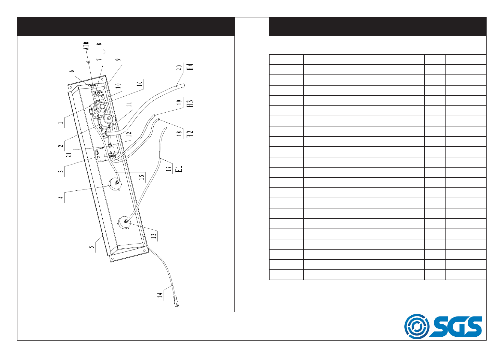
PARTS LIST EXPLODED VIEW OF LEFT BAR
Item No. Description Qty. Code
9-1 Left bar 1 905939
9-2 Straight Coupling 2 905992
9-3 Ball Valve 1 905993
9-4 Washer 2 905994
9-5 Moisture Separator 1 905995
9-6 Right-angle Quick Coupling 1 905996
9-7 Air Hose 1 905997
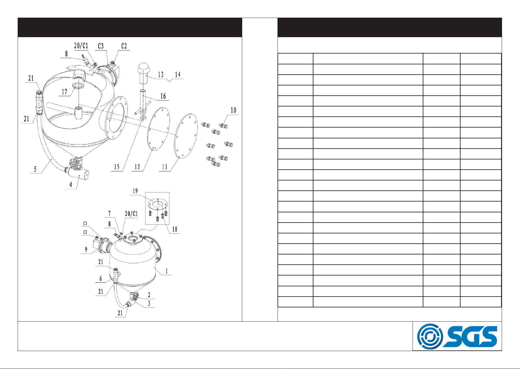
No Description Qty Code No Description Qty Code
1 Cabinet Assembly 1 905931 36 Air Spring Support Rod 2 905966
2 Grid 2 905932 37 Plastic Slot 1 905967
3 Bolt M6x16 (matched with φ6 x 16 washers) 22 905933 38 Switch Box 1 905968
4 PSA foam 1 905934 39 Front Door Latch 2 905969
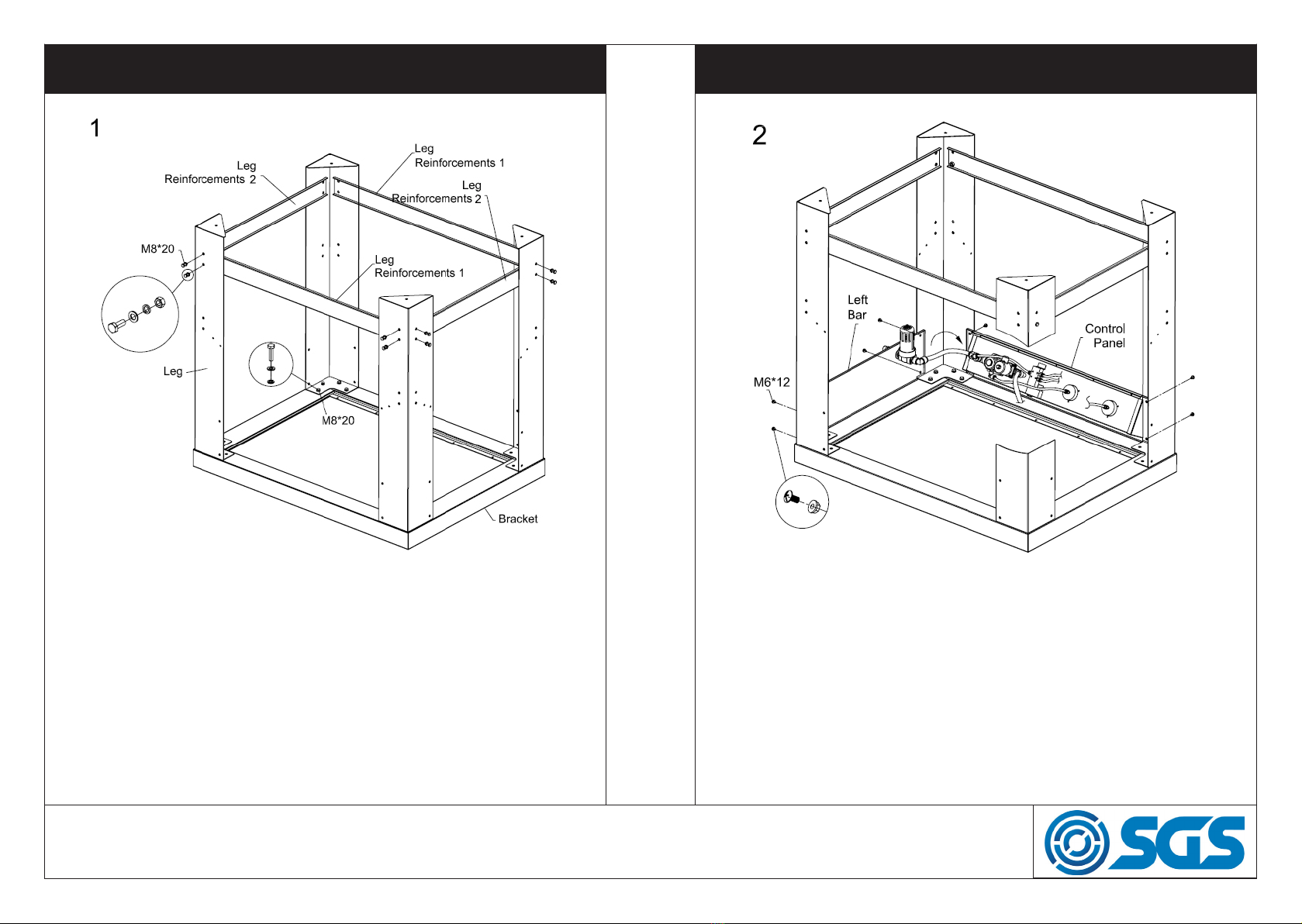
5 Bracket 1 905935 40 Latch Seat 2 905970
6 Cover grid 1 905936 41 Handle 2 905971
7 Funnel 1 905937 42 Glove Clamp 2 905972
8 Rear Bar 1 905938 43 Seal Ring of Glove 2 905973
9 Left Bar 1 905939 44 Front Door 1 905974
10 Bolt M6*12 24 905940 45 Front Bar 1 905975
11 Control Panel 1 905941 46 Glove 24” 1 905916
12 Tank Assembly 1 905942 47 Glove Seat 2 905977
13 Right Bar 1 905943 48 Nozzle Nut 1 905978
14 Bolt M8 x 20 32 905944 49 Nozzle 1 905979
15 Leg 4 905945 50 O-Ring 1 905980
16 Leg Reinforcements 2 905946 51 Nozzle Retainer 1 905981
17 Leg Reinforcements 2 905947 52 Abrasive Hose 1 905982
18 Stand 1 905948 53 Hook 1 905983
19 Foot Pedal 1 905949 54 Nozzle Seat 1 905984
20 Dust Collector 1 905950 55 Dust Baffle 1 905985
21 DC with power switch 1 905951 56 Pressure Hose Clamp 3 905986
22 Bolt M6 x 32 12 905952 57 Nozzle Retainer Adapter 1 905987
23 Window Frame 1 905953 58 4.2*12 screw 12 905988
24 Window Outer Lens 1 905954 59 Tee Joint Adapter 1 905989
25 Window Inner Lens 1 905955 60 Tee Joint Nut 1 905990
26 Window Underlay 1 905956 61 O-Ring 1 905991
27 PSA foam of Viewing Window 1 905957
28 Rubber Door Seal 1 905958
29 Lamp Housing 1 905959
30 LED Light 3 905960
31 Light Lens 1 905961
32 Light Lens Underlay 2 905962
33 Rubber Seal of Light Lens 1 905963
34 Cover Plate 2 905964
35 Main Support Pole 2 905965
WWW.SGS-ENGINEERING.COM
62Filter 1907032

PAGE 13
PAGE 12
EXPLODED VIEW OF CONTROL PANEL
Item No. Description Qty. Code
11-1 Pressure Regulating Valve 1 905998
11-2 Electromagnetic Valve 1 1 905999
11-3 Electromagnetic Valve 2 1 906000
11-4 Pressure Gauge 2 906001
11-5 Control Panel 1 906002
11-6 G1/2”-16 Straight Coupling 1 906003
11-7 Tee Joint 1 906004
11-8 G1/2”-G1/4” Bushing 1 906005
11-9 G1/4”- 8 Straight Coupling 2 906006
11-10 G1/2”Straight Coupling 2 906007
11-11 G1/2”-16 Straight Coupling 1 906008
11-12 G1/4”-8 Straight Coupling 3 906009
11-13 M10*11-8 Pressure Gauge Coupling 2 906010
11-14 Electromagnetic Valve Wire 1 906011
11-15 φ8 Air Pipe 1 906012
11-16 φ8 Air Pipe 1 906013
11-17/H1 φ8 Air Hose 1 906014
11-18/H2 φ8 Air Hose 1 906015
11-19/H3 φ8 Air Hose 1 906016
11-20/H4 φ16 Air Hose 1 906017
11-21 G1/8” Muffler 2 906018
PARTS LIST FOR EXPLODED VIEW OF CONTROL PANEL
WWW.SGS-ENGINEERING.COM

PAGE 15
PAGE 14
EXPLODED VIEW OF TANK ASSEMBLY PARTS LIST FOR EXPLODED VIEW OF TANK ASSEMBLY
Item No. Description Qty. Code
12-1 Tank 1 906019
12-2 Gate Valve 1 906020
12-3 G1/2” Straight Coupling 1 906021
12-4 Abrasive Tee Joint 1 906022
12-5 16mm Air Hose 1 906023
12-6 G1/2” Tee Joint 1 906024
12-7 G1/4” Y Joint 1 906025
12-8 Safety Valve 1 906026
12-9 Cylinder Block 1 906027
12-10 Bolt M8*30 8 906028
12-11 Service Port Cover 1 906029
12-12 Service Port Gasket 1 906030
12-13 Sealing Head 1 906031
12-14 Fixed-tube 1 906032
12-15 O-Ring 1 906033
12-16 Inlet Welding Assembly 1 906034
12-17 Closure Gasket 1 906035
12-18 Bolt M8*25 4 906036
12-19 Rubber Gasket 1 906037
12-20/C1 G1/4” Straight Coupling 1 906038
12-21 G1/2” 16 Straight Coupling 3 906039
12-C2 G1/8” Straight Coupling 1 906040
12-C3 G1/8” Straight Coupling 1 906041
WWW.SGS-ENGINEERING.COM

PAGE 17
PAGE 16
ASSEMBLY INSTRUCTIONS ASSEMBLY INSTRUCTIONS
Step 1. Connect and fasten
the four legs and the leg
reinforcements to the bracket
by using M8x20 mm bolts, flat
washers, lock washers and M8
nuts.
Hardware:
32 x M8x20 mm Bolt
16 x M8 Nut
48 x Flat washer 8
32 x Lock washer 8
Step 2. Assemble the left
bar, the right bar, the control
panel and the rear bar, for
each using a M6x12 mm bolt,
a flat washer and a M6 nut in
this sequence.
Hardware:
8 x M6x12 mm Bolt
8 x M6 Nut
WWW.SGS-ENGINEERING.COM

PAGE 19
PAGE 18
ASSEMBLY INSTRUCTIONS ASSEMBLY INSTRUCTIONS
#9 Cylinder block for tank
Step 3. Connect the discharge hose to the #9 Cylinder block
for tank.
Step 4. Place the funnel as
shown in the diagram. Attach
the tank assembly (including
bolt, flat washer, lock washer
and nut) and rubber seal onto
the funnel.
Hardware:
4 x M8x25 mm Bolt
4 x M8 Nut
4 x Flat washer 8
4 x Lock washer 8
1 x Rubber Gasket
WWW.SGS-ENGINEERING.COM

PAGE 21
PAGE 20
ASSEMBLY INSTRUCTIONS ASSEMBLY INSTRUCTIONS
Assemble #52 abrasive hose with tee joint
#9 Cylinder Block for tank
Step 5. Stand the lower assembly upright as shown, locate
#9 Cylinder Block for tank in the rear, and then assemble #52
abrasive hose with tee joint and install the discharge hose
thorugh the rubber retainer as shown.
Rubber seal
Step 6. Place #6 grid cover and insert the discharge hose
into the protective cover.
WWW.SGS-ENGINEERING.COM

PAGE 23
PAGE 22
ASSEMBLY INSTRUCTIONS ASSEMBLY INSTRUCTIONS
Electromagnetic valve 2 (#3)
Electromagnetic valve 1
#21 G1/2”-16 Straight
#9 Cylinder Block for
tank
Step 7.
a. There are two 8mm hoses (orange and blue). From Electro-
magnetic Valve 2 (#3) on control panel, connect with the two
adapters for #9 Cylinder Block for tank, as shown in the diagram
above: H2-C2 and H3-C3.
b. Connect the orange hose (16mm) from Electromagnetic valve
1(#2) on control panel straight to #21 G1/2”-16, as illustrated in
the diagram: H4-C4. Note: to release the hose, push the
plastic ring inward.
PSA Foam
Step 8. Assemble the right bar,
the rear bar and legs using the
M6x12 mm bolts and M6 nuts,
followed by installing the PSA
foam to the funnel as shown.
Hardware:
8 x M6x12 mm Bolt
8 x M6 Nut
PSA Foam Roll
WWW.SGS-ENGINEERING.COM

PAGE 25
PAGE 24
ASSEMBLY INSTRUCTIONS ASSEMBLY INSTRUCTIONS
Step 9. Place the grid on the
funnel and, with assistance,
place cabinet assembly on
the lower assembly, while
lining up the holes. Open the
door, assemble the cabinet
and funnel with the M6x16
mm bolts and 6 flat washers
Hardware:
22 x M6x16 mm Bolt
22 x 6 Flat washer
#4 Abrasive tee joint
Step 10.
a. Open the door, insert abrasive hose through rubber
retainer and adjust it, while avoiding sharp bends to help
prevent excessive wearing of the abrasive hose. Next, se-
cure the abrasive hose with a clamp and install the M6x12
mm bolts and M6 nuts.
b. Connect the abrasive hose to #4 abrasive tee joint and
seal thread with Teflon tape.
WWW.SGS-ENGINEERING.COM

PAGE 27
PAGE 26
ASSEMBLY INSTRUCTIONS
Step 11. Install nozzle retainer to end of the abrasive hose,
fasten the abrasive hose with 4.2x10 mm tapping screws.
Step 12. Attach the two dust
collectors (#20) on both sides
of the cabinet assembly #1
with M6x12 mm bolts (8PCS).
Hardware:
8 x M6x12 mm Bolt
ASSEMBLY INSTRUCTIONS
WWW.SGS-ENGINEERING.COM

PAGE 29
PAGE 28
ASSEMBLY INSTRUCTIONS ASSEMBLY INSTRUCTIONS
Stand and Cabinet Base
Step 13-1: Assemble the stand
using the M8x45 mm bolt, M8
Nut, 8 flat washer and 8 lock
washer.
Hardware used:
12 x M8x45 mm Bolt
12 x M8 Nut
24 x Flat Washer
12 x Lock Washer
Step 13-2: Install stand to
front legs of cabinet as shown
in the diagram using the
M8x45 mm bolts, M8 nuts, 8
flat washers and 8 lock
washers.
Hardware used:
4 x M8x45 mm Bolt
4 x M8 Nut
8 x Flat Washer
4 x Lock Washer
WWW.SGS-ENGINEERING.COM

PAGE 31
PAGE 30
ASSEMBLY INSTRUCTIONS SEALING HEAD REPLACEMENT GRAPHICS
Step 14: Plug the electromagnetic valve plug and foot pedal
plug into the power supply.
WWW.SGS-ENGINEERING.COM

PAGE 33
PAGE 32
WIRING DIAGRAM DC WITH POWER SWITCH WIRING DIAGRAM
WWW.SGS-ENGINEERING.COM

ASSEMBLED DIMENSIONS
EC Declaration of Conformity
This is an important document and should be retained
MANUFACTURER’S NAME:
TYPE OF EQUIPMENT:
PART NUMBER:
I, the undersigned, hereby declare that the equipment specied above
conforms to the above European Communities Directive(s) and
Standard(s).
PLACE:
DATE: (Signature)
Robert Wyatt
Company Secretary
Derby, UK
30th DEC 2019
SGS Engineering (UK) Ltd
West Side Park
Raynesway
Derby, DE21 7AZ
SHOT BLASTER CABINET
SSB500
2014/35/EU Low Voltage Directive
2014/30/EU EMC Directive
2012/19/EU WEEE Directive
2011/65/EU RoHS Directive
APPLICATION OF EC COUNCIL DIRECTIVES / STANDARD:
FOR YOUR SAFETY
PLEASE READ THESE INSTRUCTIONS CAREFULLY
AND RETAIN THEM FOR FUTURE USE.
Table of contents
Other SGS Shot Blasting Machine manuals