SGS SSB200 User manual

FOR YOUR SAFETY
PLEASE READ THESE INSTRUCTIONS CAREFULLY
AND RETAIN THEM FOR FUTURE USE.
OWNER’S MANUAL
SSB200
SHOT BLAST CABINET

PAGE 3
PAGE 2
SPECIFICATION
WARNING
Read and understand instructions before use.
Always wear eye/face and hand protection.
Do not use any silica based abrasives with this cabinet.
Silica based abrasives have been linked to severe res-
piratory disease. Always use recommended abrasives.
Abrasives used in this unit may be covered by COSHH.
INVENTORY
A - Cabinet B - Funnel C - Shelf D - Grid Support E - Legs
F - Gun & Hose G - Protective Film H - Transformer I - Pick-up Tube
J - Intake Vent Cover K - PTFE Tape L - Foam Strip (may be fitted)
M - Ceramic Nozzles (one nozzle fitted) N - Nuts, screws & washers
TOOL MODEL SSB200
TYPE FLOOR STANDING
VOLTS 12V
MIN AIR REQUIREMENT 10 CFM
MIN AIR REQUIREMENT 80-100 PSI
WWW.SGS-ENGINEERING.COM

PAGE 5
PAGE 4
ASSEMBLY
1. Lay the cabinet on its back and attach the four legs using the M6
x12mm screws, flat washers and nuts, ensuring the flat washers are
against the screw heads.
2. Fit the intake vent cover to the cabinet.
3. Attach the pick-up tube to the funnel as shown, using the M6 x 12mm
screws provided.
4. If not already fitted, peel the backing paper from the foam strip and
apply the strip to the edge of the grid support. Trim the strip accord-
ingly.
5. Use a punch (or similar) to make holes in the foam strip, at the bolt
holes.
6. Place the grid support on the funnel flange and the grid into the
recess in the grid support, so that the pick-up tube protrudes through
the grid neatly. Do not use undue force.
7. Turn the cabinet on to its legs then and with assistance, raise the fun-
nel to meet the underside of the cabinet, ensuring the pickup tube
is at the front of the cabinet. Bolt the funnel assembly to the cabinet
using the M6 x 20mm screws with the nuts and flat washers provided,
ensuring the flat washers are against the screw heads.
8. Open the cabinet door and attach the air hose from the gun to the
inlet port on the front of the cabinet, then connect the pick-up hose
from the gun to the pick-up tube attached to the funnel, securing with
the worm drive clip provided.
9. Attach the shelf to the legs using the screws and nuts provided.
ASSEMBLY
WWW.SGS-ENGINEERING.COM

PAGE 7
PAGE 6
OPERATION
Plug the transformer into the
power supply and switch the
power ON.
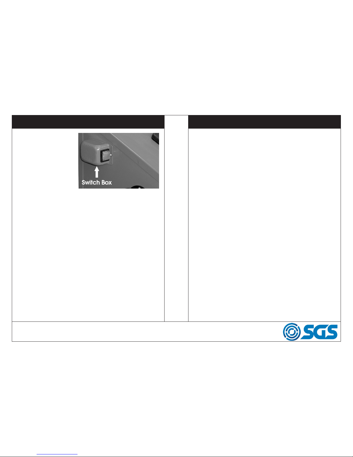
Switch the lamp ON by push-
ing the rocker switch on the
switch box ‘I’.
Switch OFF by pushing ‘O’.
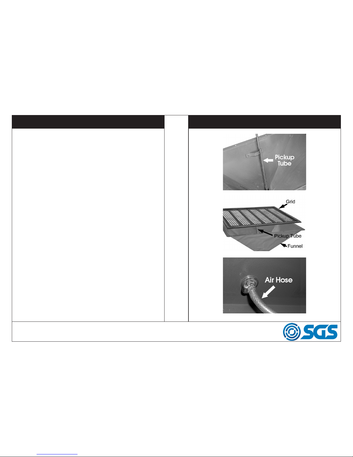
Ensure all air connections are
secure, and the pick up is
correctly located
beneath the grid, before filling the cabinet with abrasive media. Do not
fill higher than the level of the grid.
NOTE: PTFE tape is provided which may be used on the threads of the
various connectors to ensure an airtight connection.
Select the ceramic abrasive nozzle to produce the jet required for the
abrasive media being used, and assemble according to the instructions
given below.
Place the object to be cleaned in the cabinet, and close the lid, securing
with the swivel clip.
Turn on the extraction device which must be attached to the port on the
left side of the cabinet before turning on the air supply.
Set the pressure to the required value, but not higher than 100lbf/in2, and
check to ensure there are no air leaks. Should there be any, turn off the air
supply and repair where necessary, before turning the supply back on. Pull
the trigger on the gun and proceed to blast the object to be cleaned.
Keep the jet facing the object and away from the clear plastic lid. Do not
allow the jet to train on the rubber gloves, the air hose within the cabinet
or the fluorescent lamp.
OPERATION
When completed, release the trigger then turn off the air supply. As a
precautionary measure, ALWAYS pull the trigger before opening the lid.
NOTE: There are no hard or fast rules governing nozzle sizes and air
pressures used with different abrasives. With experience and
experimentation you will quickly learn the best combinations for
the required result.
NOTE: On more delicate parts, start with minimal air pressure to avoid
unnecessary peaning or excessive abrasion, and work up to a
setting to produce the desired finish.
WWW.SGS-ENGINEERING.COM

PAGE 9
PAGE 8
REPLACING THE ABRASIVE NOZZLE
Ensure the air supply is disconnected before performing this operation.
1. Pull the trigger of the gun as a precautionary measure.
2. Unscrew the end cap and withdraw the ceramic nozzle.
3. Replace with the nozzle of your choice and carefully thread the end
cap back on to the gun, taking great care NOT to cross thread the fine
thread.
NOTE: Should it be necessary to change the air nozzle, first remove the
abrasive nozzle as described above. A box spanner will be
required to unscrew and withdraw the air nozzle.
MAINTENANCE
Before use, check to ensure that all parts are serviceable, including the air
inlet hose and rubber gloves.
Ensure the air vent foam filter is in place.
The swivel clamps, securing the lid, must be secure so as not to allow the
lid to open during operation. The build up of air pressure within the cabi-
net could force the lid open, allowing abrasive to escape. This is not only
wasteful, but could be a health hazard.
Ensure the filters are serviceable and seated correctly.
Ensure you comply with all precautions regarding the use of compressed
air, and air compressor operation.
WWW.SGS-ENGINEERING.COM

PAGE 11
PAGE 10
CHANGING THE FLUORESCENT TUBE
Ensure the transformer is disconnected from the power supply before
opening the door and cutting the two ties securing the lamp to its retain-
ing clips. Carefully pull the lamp from the retaining clips then hold the clear
plastic protective outer tube firmly and ease off the plastic end cover from
the nonwired end. (This may take a little persuasion and perseverance).
Once the end cover has been removed, hold the end cover at the opposite
end (the cable input end), and pull off the outer protective clear plastic
tube. The fluorescent tube is now fully revealed.
Pull off the end connector, which secures a wire to one of the pins, taking
care not to distort the aluminium reflector. Then pull off the wire secured
by a plastic sheath to one of the pins at the cable input end.
Assemble in reverse order, ensuring the wires are correctly held by the plas-
tic sheath at one end and the end connector at the other, with the reflector
correctly in position.
Re-fit the assembly into its retaining clips and test its operation by plugging
the transformer into the mains.
TROUBLESHOOTING
Excessive dust in the
cabinet.
No dust extract device
used.
Install dust extract
device.
Air vent or overflow
blocked.
Clean rear vent and
keep vent away from
any wall.
Abrasive media worn. Replace abrasive media
Too much abrasive me-
dia in the cabinet.
Remove excessive
media.
Loose airline or loose
connections.
Tighten fittings and
ensure airline is secure.
Uneven blasting
action
Too much abrasive me-
dia in the cabinet.
Remove excessive
media.
Abrasive is damp. Renew abrasive or dry
thoroughly before use.
Moisture present inside
cabinet.
Check airline to ensure it
is free from moisture.
Inadequate speed or
inefficient blast.
Abrasive media worn. Replace abrasive media
Pressure too low. Increase inlet pressure
and ensure control valve
is fully open.
Static electricity
present
Dry weather conditions. Leave the item to be
cleaned on the grid.
Excessive media
blown into the
surrounding
atmosphere when no
vacuum extract is
being used.
Lid not secure. Secure the lid with the
swivel clips and adjust
them if necessary.
Air vent filter missing. Replace filter or blank off
hole in rear panel
temporarily with masking
tape.
WWW.SGS-ENGINEERING.COM

PAGE 13
PAGE 12
PARTS LIST PARTS LIST
No Description Part No No Description Part No
1 Cabinet 903558 23 Air Adaptor Nut 903580
2 Intake Guard Ring 903559 24 Low Voltage Light 903576
3 Intake Vent Cover 903560 25 Light Clamp 903581
4 Hinge 903561 26 Steel Screen 903582
5 Plastic Door 903562 27 Cotton Sealant 903583
6 Metal Liner 903563 28 Cabinet Duct 903584
7 Gloves (pair) 903564 29 Abrasive Suction Pipe 903585
8 Clamp for Glove 903565 30 Abrasive Removal Cover 903586
9 Glove mounting ring 903566 31 Cover Lock 903587
10 Rubber Insert 903567 32 Shelf 903588
11 Suction Flange 903568 33 Legs 903589
12 Suction Flange Cover 903569 34 Feet 903590
13 Switch 903570 35 Abrasive Intake Hose 903591
14 Low Voltage Switch Box 903571 36 Abrasive Gun 903592
15 Low Voltage Plug 903572 37 Nozzle Adapter Nut 903593
16 Adaptor 903573 38 Nozzle 903594
17 Plastic Frame 903574 39 Clamp 903595
18 Plexiglass 903575 40 Air Hose Adaptor 903596
19 Glass 903576 41 Clamp 903597
20 Protective Film 903577 42 Air Hose 903598
21 Cotton Sealant 903578 43 Flat Washer 903599
22 Swivel Clip 903579
WWW.SGS-ENGINEERING.COM

EC Declaration of Conformity
This is an important document and should be retained
MANUFACTURER’S NAME:
TYPE OF EQUIPMENT:
PART NUMBER:
I, the undersigned, hereby declare that the equipment specied above
conforms to the above European Communities Directive(s) and
Standard(s).
PLACE:
DATE: (Signature)
Robert Wyatt
Company Secretary
Derby, UK
24th MAY 2018
SGS Engineering (UK) Ltd
West Side Park
Raynesway
Derby, DE21 7AZ
Shot Blast Cabinet
SSB200
2004/108/EC Electromagnetic Compatibility Directive
2006/95/EC Low Voltage Equipment Directive
2002/95/EC Restriction of Hazardous Substances
APPLICATION OF EC COUNCIL DIRECTIVES / STANDARD:
Table of contents
Other SGS Shot Blasting Machine manuals