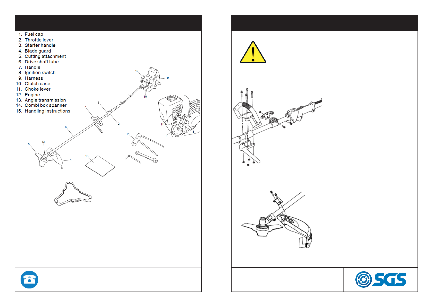
PAGE 5
PAGE 4
FOR SAFE OPERATION
Do not wear loose clothing, jewelry, short trousers,
sandals, or go barefoot. Do not wear anything
which might be caught by a moving part of the unit.
Secure hair so it is above shoulder length.
Never use the product when the ground is slippery,
in the nightime or in the bad weather conditions.
Never use this product when tired, under the
influence of alcohol, or if you are taking medication
that could affect your vision, your judgment or your
coordination.
Check the condition of working area to avoid any
accident by hitting hidden obstacles such as stumps,
stones, cans, or broken glass.
Remove any obstacle before beginning work. Inspect
the entire unit for loose fasteners and fuel leakage.
Make sure that the cutting attachment is properly
installed and securely fastened. Be sure the cutting
attachment guard is firmly attached in place. Always
use the harness. Adjust the strap for comfort before
starting the engine. The strap should be adjusted so
the left hand can comfortably hold the handlebar
grip approximately waist high.
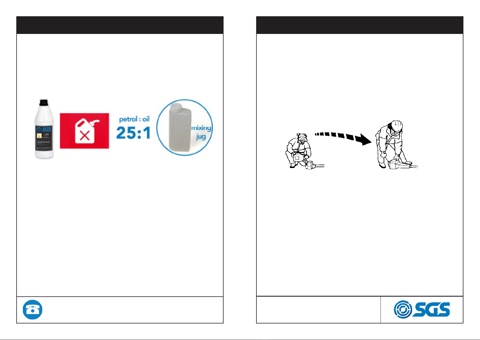
When starting the engine, place the product onto
the ground in a flat clear area and hold it firmly in
place so as to ensure that neither the cutting contact
with any obstacle when the engine starts.
FOR SAFE OPERATION
After starting the engine, check to make sure that the
cutting attachment stops rotating when the throttle is
moved fully back to its original position.
Cut only materials recommended by the manufacturer.
Use only for tasks explained in the manual.
Maintain the speed of the engine at the level required
to perform cutting work, and never raise thespeed of the
engine above the level necessary.
If the unit starts to shake or vibrate, turn off the engine
and check the whole unit. Do not use it until the trouble
has been properly corrected.
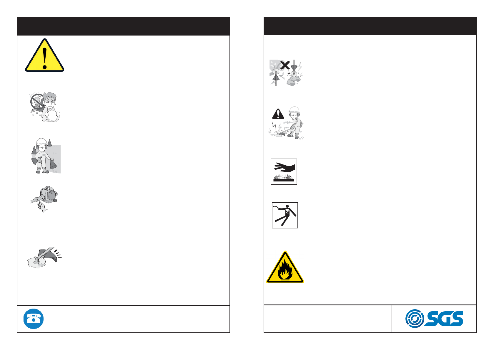
Never touch the muffler, spark plug, or other metallic
parts of the engine while the engine is in operation or
immediately after shutting down the engine. Doing so
could result in serious burns or electrical shock.
Approaching or contacting electric power lines with
pruning saw may cause serious injury or death from
electrocution.
Always be sure to turn off the engine and disconnect the
spark plug wire before performing any maintenance or
checking procedures.
The engine of the product we offer is designed to run
on a mixed fuel, which contains highly flammable
gasoline.
WWW.SGS-ENGINEERING.COM
CALL FOR ASSISTANCE: 01332 576 850