Shad Y0XJ69SF User manual

B
3
8
2
7
B
D
F
E
2
1
A
C
YAMAHA XJ 600 ‘09
KIT SIDEMASTER
Y0XJ69SF
1.
2.
Consejo para un correcto montaje del kit:
No apretar los tornillos del todo hasta asegurarse que el KIT esta correctamente colocacado y
alineado. En caso de montar los soportes KIT (Y0XJ69SF) y su moto ya posee los soportes KIT TOP (Y0XJ69ST), éstos se deberán desmontar para
montar el soporte KIT SIDE y encima de éste el soporte KIT TOP.
Advice for correct fitting of the kit: Ensure that the kit is correctly fitted and aligned before sidey tightening the screws. In case you
want to assemble the KIT supports (Y0XJ69SF) and your motorcycle already has the KIT TOP supports (Y0XJ69ST), you must first
disassemble the latter in order to assemble the KIT SIDE support and then reassemble the KIT TOP support over it.
Conseil pour un montage correct du kit: Ne pas serrer complètement les vis avant d’être sûr que le kit soit correctement monté et
ajusté. Pour monter les supports KIT (Y0XJ69SF), si la moto a déjà les supports KIT TOP (Y0XJ69ST), vous devez les démonter
d’abord pour monter le support KIT SIDE et au-dessus de ce dernier y placer le support KIT TOP.
Hinweis für einen korrekten Einbau des Bausatzes: Die Schrauben nicht ganz anziehen, bis der Kit korrekt placiert und ausgerichtet ist. Falls die
Baukastenständer (Y0XJ69SF) aufgebaut werden und das Motorrad schon mit einer KIT TOP-Ständervorrichtung (Y0XJ69ST) ausgerüstet ist, muss
dieser abgebaut werden um die Ständervorrichtung KIT SIDE zu montieren und auf diese wiederum die Ständervorrichtung KIT TOP zu montieren.
Consiglio per un montaggio corretto del kit: Non stringere del tutto le viti fino a che non vi siate assicurati che il kit sia correttamente
collocato e allineato. Nota: In caso di montare i supporti KIT SIDE (Y0XJ69SF) e la sua moto ha già i supporti KIT TOP (Y0XJ69ST), dovrà
smontare questi, montare in primo luogo il KIT SIDE ed in seguito montare i supporti KIT TOP.
Abrir el asiento (A) y desmontar el agarradero
posterior (B) mediante los tornillos (C) que se
desestiman. Desmontar y desestimar los intermitentes
(D). En zona estribera (E), cambiar los pasadores (F)
por los tornillos (1) y arandelas (2).
Open the seat (A) and disassemble the rear handle (B)
by means of the screws (C) that must be discarded.
Disassemble and discard the indicators (D). In the
stirrup zone (E), change the pins (F) for the screws (1)
and washers (2).
Ouvrir le siège (A) et démonter la poignée arrière (B)
au moyen des vis (C) les rejetant. Démonter et jeter
les feux clignotants (D). Dans la zone des repose-
pieds (E), changer les agrafes (F) par des vis (1) et
rondelles (2).
Öffnen Sie den Sitz (A) und lösen Sie den hinteren
Griff (B) durch die Schrauben (C). Lösen Sie die
Blinker (D) und beseitigen Sie sie. Tauschen Sie die
Stifte (F) im Bereich der Fußrasten (E) mit den
Schrauben (1) und den Metallringen (2) aus.
Aprire il sedile (A) e smontare la maniglia posteriore
(B) mediante le viti (C) che devono essere scartati.
Smontare e scartare i lampeggiatori (D). Nella zona
della staffa (E), sostituire il clip di fissaggio (F) con le
viti (1) e le rondelle (2).
En zona delantera agarraderos posicionar los
distanciadores (7) y en la trasera el soporte SIDE (3),
colocaremos encima el agarradero posterior (B) y lo
fijaremos todo mediante los tornillos (8) y las
arandelas (2).
In the front zone, place the handles by means of the
spacers (7), and in the rear zone, place the SIDE
support (3). Place the rear handle (B) on top and
fasten it by means of the screws (8) and the washers
(2).
Dans la zone poignée avant, placer les entretoises (7),
et dans la zone arrière, le support SIDE (3); y placer
au-dessus la poignée arrière (B) en fixant tout
l’ensemble au moyen des vis (8) et des rondelles (2).
Positionieren Sie die Abstandshalter (7) im vorderen
Bereich des Griffs und im hinteren Bereich die
Stützvorrichtung SIDE (3), worauf Sie dann den
hinteren Griff (B) einstellen und durch die Schrauben
(8) und Metallringe (2) befestigen.
Nella zona anteriore, posizionare i separatori (7), e
nella zona posteriore i supporti SIDE (3). Collocare la
maniglia posteriore (B) sopra e fissare mediante le viti
(8) e le rondelle (2).

A
3
22
E
E
56
4
1
Montar los soportes KIT SIDE (3) en zona estribera (E) mediante los tornillos
(1), arandelas (2), los distanciadores (4) y las tuercas (5), y por último lo
más importante, por sistema de seguridad colocar el clip pasador (6) y
realizarles los pliegues para asegurar su correcto montaje según nos muestra
el dibujo. Nota: No circular con la moto provista del KIT SIDE, sin
asegurarse de que el clip pasador (6) está colocado.
Assemble the KIT SIDE supports (3) in the stirrup zone (E) by means of the
screws (1), washers (2), spacers (4) and nuts (5). Last and most importantly,
for security reasons place the clip pin (6) and fold it to ensure the correct
assembly as shown in the picture. Note: Make sure the clip pin (6) is properly
placed before circulating with your motorcycle equipped with the KIT SIDE.
Monter les supports KIT SIDE (3) dans la zone repose-pieds (E) au moyen
des vis (1), des rondelles (2), des entretoises (4) et des écrous (5); et,
finalement, le plus important: comme mesure de sécurité, placer les clips-
agrafe (6) en les pliant comme montre le design, pour un correcte montage.
Attention: Ne mettre pas en circulation la moto avec le KIT SIDE avant
d’être sure que le clip-agrafe (6) soit correctement placé.
Montieren Sie die Stützvorrichtungen KIT SIDE (3) im Bereich der Fußrasten
(E) mithilfe der Schrauben (1), der Metallringe (2), der Abstandshalter (4)
und der Schraubenmuttern (5) und das Wichtigste, stellen Sie die Klammer
(6) ein und führen Sie die Falzung durch um sich eines korrekten Einbaus
laut des Musters zu vergewissern. Hinweis: Benutzen Sie das Motorrad mit
dem KIT SIDE nicht, bevor Sie sich nicht vergewissert haben, dass die
Klammer (6) eingestellt ist.
Montare i supporti KIT SIDE (3) nella zona della staffa (E), mediante le viti
(1), le rondelle (2), i separatori (4) ed i dadi (5); ed infine la cosa più
importante: per sicurezza, collocare la clip di fissaggio (6) e fare le
plissettature per assicurare il montaggio corretto secondo il disegno. Nota:
Non circolare con la moto provvista di KIT SIDE senza aver controllato che la
clip di fissaggio (6) sia stata collocata.
COMPONENTES /
PARTS
/ COMPOSANTES /
EINZELBAUTEILE
/ COMPONENTI:
YAMAHA XJ 600 ‘09
KIT SIDEMASTER
Y0XJ69SF
REF. 500479
Edición 1ª
3.
4.
Pos. Ref. Cant.
1 304172 2 Tornillo M8 x 70 DIN 7380 Ø2 -
Screw -
Vis -
Schraube -
Vite
2 303020 8 Arandela Ø8 -
Washer
- Rondelle -
Scheibe
- Rondella
3 261121 1 Soporte derecho side -
Side right support
- Support droit side -
Rechter Side-Träger
- Supporto destro side
261202 1 Soporte izquierdo side -
Side left support
- Support gauche side -
Linker Side-Träger
- Supporto sinistro side
4 260417 2 Distanciador Ø16 Ø9 x 16 -
Spacer
- Entre-toise -
Abstandshalter
- Distanziatore
5 302024 2
Tuerca M8 autoblocante - Self-blocking Nut M8 - Écrou M8 autobloquant - Selbstanziehende Mutter M8 - Bullone M8 autobloccante
6 305053 2 Clip pasador -
Retaining clip
- Goupille clip -
Rechter Full-Träger
- Fermaglio di sicurezza
7 260648 2 Distanciador Ø16 Ø9 x 5 -
Spacer
- Entre-toise -
Abstandshalter
- Distanziatore
8 304053 4 Tornillo M6 x 30 DIN 7380 -
Screw -
Vis -
Schraube -
Vite
9 261203 1 Soporte tubo unión -
Junction tube support
- Support d’attache du pot -
Linker Full-Träger
- Supporto tubo d'unione
10 304052 2 Tornillo M6 x 20 DIN 7380 -
Screw -
Vis -
Schraube -
Vite
11 303000 4 Arandela Ø6 -
Washer
- Rondelle -
Scheibe
- Rondella
12 302021 2
Tuerca M6 autoblocante - Self-blocking Nut M6 - Écrou M6 autobloquant - Selbstanziehende Mutter M6 - Bullone M6 autobloccante
13 260695 4 Brida de PVC negra -
Black PVC bridle
- Attache en PVC noire -
Flansch aus schwarzem PVC
- Morsetto di PVC nero
Uniremos los soportes KIT SIDE (3) mediante el soporte unión varilla (9), los
tornillos (10), las arandelas (11) y las tuercas (12). Realizar la conexión de
los intermitentes incluidos en este KIT, fijar los cables con las bridas (13).
Montar el asiento (A).
Join the KIT SIDE supports (3) by means of the rod joint support (9), the screws
(10), the washers (11) and the nuts (12). Connect the indicators included in
this kit and secure the cables with the bridles (13). Assemble the seat (A).
Joindre les supports KIT SIDE (3) au moyen du support tige jonction (9), des
vis (10), des rondelles (11) et des écrous (12). Réaliser la connexion des
feux clignotants y compris dans ce KIT, fixant les câbles avec les brides
(13). Monter le siège (A).
Verbinden Sie nun die Stützvorrichtungen KIT SIDE (3) mithilfe der
Stützvorrichtungsstäbchen (9), Schrauben (10), Metallringe (11) und
Schraubenmuttern (12). Ermöglichen Sie die Verbindung der
miteingeschlossenen Blinker in diesem Baukasten indem Sie die Kabel mit
den Flanschen (13) befestigen. Montieren Sie den Sitz (A).
Unire i supporti KIT SIDE (3) mediante la biella unione (9), le viti (10), le
rondelle (11) ed i dadi (12). Effettuare il collegamento dei lampeggiatori forniti
in questo KIT SIDE, fissarli mediante bocchettoni (13). Montare il sedile (A).
9
12
11
11
10
Table of contents
Other Shad Bicycle Accessories manuals
Popular Bicycle Accessories manuals by other brands
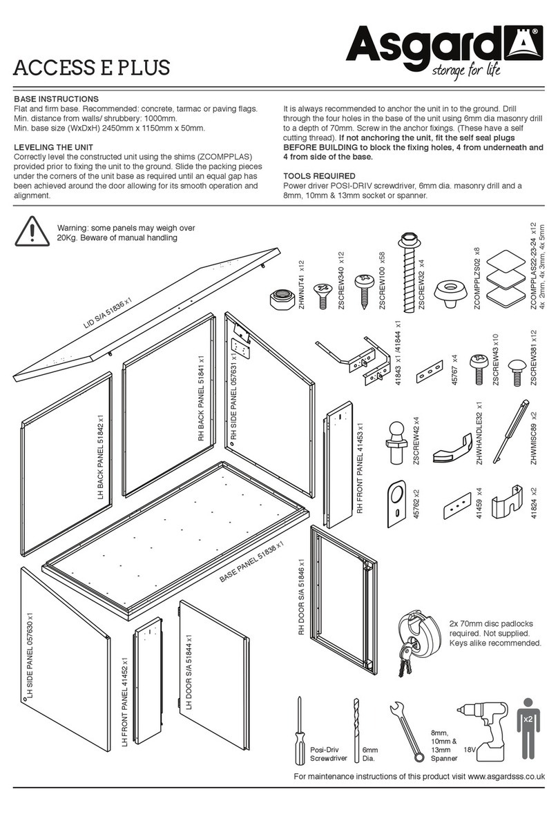
Asgard
Asgard ACCESS E PLUS manual

VDO Cyclecomputing
VDO Cyclecomputing M6.1 Short instruction manual
CAMPAGNOLO
CAMPAGNOLO 11 Speed manual
Fidlock
Fidlock TWIST quick start guide

VDO Cyclecomputing
VDO Cyclecomputing Z3 PC-LINK Instruction manuals

Rose electronics
Rose electronics LOWRIDER LR-1 owner's manual
