ShadeTree The Bungalow User manual
Dear Customer:
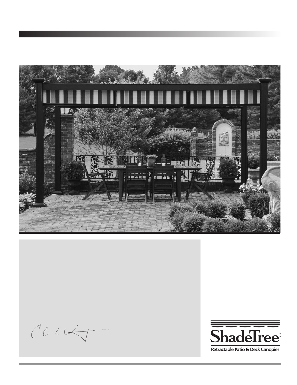
Thank you for purchasing our ShadeTree®Canopy System. We trust these assembly
instructions will be satisfactory for your installation. If you have any questions, please feel
free to call 1-800-894-3801.
And here’s a special offer we’d like to make to you: Send us a photo of your new
ShadeTree®installation and we will send you $50 if we use your photo in our advertising
materials. Before and after pictures will receive an additional $50. A deck or patio that is
nicely furnished helps us communicate to prospective customers how nice a ShadeTree®
patio can be.
We hope you enjoy your new ShadeTree®patio canopies.
Sincerely,
Colin LeVeque, President
ShadeTree Systems, LLC.
2012
The Bungalow
Using ShadeTree®Aluminum Overhead Tracks supported
by a Bungalow aluminum support structure
ShadeTree®Canopy Systems Assembly Instructions
ShadeTree Cool Living, LLC |6317 Busch Blvd. |Columbus, Ohio 43229 |800-894-3801 |fax 614-844-5991 |www.shadetreecanopies.com
Complete Aluminum System
(supported by an aluminum frame)
ShadeTree Cool Living, LLC — For questions or assistance call 800-894-3801 .
2
The Bungalow
ShadeTree®Canopy Systems Assembly Instructions
TRIM PANEL
TRIM PANEL
OTE: You’ll find a second pair of hands (to hold parts as the
unit goes up) to be very helpful in erecting your system.
Other Materials Required:
You will also need 4” x 4” wooden posts for added strength
inside aluminum columns. Pre-selection of pressure-treated
wood is very important. Any warped or oversized lumber will
not fit inside the aluminum columns. If sinking posts into the
ground, treated lumber is required.
If mounting on a deck, patio, the surface must be connected to
solid anchor points. If not, the posts must be sunk inot the
ground. If you wish to cement the posts 3’ into the ground, 12’
posts are needed. The aluminum framework should be
completely assembled before cement is poured into the holes.
If you are sinking posts into the ground, the Column Bases are
optional. If you prefer to use the Column Bases, they should be
assembled onto the wood posts before erecting the system.
ShadeTree®Canopy Systems Assembly Instructions
The Bungalow
ShadeTree Cool Living, LLC — For questions or assistance call 800-894-3801 .3
CAD –YOUR PROVIDED CUSTOM BLUEPRI T :
Each ShadeTree Pergola will ships with a custom-designed
CAD drawing showing all of the dimensions neccessary for
installation. Please refer to this CAD for all steps in these
instructions. If a CAD did not come with your ShadeTree
system, please call customer service before proceeding with
installation.
Large Roof
Bracket
Optional installation accessories:
Column
Anchor
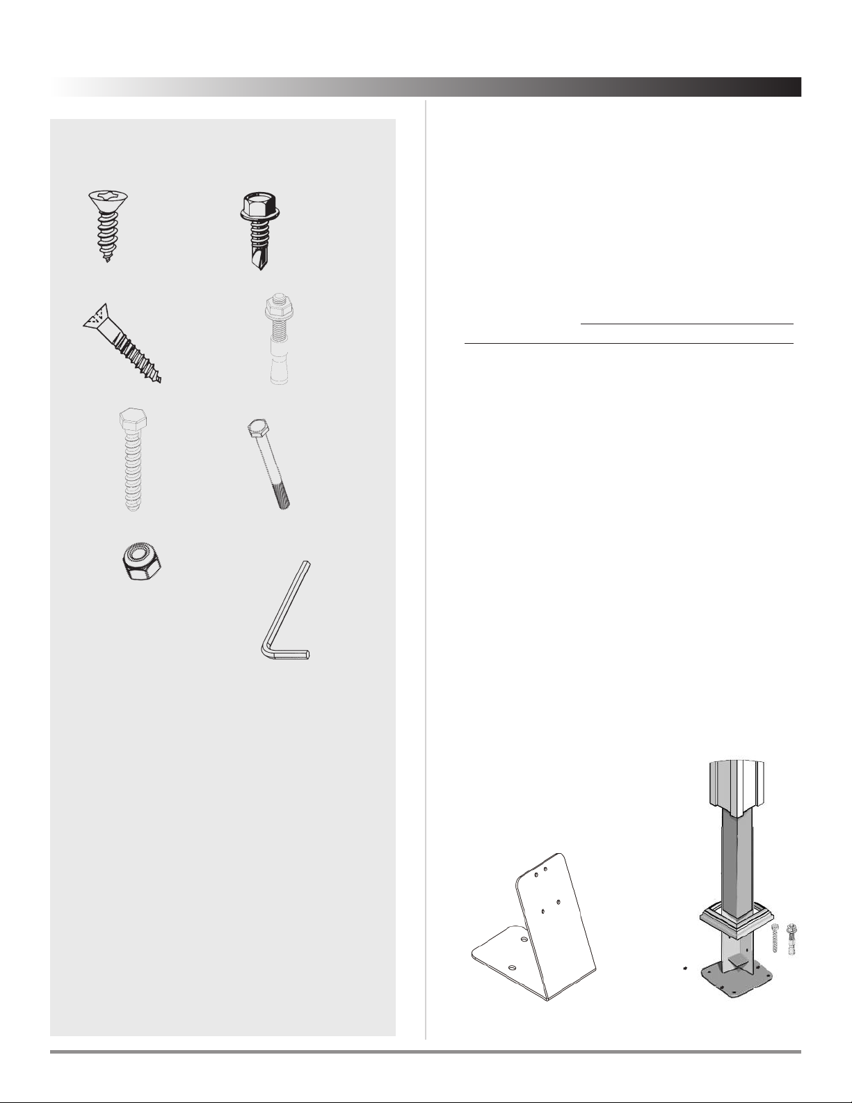
Fasteners & hardware provided:
#F010 End and
Base Screw #F011
1” Self-drilling
#10 ex Screw
#F052
3/8” Wedge
Anchor
#F001 Nut Allen Wrench
#F053
Lag Bolt for
Anchor
#F002 2-3/4”
Long Bolt
A. B.
G.
.
D.
E. F.
#F061
3” Wood
Screw
C.
Tools required:
1. Phillips screwdriver
2. and drill
3. 9/64”, 1/4” & 3/4”
drill bits
4. pencil
5. bubble-type level
6. Carpenter’s square
7. tape measure
8. hand saw
9. 8’ ladder
If driving screws with a drill or power screwdriver, set the
torque to a low setting to avoid stripping screw heads.
Mark the center location for each
End Mounting Bracket
on the
house 5-4” or 4’-2” apart (refer to the supplied CAD of your
system). One
End Mounting Bracket
is needed for every
projection beam. Be sure to allow approximately 4” on the
outside of outermost brackets for inserting bolts into brackets.
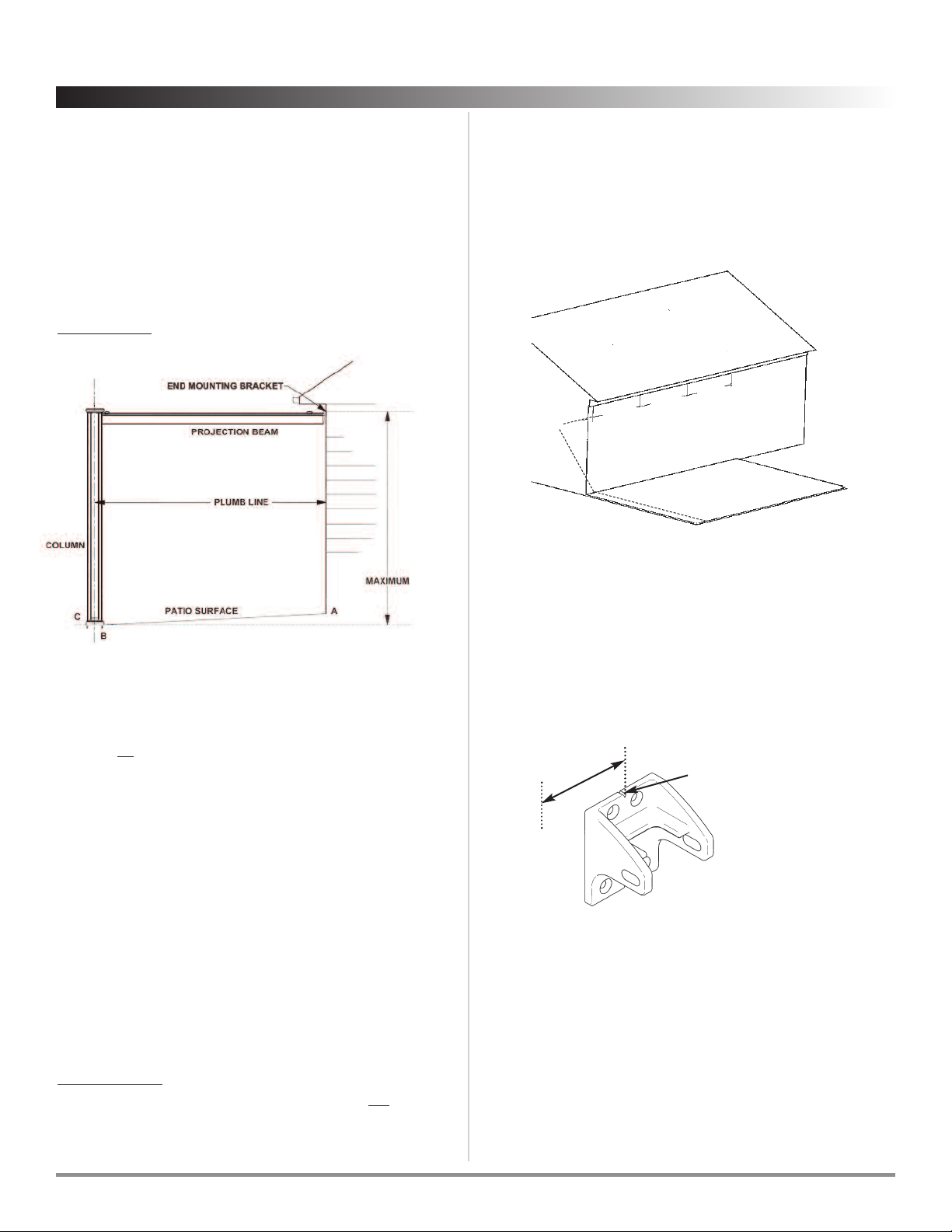
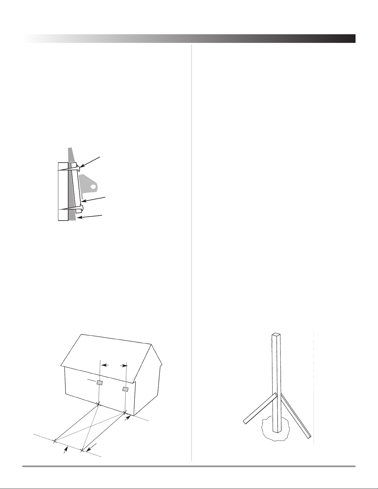
Step 2 Attach End Mounting Brackets
Mount the
End Mounting Brackets
on each center mark, using
the center notch as a guide. The brackets should be mounted
so that the the slanting edge of the bracket is to the top (as in
illustration). Be sure to mount the brackets level with each
other. Use a 9/64” drill bit to drill pilot holes. Wood screws are
included (1-1/4” screw c). . . any other type of screws (such as
masonry screws for brick or stone) can be purchased from
your hardware store. The Bracket can be used as its own
template for marking pilot holes.
5’4”
or
4’2-1⁄4”
5’4”
or
4’2-1⁄4”
5’4”
or
4’2-1⁄4”
4” min
When mounting to house, brackets must be attached to
well-secured wood, brick or stone.
• If mounting to a house with wood siding, or to wood trim,
use the 1-1/4” #10 wood screws with the painted heads.
• If mounting to a masonry wall (brick or stone) concrete
fastening screws must be used. Consult your hardware
store for the best fastener for your situation.
Center notch for 5’-4”
or 4’-2-1/4”alignment
Allow 2” beyond
center of bracket
2”
ShadeTree Cool Living, LLC — For questions or assistance call 800-894-3801 .
4
The Bungalow
ShadeTree®Canopy Systems Assembly Instructions
If there is no “fall” in your deck or patio surface (in most cases,
there is some fall so rain will drain away from the house), you
can place the End Mounting Bracket as high as 9’ 2-3/4” from the
patio surface at the house (A). owever, if there is fall from your
house (A) to the place where the columns are to be placed (C),
it is necessary to adjust the height of the End Mounting
Brackets to accommodate for this difference in surface levels.
See the CAD drawing that came with the system to determine
distance from house to center of Column (B). To determine the
“fall” from your house to the surface on which the columns will
be anchored (C), extend a string level from base of house (A) to
the to center line of Column (B) and measure the distance (fall)
from level line at (B) to mounting surface (C).
Subtract the “fall” dimension from 9 ’2-3/4” to determine the
maximum height (based on 10’ columns, if you are using 12’ or
higher columns, add 2’ respectively) at which the top of the
mounting bracket can be installed. Mark this position
temporally on the house.
See following illustration and dimensions to determine
maximum height of End Mounting Bracket on the house.
Step 1 Determine the height of your ShadeTree®
Bungalow System
To determine the height at which to place the End
Mounting Brackets (which hold the Pro ection Beams ) on the
house, it is important to know the maximum height of the
mounting bracket relative to the maximum height of the
aluminum columns.
For a standard 10’ column, the maximum height to top edge of End
Mounting Bracket is 9’ 2-3/4” from surface on which columns will be
anchored. (See vertical arrow at far right side of diagram above. )
FIGURE 1
Screw or nail into
studs to support
1” x 4” board
Aluminum or
vinyl siding
1” x 4” board
Stud
• If attaching to stucco, aluminum, or vinyl siding, the screws
must make contact with wood. On two story houses, this can
usually be done in the area of the second floor joists. When
no wood can be found to carry the canopy load, it is
recommended to attach a 1’’ x 4” board to the home (see
illustration below) . . . horizontally at the height desired for
the canopy. The board can then be secured by screws into
each stud. On aluminum or vinyl siding, tighten the bottom
screws only enough to hold board snugly. Over-tightening
can compress the siding. The board can be painted or
stained to match the siding.
Using the CAD for your system, measure out from the house to
the location of your first Aluminum Column(A). Measure out
from the house a second time to the location of your second
Aluminum Column(B). Be sure that points A & B are on a line (C)
that is parallel with the wall to which the End Mounting
Brackets are attached.
To ensure that your system will be square, measure the distance
from point B to point D. Then measure the distance from point
A to point C. Move points A and B right or left to get B to D and
A to C equal.
5’-4”
or 4’-21⁄4”
End
Mounting
Bracket
FIG 1
Line C
Step 3 Determine location of Aluminum Columns
B
C
D
A
Post location
measurement
ShadeTree®Canopy Systems Assembly Instructions
The Bungalow
ShadeTree Cool Living, LLC — For questions or assistance call 800-894-3801 .5
Step 4 – Preparing the surface
If you do not have a level surface (most patios have a slight
slope to shed water), you may need to cut the columns that
are to be placed on the high side of the mounting surface. You
should first establish the difference in elevation (you can use
a level and tape measure if necessary). Next measure up, from
the bottom of the column, the difference in elevation, and
place a mark on the column. (You should only cut the
column from the bottom). It is important that your
ShadeTree structure be built so the beams and headers are
level. A deck or patio is an ideal surface. Another option is to
set 4x4s into 3’ deep hole and encase in concrete.
Step 5 - Internal Post assembly
(set or surface-mounting)
Step 5 - Option A: Wood posts set in concrete:
Dig holes and secure posts
You will need 12’ or longer 4x4 posts when setting posts into
concrete. We recommend that you use pressure treated
lumber for this application. Once you have determined the
post locations, you can begin digging the holes. You should
dig the holes to a depth of 3 feet. Put posts in holes; check
that wood posts are plumb and square using a bubble level,
and extend above ground level at least 1’ higher than your
ultimate system height. Stabilize the posts temporarily by
attaching scrap lumber into the posts as illustrated in Figure
5A. Mix concrete according to manufacturer’s instructions
and pour into holes & resume assembly once cement is dry.
4x4 wood post
in concrete with
scrap lumber supports
FIG 5A
ShadeTree Cool Living, LLC — For questions or assistance call 800-894-3801 .
6
The Bungalow
ShadeTree®Canopy Systems Assembly Instructions
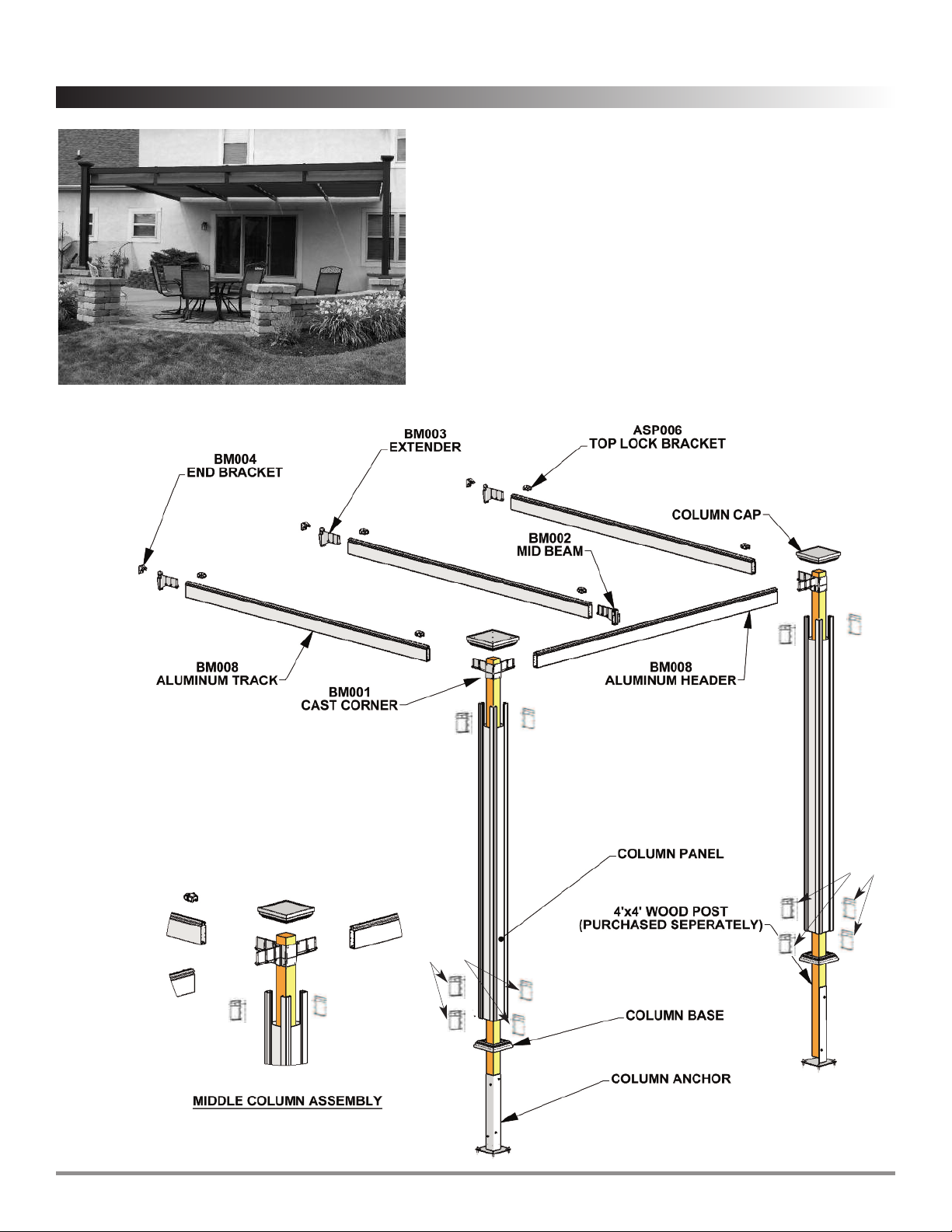
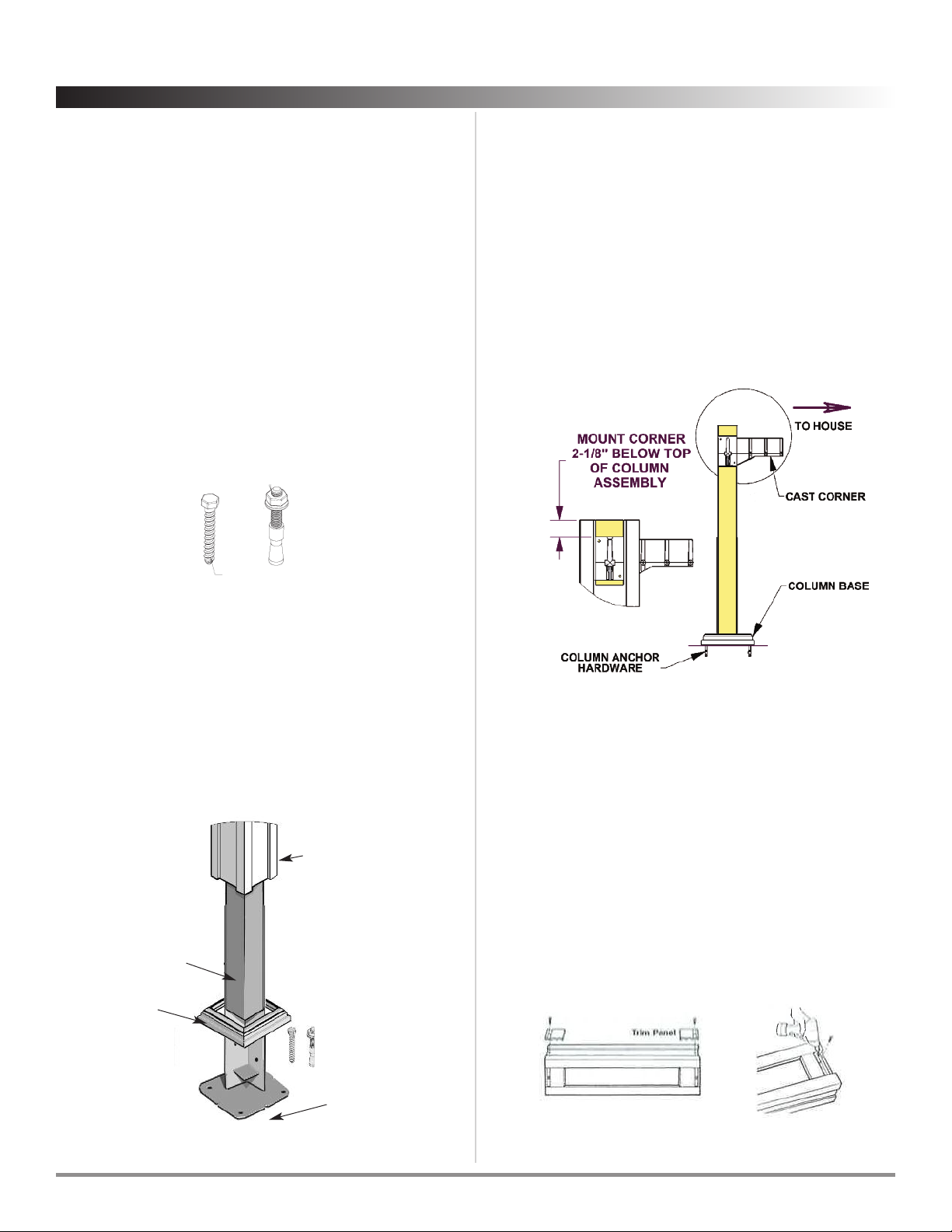
Step 6 Attach Corner Brackets
Slide the Cast Corner Bracket into th the top of the Column
Assembly. Position the Bracket so that it is 2 1/8” below the top
of the Column Assembly and then screw the Bracket into the
wood post. Ensure that the vertical Column Assembly is square
with the mounting surface and with the house. Place a bubble
level on top of the Header Beam to confirm that it is level. If it
is not, reposition the Corner Brackets and lower or raise the
Corner Brackets on the Wood Post as necessary. Once level,
fasten each corner with eight #10 x 3” wood screws F061.
Step 8 Attach Trim Panels
Locate the Top and Bottom Trim Panels in recessed area of
column quarter staves with grooves nearest ends of column
quarter staves. Position Trim Panels so grooved edge is flush
with outer end of quarter stave.
Using the hole in the trim panel groove as a template, drill a
1/8” hole through Column Assembly and attach Trim Panel to
the column with a 8” x 3 /4” large Phillips flat head stainless
sheet metal screw (furnished). Follow the same procedure on
all four staves. Each Column Assembly will have two Trim
Panels at the top and four at the bottom.
Attach wood post to Column Anchor
With Anchor in vertical position on the ground, attach each
wood 4x4x10’ post onto the Column Anchor. Install the 4
screws through the steel support into the 4x4 wood posts.
FIG 5B
Step 5 Option B – Surface-Mounting using Column
Anchors
BW006
COLUMN BASE
4X4 LUMBER
(CUSTOMER SUPPLIED)
BW013 (4 PANELS)
COLUMN ASSEMBLY
AS022
POST ANC OR
If attaching to a wood surface Use the Column Anchor as a
template and pre-drill - using the inner holes, not the outer -for
the 3/8” x 2 1/2” lag bolts that will secure the Column Anchor to
your surface (using a 1/4” drill bit).
If attaching the posts to concrete. Use the Column Anchor as
a template and pre-drill - using the inner holes, not the outer -
for the wedge anchors with a 3/8” masonry bit, and use the
provided 3/8” x 3 long wedge anchors. After pre-drilling the
holes, put the wahser and nut on the threads of the wedge
anchors and then use a hammer to drive in the wedge anchors.
F053 3/8” x 2.5” long
ex ead Lag Bolt
F052 3/8” x 3” long
Wedge Anchor
If anchoring Column Assemblies, before drilling holes into
the surface, be sure that the Column Anchors are aligned with
the centers of the other anchors and placed according to the
measurements on the CAD.
With any of the Column Anchor options listed below, it’s best
to insert the nuts but leave them loose to make attaching the
tracks and headers easier. Once all of the tracks and headers
are in place, lift the column panels enough to slip a wrench
under to permanently tighten the anchors.
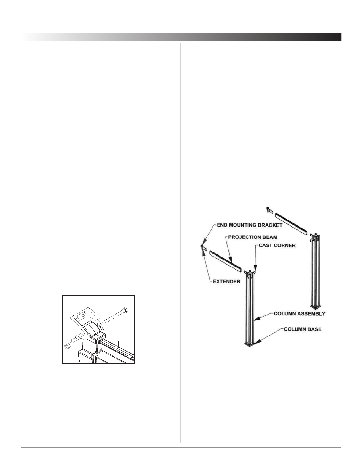
Step 11 Connect outside Projection Beams
Bungalow systems that are attached to a house or building
will have an notch on the Extenders that allow for the insertion
of the canopy rollers. On free-standing systems, Pro ection
Beams have notches cut in the tracks that allow for the
insertion of the canopy rollers. The outside Pro ection Beams
are notched on one side only; the side of the beam that is not
notched faces outside of the structure and the side that is
notched faces inside. The Pro ection Beams that are notched
on both sides go on the inside of the structure.
Remove the Extender from the End Mounting Bracket on the
wall. Assemble the outside Pro ection Beam by inserting the
arm of the Corner Bracket and the arm of the Extender into the
Pro ection Beam.
To help secure the Pro ection Beam during the assembly
process, insert two 7/8” tapping screws (A) into the Pro ection
Beam through both the Extender and the Corner Bracket.
Step 9 Temporarily Attach Extenders
Attach an
Extender
to each the two OUTSIDE End
Mounting
Brackets
on the house using the 2-3/4” bolts (F) and nuts (G)
provided. Be sure the top of the
Extender
is up (as shown.)
Loosely hand-tighten the nuts.
End Mounting Bracket
F
Extender
G
ShadeTree®Canopy Systems Assembly Instructions
The Bungalow
ShadeTree Cool Living, LLC — For questions or assistance call 800-894-3801 .7
Step 10 Attach a Projection Beam/Column Assembly
to the Wall Bracket
Attach one
Pro ection Beam/Column Assembly
to one of the
outside End
Mounting Brackets
on the house using the 2-3/4”
bolts (F) and nuts (G) provided. Be sure the top of the
Extender
is up (as shown.) Loosely hand-tighten the nuts.
Step 7 Assemble the Columns
Each Bungalow Aluminum Column consists of 4 panels that
simply snap together. Lay down a panel on a clean smooth
surface with the channel and ridge side facing up. Position a
second panel that has a notch so that the channel of the
second is over the ridge of the first panel. Using a rubber
mallet, gently hammer the edge of the second panel so the
ridge of the first locks into the channel of the second. Slide
the bottom of the two assembled panels into position in the
column base.
Repeat the process above with a third and fourth panel (one
with and one without a notch). Then stand upright the
second set of assembled panels and put around the post but
do not insert into base yet. Slide the bottom of the second set
of assembled panels into position in the column base.
Starting from the bottom of the column, snap together the
first and second sets of assembled panels; stop when you get
half way up the column. Get on a ladder above the Column
Assembly and use a rubber mallet to tap the top of the second
set until it slides into place and the top of the Column
Assembly panels are aligned.
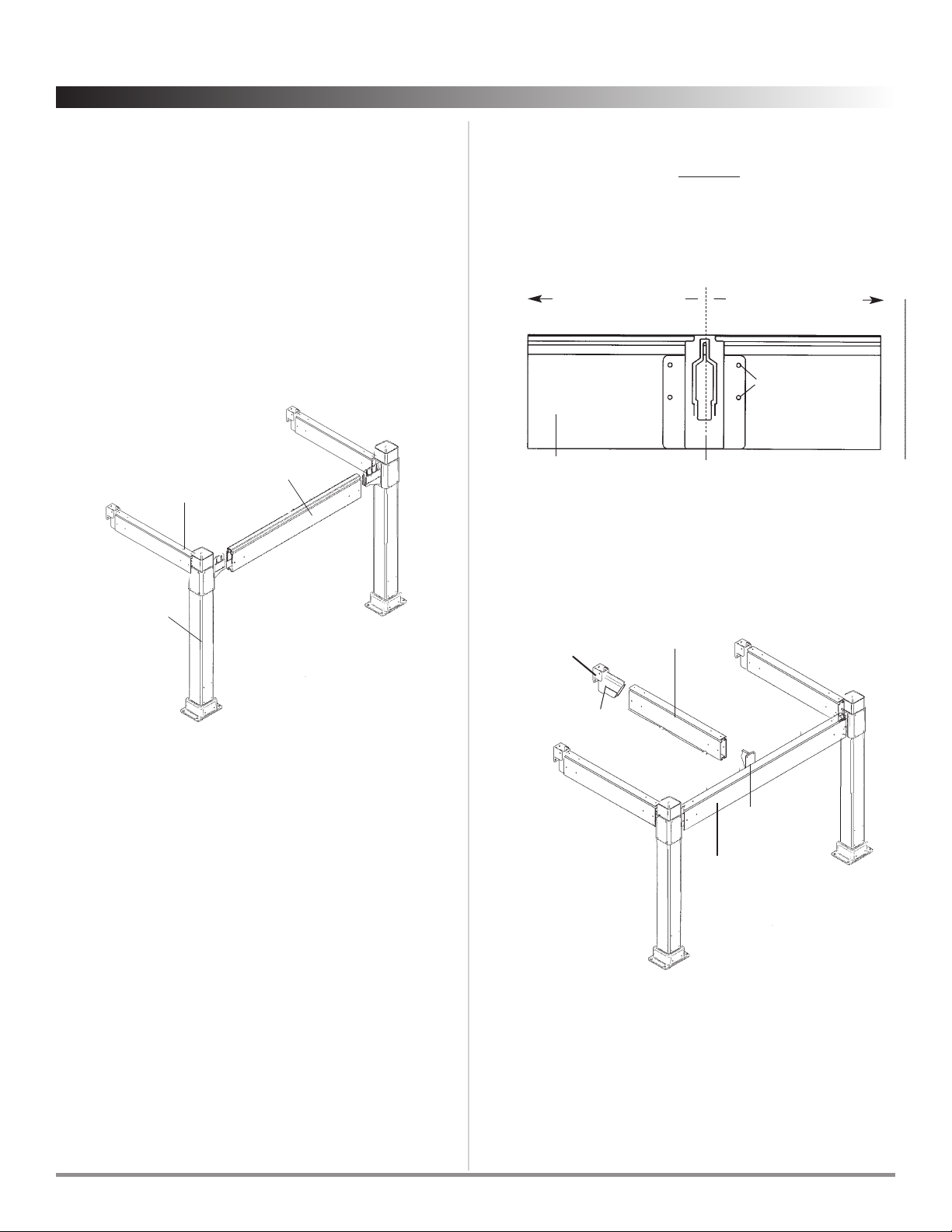
Measure inward from the centerline of the outside track 5’-4”.
Place the Mid-beam Bracket on the cross beam at this distance.
This location should be directly across from the End Mounting
Bracket on the house (step 1.) Secure the Mid-beam Bracket in
place with four 7/8” Tapping Screws (A).
Step 14 Assemble Mid-beam Bracket
eader beam Mid-beam Bracket
5’-4” to centerline
of outside track. See CAD
5’-4” to centerline
of outside track. See CAD
Mounting holes
Insert the arm of the Extender and the arm of the Mid-beam
Bracket into the Middle Pro ection Beam. Secure the beam by
inserting two 7/8” Tapping Screws (A) into the beam at each end.
Step 15 Connect Middle Projection Beam
Mid-beam
Bracket
Middle
Projection Beam
Extender
End Mounting
Bracket
eader
Beam
ShadeTree Cool Living, LLC — For questions or assistance call 800-894-3801 .
8
The Bungalow
ShadeTree®Canopy Systems Assembly Instructions
Lift the Column Base and use something to prop it up while you
position the Base Plate(s). Once in position pre-drill the holes and
then secure the Base Plate(s) with the screws. Then put the
Column Base back into it’s place at the bottom of the column.
Step 16 Connect Column Base Plates
Insert the arm on the Corner Bracket of the attached Pro ection
Beam/Column Assembly into the end of the Header Beam.
Attach the other Pro ection Beam/Column Assembly to the End
Mounting Bracket on the wall.
To secure the Header Beam, screw two 7/8” Tapping Screws
(A) through the pre-drilled holes on the top of the Header
Beam into the Corner Brackets at both corners.
Step 12 Connect Column Assemblies
eader
Beam
Projection
Beam
Column
Assembly
Step 13 Check to make sure the Assembled Outer
Frame is SQUARE
Measure the distance from one
Pro ection Beam/Column
Assembly
to the opposite outside End
Mounting Bracket
on the
house. Then measure the distance from other
Pro ection
Beam/Column Assembly
to the opposite outside End
Mounting
Bracket
on the house. Both measurements must be the same
for the system to be considered square. You must make any
necessary adjustments to ensure that it is square before
permanently anchoring the Columns.

ShadeTree®Canopy Systems Assembly Instructions
The Bungalow
ShadeTree Cool Living, LLC — For questions or assistance call 800-894-3801 .9
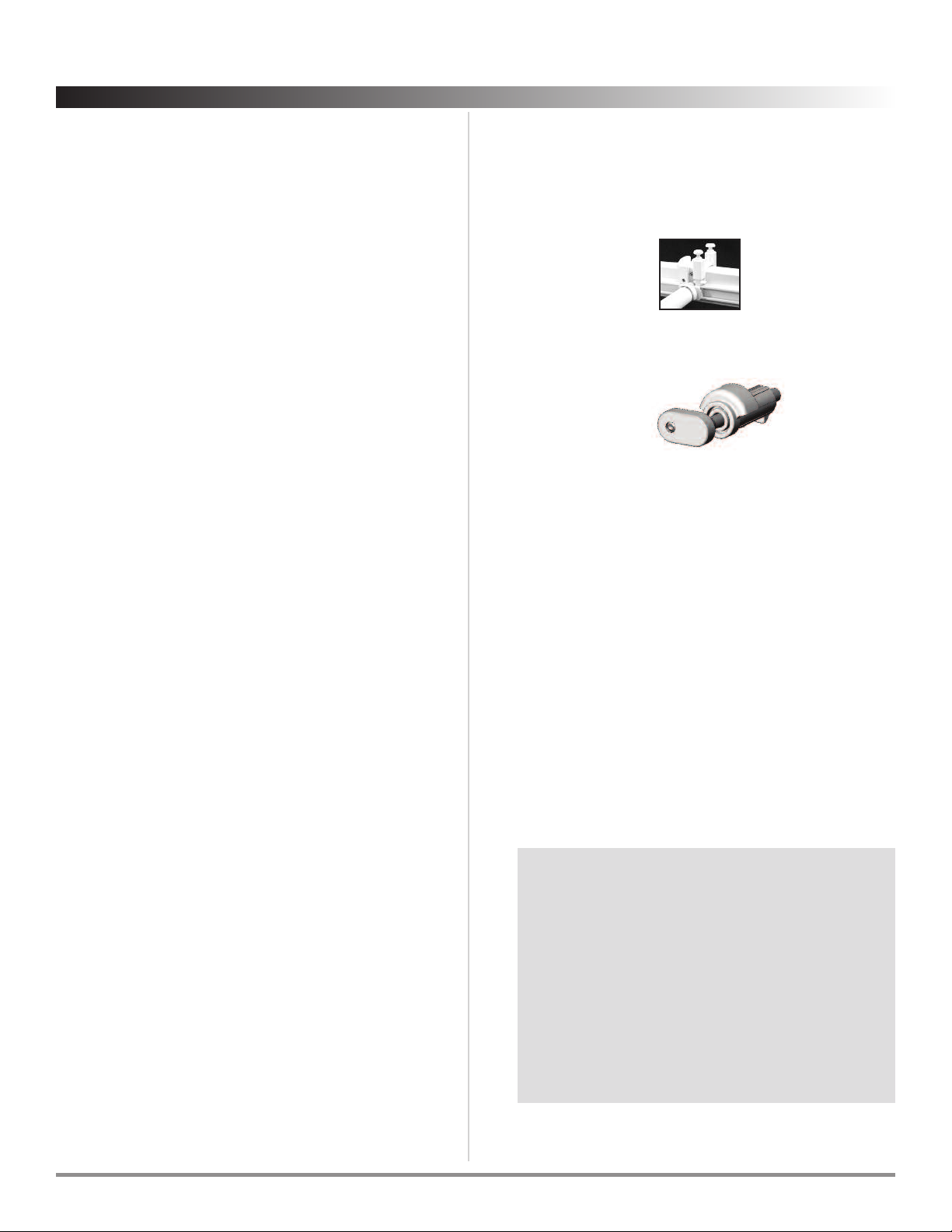
Step 17 Installing the Canopies
You can now insert the Canopies, starting at the end of the
beams closest to the house. Insert the Rollers at the ends of
each Cross Member; insert the front Cross Member first. The front
Cross Member is the one that has a Slide Lock on each end.
When inserting, ensure that the Lock Tab is pointing up as
shown here. Be sure that the canopy is oriented so that the
Fabric Clamp is facing up as shown, while the aluminum Cross
Member is oriented down. Continue inserting the remaining
rollers until the entire Canopy is up. Install remaining Canopies
using the same procedure.
Step 18 Locking the end of the canopy
Fabric
Clamp on
Front Cross
Member
Lock Tab
(Tab must
point upward)
Slide
Lock
Roller
If existing obstacles (casement
windows, doors, etc.) keep canopies
from retracting against the house,
extra canopy roller lock pins can be
put into the next rollers on the
canopies. As a result, canopies will
retract only to the desired position,
clearing the obstacle. It will be necessary to insert a grommet
hole in the locked out panel to allow the rain to drain.
A
Roller Lock Pin
is provided to hold the
Cross Member
nearest
the house in a fixed position. It will arrive already inserted in
the canopies in the last cross member. Once in place, it can
be secured with set screws. The locking pin will hold the last
Cross Member firmly in place. Repeat on each track. (On
masonry houses, it is
necessary to leave a few
inches between the canopy
and the house to prevent
scuffing of the canvas
during windy weather).
Roller
Lock Pin
Back/End
Top Cross
Member
Pull each canopy section out to the position where you want it to
end. Place a
Top Lock Bracket
on the top of the track in the
orientation shown in Fig. 2A. Tighten set screw 1 on both sides of
the
Top Lock Brackets
with the Allen wrench provided (I) . . .
making sure that the
Top Lock Brackets
are completely pushed
down on the track before tightening.
Test the snap-in Top Lock Bracket and tighten or loosen the
adjusting screws as required for the desired tension. The
recommended tension setting procedure is to turn the adjust
screw clockwise until it stops, and then back the adjust screw out
six full revolutions Repeat this step on each lock mechanism.
Step 19 Installing the Top Lock Brackets
Pull each canopy back to the fully retracted position. Place
another
Top Lock Bracket
on each track at this point, in the
orientation shown in Fig. 2A. Tighten the set screws.
OTE: The locking system is designed to release the canopies in
high winds to protect the canopies. The adjusting screws can be
used to adjust the tension. Do not over-tighten, as this could
increase the chance for canopy damage in high winds.
Adjusting
screws Stop
Stop set
screw
Set
screw 1
To posts To house
FIG 2-A
Step 20 Adjusting the handle height (optional)
Each canopy has the handle overhang approximately 18” from
the tracks. This drop handle is for opening and closing the
canopies. owever, if you must have less than an 18” overhang,
follow the instructions below for shortening the handle.
1. Remove all screws in the handle and open the
handle the entire width.
2. Cut the fabric to the desired length.
3. Carefully close the handle and re-insert the screws
provided - do not overtighten.
4. Reinstall the top caps in the end of the handle.
ShadeTree Cool Living, LLC — For questions or assistance call 800-894-3801 .
10
The Bungalow
ShadeTree®Canopy Systems Assembly Instructions
ow to remove ShadeTree®Canopies
for end-of season storage:
1. Remove the Top Lock Brackets at the “retracted” end of
each track (see step 16.)
2 Remove the Roller Lock Pin which holds the last Cross
Member in a fixed position (see step 15.)
3. Then simply roll the Cross Members out of the “retracted”
end of the track. The tracks can remain up year-round.
4. If a canopy is dirty and requires washing before storage,
simply spread the canopy on a driveway or other flat
surface. Wash, using a broom and bucket of warm water
and a mild soap, such as Ivory Snow.
Be sure to rinse well by hosing with a clear water. Allow to
air-dry completely in the sun before rolling canopies up for
storage. (Do not store wet canopies!)
ere’s a chance to earn $50!
We regularly use pictures in our advertising materials. If
you send us reproducible pictures of your new
ShadeTree®canopy installation, and we use them in any
of our advertising, we will send you $50. Interesting
before-and-after pictures will receive an additional $50.
Of course, attractive landscaping and patio furniture
will be a factor in selecting pictures to be used.
Architects, builders and installers will receive credit
mentions in the advertising.
Care and cleaning of your ShadeTree®Canopies
1. ShadeTree®tracks should be cleaned regularly to keep
debris and dirt from accumulating and interfering with
the rollers. Simply use a mild detergent with a small soft
brush, such as a toothbrush, and gently wipe or brush
along the inside of the tracks. To maintain a smoothly
operating system, apply a paste car wax such as KitTMor
TurtlewaxTMto the roller tracks. Allow the wax to dry then
wipe off with a clean, soft cloth. ote: Do OT use oil or
any wet lubricant, such as WD-40, on the tracks as it
would attract more dirt. For ultimate performance, use
ShadeTree®EasyRider Track Lubricant.
2. Fabric should be cleaned regularly before substances such
as dirt, roof particles, etc., are allowed to accumulate on
and become embedded in the fabric. The fabric can be
cleaned without being removed from the cross members.
Simply brush off any loose dirt, roof particles, etc.; hose
down and clean with a mild natural soap in lukewarm
water (no more than 100º F.) Rinse thoroughly to remove
soap. DO NOT USE DETERGENTS! For ultimate
performance, use ShadeTree®Canopy Cleaner Mold &
Mildew Stain Remover.
3. For stubborn stains soak the fabric for approximately 20
minutes in a solution of no more than 1/4 cup (2 oz.)
natural soap per gallon of water at approximately 100º F.
Rinse thoroughly in cold water to remove all of the soap.
Note: Excessive soaking in bleach can deteriorate sewing
threads. This method of cleaning may remove part of the
water repellency and the fabric should receive an
application of an air-curing water-repellent treatment,
such as APCO, UNISEAL, SUNSEAL or similar products, if
water repellency is a factor. For ultimate performance, use
ShadeTree®Canopy Cleaner Mold & Mildew Stain
Remover and ShadeTree®Water Repellent.
4. When washing or cleaning, DO NOT SUBJECT TO
EXCESSIVE EAT as the fabric will shrink. DO NOT STEAM
PRESS OR DRY IN ELECTRIC OR GAS DRYERS, but allow to
air dry.
5. In cases where canopies are taken down & stored, they
should be cleaned and allowed to air dry, before being
stored in a dry, well ventilated area.
Other ShadeTree Tent manuals


Popular Tent manuals by other brands


RioOutdoors
RioOutdoors 6F-DC installation instructions

Tentandtable.com
Tentandtable.com 40 Hex Assembly instructions

Big Sky
Big Sky Wisp 1P Moon View quick start guide

Khyam
Khyam AIRTEK KAMPER PRO 1 Pitching & Striking Instructions

Coleman
Coleman SKYDOME 9392-513 instructions

toolport
toolport economy 3x9 m Series Assembly instruction


