ShadeTree The Greenbriar User manual

Dear Customer:
Thank you for purchasing our ShadeTree®Canopy System. We trust these assembly
instructions will be satisfactory for your installation. If you have any questions, please feel
free to call 1-800-894-3801.
And here’s a special offer we’d like to make to you: Send us a photo of your new
ShadeTree®installation and we will send you $50 if we use your photo in our advertising
materials. Before and after pictures will receive an additional $50. A deck or patio that is
nicely furnished helps us communicate to prospective customers how nice a ShadeTree®
patio can be.
We hope you enjoy your new ShadeTree®patio canopies.
Sincerely,
Colin LeVeque, President
ShadeTree Cool Living, LLC.
2012
The Greenbriar
Using ShadeTree®Vinyl Overhead Tracks supported by a
vinyl support structure with fixed - post placement.
ShadeTree®Canopy Systems Assembly Instructions
ShadeTree Cool iving, C |6317 Busch Blvd. |Columbus, Ohio 43229 |800-894-3801 |fax 614-844-5991 |www.shadetreecanopies.com
End
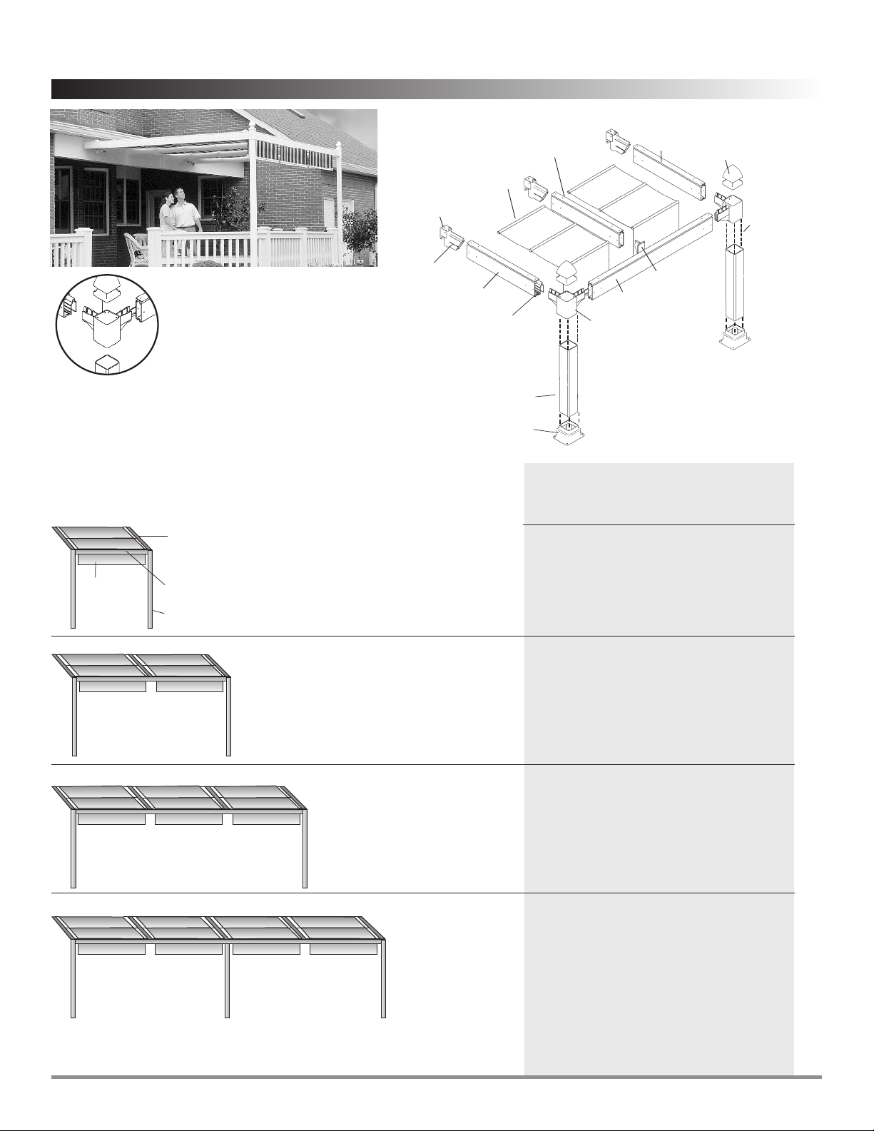
Mounting
Bracket
Extender
Post Base
Post
Fixed-post
Corner
Bracket
Mid- Beam
Bracket
Post Cap
Pre-assembled
Canopies
with rollers
Projection Beam
Aluminum
Support
Insert
1 canopy section
5’-4” or 4’-2-1/4” wide*
2 canopy sections
10’-8” or 8’-4-1/2” wide*
System Widths:
Parts for Vinyl ShadeTree®System
(utilizing fixed-post position support system)
Quantity
ShadeTree® Canopies 1
Corners 2
Extenders 2
Projection beams 2
Header beam 1
Posts (4” x 4” x 10’) 2
Posts – wood, 4” x 4” x 10’ ** 2
ShadeTree®Canopies 2
Corners 2
Extenders 3
Mid-Beam Position 1
Projection Beams 3
Header Beam 1
Posts (4” x 4” x 10’) 2
Posts – wood, 4” x 4” x 10’ ** 2
ShadeTree®Canopies 3
Corners 2
Extenders 4
Mid-Beam Position 2
Projection Beams 4
Header Beam 1
Posts (4” x 4” x 10’) 2
Posts – wood, 4” x 4” x 10’ ** 2
ShadeTree®Canopies 4
Corners 2
Extenders 5
Mid-Beam Position 2
Middle Position 1
Center Post-beam Hardware Kit 1
Projection Beams 5
Header Beam 2
Posts (4” x 4” x 10’) 3
Posts – wood, 4” x 4” x 10’ ** 3
Projection Beam
from house
Cross Beam
Posts
Canopy
4 canopy sections
21’-4” or 16’-9” wide*
4” x 4” wood
internal reinforcing
post – may be
imbedded into
ground for
added strength.
Purchased
separately.
** Purchased separately – should be longer if
to be imbedded into ground.
3 canopy sections
16’ or 12’-6-3/4”wide*
*Fixed-post Corner Bracket
with closed-ends provides a
finished look in standard, fixed
widths as shown below.
Header
Beam
Projection
Beam
Projection
Beam
*center to center of outside projection beams. Please allow an additional 8” overall to
accommodate mounting hardware and base fittings.
Complete Vinyl System
(supported by an vinyl frame)
All systems are custom-made and
shipped with the following kits
and parts included. This chart is
intended as a check-off list only.
ShadeTree Cool iving, C — For questions or assistance call 800-894-3801 .
2
The Greenbriar
ShadeTree®Canopy Systems Assembly Instructions
fixed-post placement
NOTE: You’ll find a second pair of hands (to hold parts as the
unit goes up) to be very helpful in erecting your vinyl system.
Other Materials Required:
You will also need 4” x 4” wooden posts for added
strength inside vinyl posts. Pre-selection of pressure-
treated wood is very important. Any warped or
oversized lumber will not fit inside the vinyl post. If
sinking posts into the ground, treated lumber is
recommended.
If mounting on a deck, patio, stepping stones, or
wooden landscaping timber embedded into the
ground, a wood post length of eight feet will suffice. If
you wish to cement the posts 3’ into the ground, 12’
posts are needed. The vinyl framework should be
completely assembled before cement is poured into
the holes.
If you are sinking posts into the ground, the four Post
Bases are optional. If you prefer to use the Post Bases,
they should be assembled onto the vinyl Posts before
erecting the system.
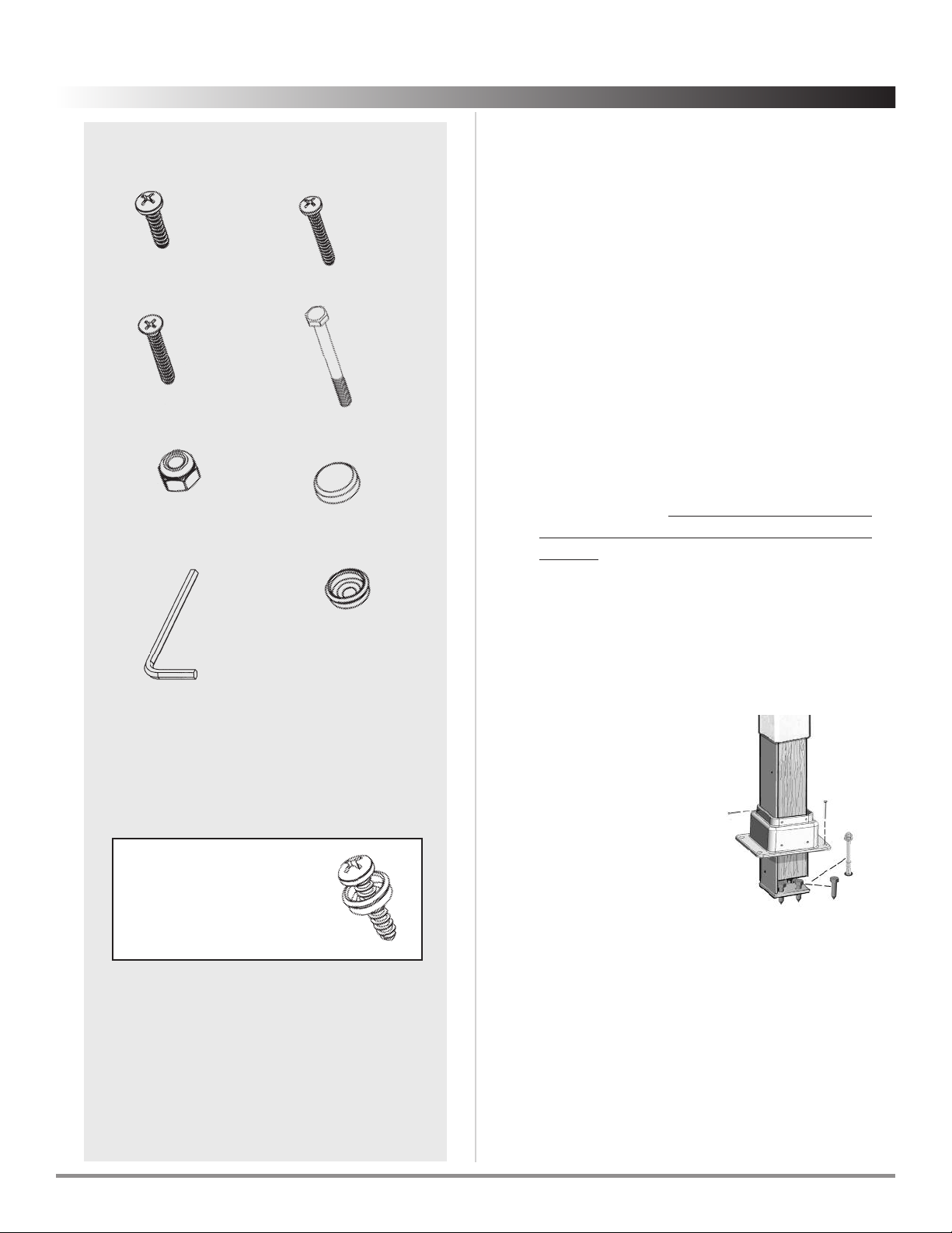
Fasteners & hardware provided:
Tools required:
1. Phillips screwdriver
2. Hand drill
3. 9/64” drill bit
4. pencil
5. bubble-type level
6. Carpenter’s square
7. tape measure
8. hand saw
9. 8’ ladder
7/8” Long
Tapping Screw 1-1/4” Long
Tapping Screw
Screw Cap
Washer
Nut
Allen Wrench
Screw Cap
2-3/4” Long
Bolt
Note: All A & B screws should
be assembled with screw cap
washer (D.) As shown at right.
A. B.
.
I. D.
E.
F.
If driving screws with a drill or power screwdriver, set the
torque to a low setting to avoid stripping screw heads.
1-1/4” Long
#10
Woodscrew
C.
Optional:
Internal Post Anchor Brac et
For use in securing vinyl
posts to concrete or decks,
when sinking wood posts in
the ground is not possible.
ShadeTree®Canopy Systems Assembly Instructions
The Greenbriar
ShadeTree Cool iving, C — For questions or assistance call 800-894-3801 .3
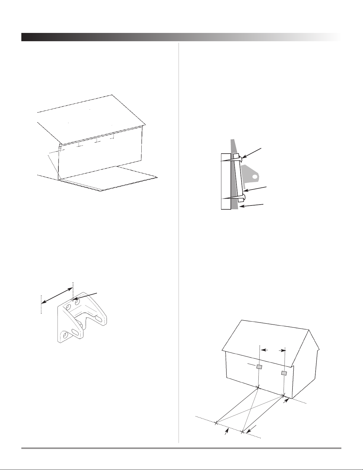
Mark the center location for each
End Mounting Brac et
on the
house 5-4” or 4’-2” apart. One
End Mounting Brac et
is needed for
every projection beam. Be sure to allow approximately 4” on the
outside of outermost brackets for inserting bolts into brackets.
Step 1 Attach End Mounting Brackets
Mount the
End Mounting Brac ets
on each center mark, using
the center notch as a guide. The brackets should be mounted
so that the the slanting edge of the bracket is to the top (as in
illustration). Be sure to mount the brackets level with each
other. Use a 9/64” drill bit to drill pilot holes. Wood screws are
included (1-1/4” screw c). . . any other type of screws (such as
masonry screws for brick or stone) can be purchased from
your hardware store. The Bracket can be used as its own
template for marking pilot holes.
5’4”
or
4’2-1⁄4”
5’4”
or
4’2-1⁄4”
5’4”
or
4’2-1⁄4”
4” min Screw or nail into
studs to support
1” x 4” board
Aluminum or
vinyl siding
1” x 4” board
Stud
When mounting to house, brac ets must be attached to
well-secured wood, bric or stone.
• If attaching to stucco, aluminum, or vinyl siding, the screws
must make contact with wood. On two story houses, this can
usually be done in the area of the second floor joists. When
no wood can be found to carry the canopy load, it is
recommended to attach a 1’’ x 4” board to the home (see
illustration below) . . . horizontally at the height desired for
the canopy. The board can then be secured by screws into
each stud. On aluminum or vinyl siding, tighten the bottom
screws only enough to hold board snugly. Over-tightening
can compress the siding. The board can be painted or
stained to match the siding.
• If mounting to a house with wood siding, or to wood trim,
use the 1-1/4” #10 wood screws with the painted heads
(screw c).
• If mounting to a masonry wall (brick or stone) concrete
fastening screws must be used. Consult your hardware
store for the best fastener for your situation.
Measure out from the house to the desired location of your first
vinyl Post (A). Measure out from the house a second time to the
location of your second vinyl Post (B). Be sure that points A & B
are on a line (C) that is parallel with the wall to which the End
Mounting Brackets are attached.
To ensure that your system will be square, measure the distance
from point B to point D. Then measure the distance from point
A to point C. Move points A and B right or left to get B to D and
A to C equal.
5’-4”
or 4’-21⁄4”
End
Mounting
Bracket
FIG 1-A
Line C
Step 2 Determine location of Posts
B
C
D
A
Post location
measurement
Center notch for 5’-4”
or 4’-2-1/4”alignment
Allow 2” beyond
center of bracket
2”
ShadeTree Cool iving, C — For questions or assistance call 800-894-3801 .
4
The Greenbriar
ShadeTree®Canopy Systems Assembly Instructions

Step 5 Attach Extenders
Attach an
Extender
to each of the End
Mounting Brac ets
on
the house using the 2-3/4” bolts (F) and nuts ( ) provided.
Be sure the top of the
Extender
is up (as shown.) Loosely
hand-tighten the nuts.
End Mounting Bracket F
Extender
It is important that your ShadeTree®structure be built on a
level surface. It is highly recommended that the vinyl & wood
posts be cemented 3’ into the ground.
Place one post Post Base in the desired location. Ensure that
this location is directly opposite the End Mounting Brac ets
you attached in step 1. Do not fasten to the mounting surface
at this time.
Step 3 Place One Post Base
If your application requires projection beams shorter than
provided, please follow step 7 on next page. If you are satisfied
with the projection length, proceed to step 8.
Step 6 Measure the length of the Projection Beams
Have your helper hold the Post Assembly square. Hold the
Extender level. Measure the distance from the Extender to the
Corner Brac et as shown in the illustration below. This
measurement will tell you exactly how long your Projection
Beams must be. Compare this measurement to the actual
length of the Projection Beams that you purchased to
determine how much needs to be cut (if any.)
Post
Base
Mounting
holes
(4)
Post location
measurement
Line C
5’4” center line
4” Minimum
Deck Edge
Step 4 Erect first Post
Slide a wood post into one vinyl Post and then insert one end
of that Post into the Post Base.
Drill eight 9/64” holes through the existing Post Base holes
into the wood post. Do not yet use the 1 1/4” Tapping Screws
(B) to tighten Post Base to Post.
Slip one Corner Brac et over the upper end of the first vertical
Post. Slide it down to the approximate desired height. To hold
the Corner Brac et temporarily in place until final leveling
adjustments are made, tighten the Corner Brac et set screw
using the Allen Wrench (I) provided.
Have your helper hold the post upright for the next step.
Vinyl
vertical
post
To house
Post
Base
Corner bracket
set screw to
temporarily hold
for leveling
Corner
bracket
*If cementing posts
into the ground, slide
the vinyl post about
12” up the wood post
and insert a wood
screw to hold in place.
Wood
Post
Screw
End
Mounting
Bracket
(on house)
Extender
Measured
projection
Corner
Bracket
Post
House
ShadeTree®Canopy Systems Assembly Instructions
The Greenbriar
ShadeTree Cool iving, C — For questions or assistance call 800-894-3801 .5

End
Mounting
Bracket
Extender
Post
Post Base
Corner
Bracket
Projection
Beam
Assemble the outside Projection Beam to the existing post
assembly.
Insert the arm of the Corner Brac et and the arm of the
extender into the Projection Beam. Ensure that the vertical
Post is square with the mounting surface and the Projection
Beam is square with the house. Slide the Post Base down to
the mounting surface and secure the Post Base to the Post
using the 1-1/4” Tapping Screw (B). You will be screwing into
the eight 9/64” holes you drilled in step 4.
To help secure the Projection Beam during the assembly
process, insert two 7/8” tapping screws (A) into the Projection
Beam through both the Extender and the Corner Brac et. The
two holes on the top of the track at the Extender connection
must be drilled into the Extender with the 9/64” drill bit to a
depth of approximately 1”.
Step 8 Connect outside Projection BeamsStep 7 Shorten Projection Beams (optional)
Cut the desired length off one end of the Projection Beam with
a hack saw or miter saw. It is recommended to cut the length
from the end of the Projection Beam closest to the house.
Ensure that the cut is square. Redrill the six mounting holes in
the end of the Projection Beam using the 9/64” drill bit. For the
holes on top of the Beam, measure along the scribed
centerline already present on the Beam. Drill the hole
locations per the dimensions shown below. For the holes on
the side of the Beam, drill four 9/64” holes per the dimensions
shown below. Repeat this process for all Projection Beams.
3/4”
from
end
3”
3/4”
from
end
3”
2-5/8”
Scribed centerline
Side hole
Vinyl Track
Aluminum
insert
2-5/8”
Repeat steps 5 through 7 for the other outside Projection
Beam. If cementing posts, square all vertical posts using a
bubble level. Add cement to holes & resume assembly once
cement is dry.
ShadeTree Cool iving, C — For questions or assistance call 800-894-3801 .
6
The Greenbriar
ShadeTree®Canopy Systems Assembly Instructions

If you have purchased a one-canopy system, skip steps 9 & 10.
Measure inward from the centerline of the outside track 5’-4”.
Place the Mid-beam Brac et on the cross beam at this distance.
This location should be directly across from the End Mounting
Bracket on the house (step 1.) Using the Mid-beam Brac et as
a template, mark the four mounting hole locations. Remove
the bracket and drill through one side of the Header Beam and
its aluminum insert with the 9/64” drill bit. Secure the Mid-
beam Brac et in place with four 7/8” Tapping Screws (A).
Step 10 Assemble Mid-beam Bracket
Header beam Mid-beam Bracket
5’-4” to centerline
of outside track.
5’-4” to centerline
of outside track.
Mounting holes
Insert the arm of the Extender and the arm of the Mid-beam
Brac et into the Middle Projection Beam. Secure the beam by
inserting two 7/8” Tapping Screws (A) into the beam at each end.
Step 11 Connect Middle Projection Beam
Mid-beam
Bracket
Middle
Projection Beam
Step 12 Fasten the system together
If the posts are cemented, remove the screw holding the vinyl
posts up and slide the vinyl posts backdown the wood posts.
Use a square and a level to make sure the posts are all square
and the beams are level. Proceed to insert screws into all
remaining fastening points. The quantity, type, and location of
all screws is shown below.
Be sure to use the plastic washer on each screw so a plastic cap
can be applied to cover the screw.
For a guide to screw hardware see page 3.
(4) C
(6) A
(6) A
(8) B
(6) A
(6) A
(8) B
(6) A
(6) A (8) B
(6) A
(6) A
Extender
End Mounting
Bracket
Header
Beam
(8) B
(4) C
Assemble the Header Beam to the Projection Beam/post
assembly. Have your helper hold one vertical Post in position
while you steady the 2nd vertical Post. Insert the arm on the
Corner Brac ets into the Header Beam on both ends.
Place a bubble level on top of the Header Beam to confirm
that it is level. If it is not, loosen the set screws on the Corner
Brac ets and lower or raise the Corner Brac ets on the Post as
necessary. Once level, drill eight 9/64” holes through the
existing mounting holes on the Corner Brac et and into the
Post. Fasten each corner with eight 1-1/4” Tapping Screws (B).
To secure the Header Beam, screw two 7/8” Tapping Screws
(A) through the pre-drilled holes on the top of the Header
Beam into the Corner Brac ets at both corners.
Step 9 Connect Posts
Header
Beam
Projection
Beam
Post Fixed-post positions
corner bracket
ShadeTree®Canopy Systems Assembly Instructions
The Greenbriar
ShadeTree Cool iving, C — For questions or assistance call 800-894-3801 .7
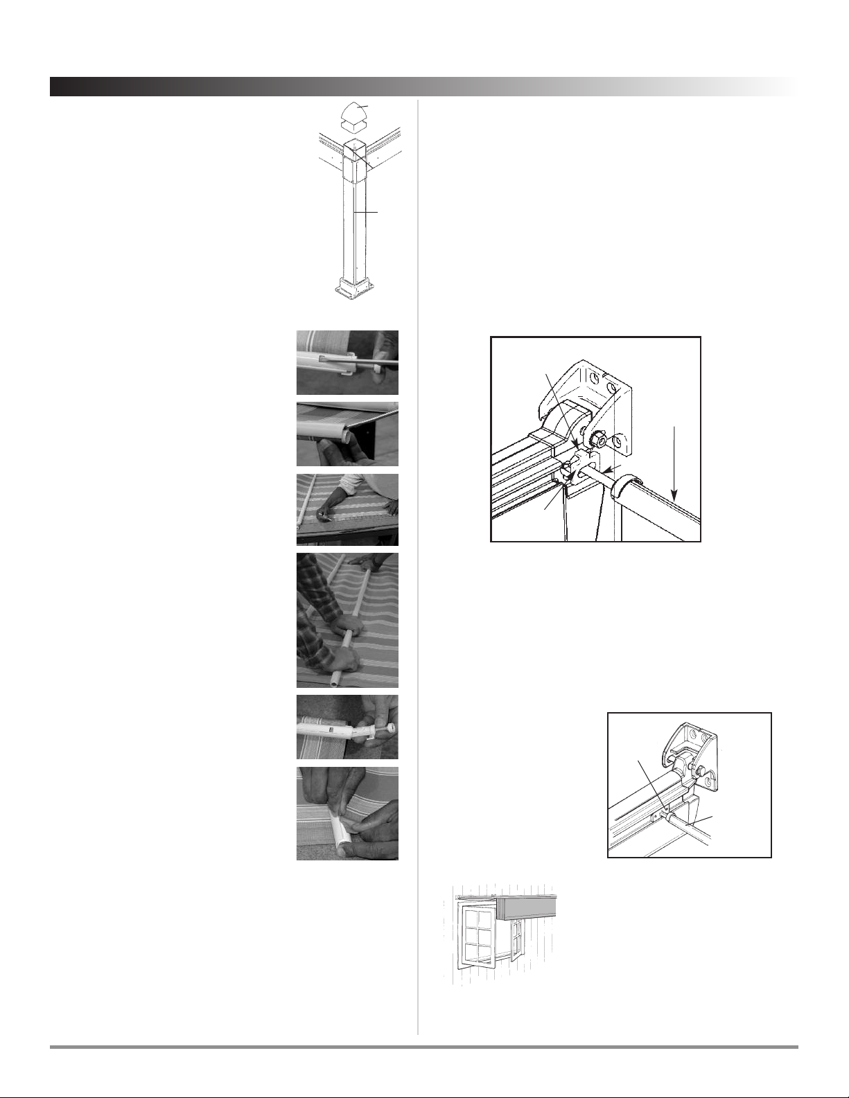
Step 13 Attach Caps to Posts
If more than 2” of Post is exposed above the
Corner Fitting, you can cut the excess with a saw
before assembling the Post Caps. Place one Post
Cap on top of each Post. If you wish to secure
the cap permanently on top of the Post, apply a
bead of clear silicon caulk (not provided) to the
inside wall of each cap before assembly.
Step 15 Installing the Canopies
You can now insert the Canopies, starting at the end of the
beams closest to the house. Insert the Rollers at the ends of
each Cross Member; insert the front Cross Member first. The front
Cross Member is the one that has a Slide Loc on each end.
When inserting, ensure that the Loc Tab is pointing up as
shown here. Be sure that the canopy is oriented so that the
Fabric Clamp is facing up as shown, while the aluminum Cross
Member is oriented down. Continue inserting the remaining
rollers until the entire Canopy is up. Install remaining Canopies
using the same procedure.
Step 16 ocking the end of the canopy
Fabric
Clamp on
Front Cross
Member
Lock Tab
(Tab must
point upward)
Slide
Lock
Roller
Post
Corner
Fitting
Post Cap
Step 14 Shortening Canopy ength (optional)
Lay the canopy on a flat clean surface. The
extra fabric length should be removed from
the back end of the canopy. This is the end
opposite the handle. Remove the Roller
Sleeve assemblies at both ends of the back
canopy Cross Member. To do this, first fully
extend the Roller, then push down on the
locking tab and pull Roller Sleeve outward
(Fig. 2A).
Remove the Fabric Clamp. To do this, insert
a flat head screw driver between the
canopy fabric and the Fabric Clamp. Pry
upward to release the Fabric Clamp (Fig. 2B).
From the back end of the canopy, measure
the same distance that was taken off the
track length. Make a mark at this distance
on both outside edges of the fabric (Fig. 2C).
Place the Bottom Cross Member (aluminum)
underneath the canopy, centering it on the
two marks. Position the Bottom Cross
Member so the punched square holes at the
ends are facing downward. Holding the
Bottom Cross Member in this position,
reassemble the Fabric Clamp by snapping
the Fabric Clamp in place at both ends and
pressing down, working toward the center .
Insert the Roller Sleeve assemblies back into the Bottom Cross
Member, ensuring that the locking tab engages the corresponding
punched square hole in the Bottom Cross Member (Fig. 2E).
Measure the canopies to ensure the desired length is correct
before trimming off excess canopy material. Remove the canopies
and place on a flat, clean surface. To remove the excess canopy
material, use the edge of the Fabric Clamp as a guide when cutting
with a sharp utility knife (Fig. 2F).
Fig. 2A
Fig. 2A
Fig. 2B
Fig. 2B
Fig. 2C
Fig. 2C
Fig. 2D
Fig. 2D
Fig. 2E
Fig. 2E
Fig. 2F
Fig. 2F
If existing obstacles (casement
windows, doors, etc.) keep canopies
from retracting against the house,
extra canopy roller locks can be
inserted into the tracks and hooked
onto the next rollers on the canopies. As a result, canopies will
retract only to the desired position, clearing the obstacle.
A
Roller Loc Pin
is provided to hold the
Cross Member
nearest
the house in a fixed position. It will arrive already inserted in
the canopies in the last cross member. Once in place, it can be
secured with set screws. The locking pin will hold the last Cross
Member firmly in place. Repeat on each track. (On masonry
houses, it is recommended
to leave a few inches
between the canopy and
the house to prevent
scuffing of the canvas
during windy weather).
Roller
Lock Pin
Back/End
Top Cross
Member
ShadeTree Cool iving, C — For questions or assistance call 800-894-3801 .
8
The Greenbriar
ShadeTree®Canopy Systems Assembly Instructions

Pull each canopy section out to the position where you want it to
end. Place a
Top Loc Brac et
on the top of the track in the
orientation shown in Fig. 2A. Tighten set screw 1 on both sides of
the
Top Loc Brac ets
with the Allen wrench provided (I) . . .
making sure that the
Top Loc Brac ets
are completely pushed
down on the track before tightening.
Test the snap-in Top Loc Brac et and tighten or loosen the
adjusting screws as required for the desired tension. The
recommended tension setting procedure is to turn the adjust
screw clockwise until it stops, and then back the adjust screw out
six full revolutions Repeat this step on each lock mechanism.
Step 17 Installing the Top ock Brackets
Pull each canopy back to the fully retracted position. Place
another
Top Loc Brac et
on each track at this point, in the
orientation shown in Fig. 2A. Tighten the set screws.
NOTE: The locking system is designed to release the canopies in
high winds to protect the canopies. The adjusting screws can be
used to adjust the tension. Do not over-tighten, as this could
increase the chance for canopy damage in high winds.
Step 18 Assemble Screw Caps
Locate the small white Caps (E) in the hardware packet and
snap the caps onto the screw cap washers (D).
Adjusting
screws
Stop
Stop set
screw
Set
screw 1
To posts To house
FIG 2-A
Step 19 Adjusting the handle height (optional)
Each canopy has the handle overhang approximately 18” from
the tracks. This drop handle is for opening and closing the
canopies. However, if you must have less than an 18” overhang,
follow the instructions below for shortening the handle
height.
1. Remove all screws in the handle and open the
handle the entire width.
2. Cut the fabric to the desired length.
3. Carefully close the handle and re-insert the screws
provided - do not overtighten.
4. Reinstall the top caps in the end of the handle.
ShadeTree®Canopy Systems Assembly Instructions
The Greenbriar
ShadeTree Cool iving, C — For questions or assistance call 800-894-3801 .9

Care and cleaning of your ShadeTree®Canopies
1. ShadeTree®tracks should be cleaned regularly to keep
debris and dirt from accumulating and interfering with
the rollers. Simply use a mild detergent with a small soft
brush, such as a toothbrush, and gently wipe or brush
along the inside of the tracks. To maintain a smoothly
operating system, apply a paste car wax such as KitTMor
TurtlewaxTM to the roller tracks. Allow the wax to dry then
wipe off with a clean, soft cloth. Note: Do NOT use oil or
any wet lubricant, such as WD-40, on the tracks as it
would attract more dirt. For ultimate performance, use
ShadeTree®EasyRider Track ubricant.
2. Fabric should be cleaned regularly before substances such
as dirt, roof particles, etc., are allowed to accumulate on
and become embedded in the fabric. The fabric can be
cleaned without being removed from the cross members.
Simply brush off any loose dirt, roof particles, etc.; hose
down and clean with a mild natural soap in lukewarm
water (no more than 100º F.) Rinse thoroughly to remove
soap. DO NOT USE DETER ENTS! For ultimate
performance, use ShadeTree®Canopy Cleaner Mold &
Mildew Stain Remover.
3. For stubborn stains soak the fabric for approximately 20
minutes in a solution of no more than 1/4 cup (2 oz.)
natural soap per gallon of water at approximately 100º F.
Rinse thoroughly in cold water to remove all of the soap.
Note: Excessive soaking in bleach can deteriorate sewing
threads. This method of cleaning may remove part of the
water repellency and the fabric should receive an
application of an air-curing water-repellent treatment,
such as APCO, UNISEAL, SUNSEAL or similar products, if
water repellency is a factor. For ultimate performance, use
ShadeTree®Canopy Cleaner Mold & Mildew Stain
Remover and ShadeTree®Water Repellent.
4. When washing or cleaning, DO NOT SUBJECT TO
EXCESSIVE HEAT as the fabric will shrink. DO NOT STEAM
PRESS OR DRY IN ELECTRIC OR AS DRYERS, but allow to
air dry.
5. In cases where canopies are taken down & stored, they
should be cleaned and allowed to air dry, before being
stored in a dry, well ventilated area.
How to remove ShadeTree®Canopies
for end-of season storage:
1. Remove the Top ock Brackets at the “retracted” end of
each track (see step 16.)
2 Remove the Roller ock Pin which holds the last Cross
Member in a fixed position (see step 15.)
3. Then simply roll the Cross Members out of the “retracted”
end of the track. The tracks can remain up year-round.
4. If a canopy is dirty and requires washing before storage,
simply spread the canopy on a driveway or other flat
surface. Wash, using a broom and bucket of warm water
and a mild soap, such as Ivory Snow.
Be sure to rinse well by hosing with a clear water. Allow to
air-dry completely in the sun before rolling canopies up for
storage. (Do not store wet canopies!)
Here’s a chance to earn $50!
We regularly use pictures in our advertising materials. If
you send us reproducible pictures of your new
ShadeTree®canopy installation, and we use them in any
of our advertising, we will send you $50. Interesting
before-and-after pictures will receive an additional $50.
Of course, attractive landscaping and patio furniture
will be a factor in selecting pictures to be used.
Architects, builders and installers will receive credit
mentions in the advertising.
ShadeTree Cool iving, C — For questions or assistance call 800-894-3801 .
10
The Greenbriar
ShadeTree®Canopy Systems Assembly Instructions
Other ShadeTree Tent manuals


Popular Tent manuals by other brands

Zempire
Zempire GROUND SHEET instructions

E-Z UP
E-Z UP Instant Shelter Endeavor owner's manual

may SCHIRM-SYSTEME
may SCHIRM-SYSTEME Albatros installation instructions

Vaude
Vaude TAURUS 2P user manual

Skandika
Skandika Freeland manual

Joyside
Joyside 11 Ft x 11 Ft Pop Up Canopy with Netting instruction manual


