Shadin Avionics AIS-380 User manual


DOCUMENT
AIS-380 Fuel Flow Adapter
Control SC1
INSTALLATION MANUAL
Revision C
M833811-01
Page: 2 of 30
SHADIN AVIONICS
www.shadin.com Customer Service: (952) 836-2269 service@shadin.com
REVISION LOG
Rev Date ERN DESCRIPTION
–
22 JAN 2016
1509/004
Baseline Release
A
16 OCT 2018
1810/004
Corrected typo bit 29 on page 8
B
15 JAN 2019
1901/001
Updated table 1 and deleted Bell 412 EPI Installation
C
23 JAN 2020
2001/009
Added bonding section, section 5 clarification and updated
company address
digitally signed
by ShadinCM-zk
2020.01.24
11:36:45 -06'00'

DOCUMENT
AIS-380 Fuel Flow Adapter
Control SC1
INSTALLATION MANUAL
Revision C
M833811-01
Page: 3 of 30
SHADIN AVIONICS
www.shadin.com Customer Service: (952) 836-2269 service@shadin.com
TABLE OF CONTENTS
1OVERVIEW .....................................................................................................................5
1.1 SCOPE ..............................................................................................................................5
1.2 PRODUCT DESCRIPTION................................................................................................ 5
2SPECIFICATIONS...........................................................................................................6
2.1 PHYSICAL.........................................................................................................................6
2.2 ELECTRICAL..................................................................................................................... 6
2.3 FUNCTIONAL....................................................................................................................6
2.3.1 INPUTS:.....................................................................................................................................6
2.3.2 OUTPUTS:.................................................................................................................................6
2.3.3 AIRDATA AND HEADING CONVERSION (OPTIONAL) ..........................................................8
2.4 ENVIRONMENTAL ............................................................................................................ 8
2.5 SOFTWARE CERTIFICATION........................................................................................... 9
2.6 REGULATORY CERTIFICATION...................................................................................... 9
2.7 RELIABILITY...................................................................................................................... 9
2.8 ACCURACY.......................................................................................................................9
3INSTALLATION.............................................................................................................10
3.1 LIMITATIONS .................................................................................................................. 10
3.2 INCOMPLETE SYSTEM.................................................................................................. 10
3.2.1 PERFORMANCE STANDARDS..............................................................................................10
3.3 MOUNTING ..................................................................................................................... 10
3.4 ELECTRICAL CONNECTION.......................................................................................... 10
3.4.1 TYPICAL INSTALLATION WIRING.........................................................................................11
3.4.2 DC TO FREQUENCY INSTALLATION EXAMPLE .................................................................12
3.4.3 GARMIN RECEIVER INSTALLATION EXAMPLE ..................................................................14
3.4.4 SINE TO SQUARE WAVE CONVERTER INSTALLATION EXAMPLE..................................15
3.5 BONDING........................................................................................................................ 15
3.6 REPAIR ........................................................................................................................... 15
4ENVIRONMENTAL QUALIFICATION FORM (EQF) ....................................................16
5CONFIGURATION TOOL..............................................................................................17
5.1.1 CONFIGURATION TOOL SOFTWARE INSTALLATION........................................................18
5.1.2 USING THE CONFIGURATION TOOL.....................................................................................21
6APPENDIX A: INSTALLATION DRAWING..................................................................26
7APPENDIX B: INSTALL KIT, PARTS LIST..................................................................29

DOCUMENT
AIS-380 Fuel Flow Adapter
Control SC1
INSTALLATION MANUAL
Revision C
M833811-01
Page: 4 of 30
SHADIN AVIONICS
www.shadin.com Customer Service: (952) 836-2269 service@shadin.com
LIST OF FIGURES
Figure 1 : AIS-380 Fuel Flow Adapter Overview.................................................................................................5
Figure 2 : Air Data Computer/Heading ARINC 429 to RS-232...........................................................................8
Figure 3 : Standard Fuel Flow Configuration................................................................................................... 11
Figure 4 : DC Fuel Flow Installation with P/N 630502 ..................................................................................... 12
Figure 5 : Garmin Receiver Installation............................................................................................................ 14
Figure 6 : Sine to Square Wave Converter Installation.................................................................................... 15
Figure 7 : Field Configuration Cable ................................................................................................................ 17
LIST OF TABLES
Table 1 – ARINC 429 Data I/O.............................................................................................................................7
Table 2 – DC Fuel Flow K-Factors.................................................................................................................... 13
Table 3 – Serial Output Formats....................................................................................................................... 24
DOCUMENT
AIS-380 Fuel Flow Adapter
Control SC1
INSTALLATION MANUAL
Revision C
M833811-01
Page: 5 of 30
SHADIN AVIONICS
www.shadin.com Customer Service: (952) 836-2269 service@shadin.com
1 OVERVIEW
The information in this manual is subject to change without notification.
1.1 SCOPE
This manual is intended to determine a proper installation of the AIS-380 FUEL FLOW ADAPTER. Installation
instructions should be read and followed.
1.2 PRODUCT DESCRIPTION
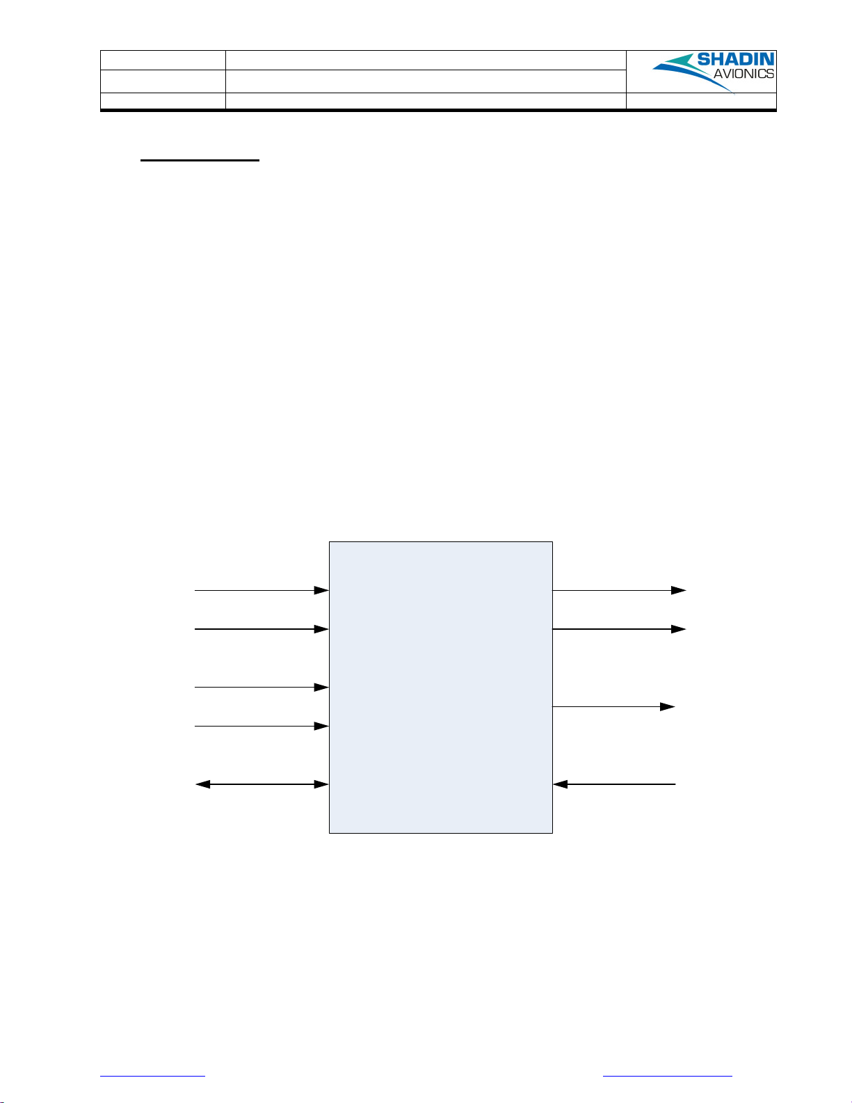
The AIS 380 Fuel Flow is a product designed to provide fuel flow on a digital output bus to a display or GPS
receiver that can receive ARINC 429 or RS-232. The AIS Fuel Flow receives a digital frequency signal from a
fuel transducer or equivalent, ARINC 429 air data, and ARINC 429 heading. The AIS Fuel Flow combines this
data and re-transmits it on an ARINC 429 or RS-232 serial output bus.
The ARINC 429 speed, K-factor, single/twin engine selection, fuel density, and serial output formats are
configurable using the PC based configuration tool referenced later in this installation manual.
A basic overview is shown below in Figure 1.
AIS-380
Fuel Flow Adapter
P/N 833811
ARINC 429
HS/LS Receiver 1
ARINC 429
HS/LS Receiver 2
ARINC 429
HS/LS Transmitter 1
ARINC 429
HS/LS Transmitter 2
SERIAL 1
RS-232
Maintenance
SERIAL 2
RS-232 Air Data/
Fuel Flow Data
Output
SERIAL 4
RS-422 Fuel Flow
Parameter Receiver
Pulse/Freq 1
Input
Pulse/Freq 2
Input
Figure 1 : AIS-380 Fuel Flow Adapter Overview
The features which are applicable to all standard installations are listed below:
•Two +12 VDC power supplies are available for powering fuel flow transducers
•ARINC 429 inputs are forwarded to the ARINC 429 outputs
•ARINC 429 speed (high or low) is configurable. Each ARINC 429 channel input and output speed is
matched when configured, e.g. ARINC 429 channel 1 input channel set for high speed results in
ARINC 429 channel 1 output set for high speed
•Fuel Flow labels 244 (Total Fuel Flow) and 347 (Left and Right independent Fuel Flow based on SDI)
are generated and output at an 8 Hz rate when configured for normal fuel flow format.
Other manuals for AIS-380
1
This manual suits for next models
1
Table of contents
Other Shadin Avionics Adapter manuals


