Shakespeare Electronic 9000100 User manual
32 lbs TROLLING MOTOR
MODEL: 9000100
Important: READ THIS MANUAL CAREFULLY BEFORE OPERATING YOUR
NEW SHAKESPERE TROLLING MOTOR. RETAIN FOR FUTURE REFERENCE
operator’s manual
toll-Free HelplIne: 1 866 456-8934
Powered by Greenworks
www.greenworkstools.com

2
PRODUCT SPECIFICATIONS..........................................................................................................................2
FUNCTIONS.....................................................................................................................................................3
ADJUSTMENTS........................................................................................................................................... 4-5
OPERATION.....................................................................................................................................................6
BATTERY & BATTERY CHARGER.............................................................................................................. 7-9
PROPELLER..................................................................................................................................................10
MAINTENANCE..............................................................................................................................................11
TROUBLESHOOTING................................................................................................................................... 12
WARRANTY....................................................................................................................................................13
EXPLODED VIEW..........................................................................................................................................14
PARTS LIST................................................................................................................................................... 15
TABLE OF CONTENTS
PRODUCT SPECIFICATIONS
9000100 (32 lbs)
Motor............................................................................................................................................................40V
Thrust.........................................................................................................................................................32lbs
Prop speeds................................................................................................................................200-1900 RPM
Forward speed.....................................................................................................................................5 speeds
Reverse speed.....................................................................................................................................3 speeds
Composite shaft............................................................................................................................................ 36"
Weight.................................................................................................................................................... 23.3lbs
NOTE: To be used with Greenworks Lithium-Ion Battery(Model# 29662).

3
FUNCTIONS
Shaft tilt release lever
Boat mounting bracket
Propeller
40V DC Motor
Adjustable shaft
Clamping knobs
Tilt/Twist tiller handle
Battery compartment
Depth collar knob
Steering tension knob
4
ADJUSTMENTS
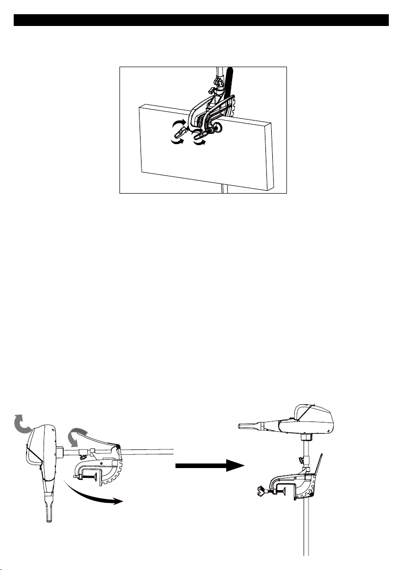
MOUNTING THE MOTOR:
Install the motor on the transom of the boat. Be sure to tighten the clamp screws securely.
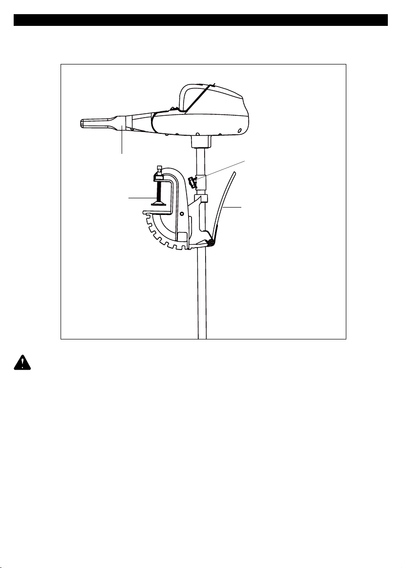
DEPTH ADJUSTMENT:
1. Firmly grasp the shaft and hold it steady.
2. Loosen the steering tension knob and depth collar knob until the shaft slides freely.
3. Raise or lower the motor to the desired depth.
4. Tighten depth collar knob to secure the motor in place.
IMPORTANT: WHEN SETTING THE DEPTH BE SURE THE TOP OF THE MOTOR IS SUBMERGED AT
LEAST 12" (30 cm) TO AVOID CHURNING OR AGITATION OF SURFACE WATER. THE PROPELLER
MUST BE COMPLETELY SUBMERGED.
CAUTION:
• NEVER OPERATE YOUR MOTOR WHEN IT IS OUT OF THE WATER.
• OVER-TIGHTENING THE CLAMP SCREWS CAN DAMAGE THE BRACKET
BRACKET ADJUSTMENT:
You can lock your motor in a vertical position, angle it for shallow water or tilt it completely out of the water.
•Firmlygraspthecontrolheadorshaft.
•Depressandholdthetiltlever.
•Tilttoanyofthepositionsonthemountingbracket.
•Releasethetiltlever.
Tighten
Loosen
5
ADJUSTMENTS
WARNING: WHEN MAKING ANY ADJUSTMENTS TO MOTOR OR PROPELLER THE BATTERY
MUST BE REMOVED FROM THE TROLLING MOTOR.
Tiller speed control
Shaft tilt release lever
Shaft depth adjustment collar
Clamping knobs
Table of contents


