Vox Valveronix ToneLab LE User manual

VOX ToneLab LE
Valvetronix
SERVICE MANUAL
TABLE OF CONTENTS
ASSEMBLY SKETCH:2
BLOCK DIAGRAM:3
SCHEMATIC DIAGRAM:4-7
TEST MODE: 8-17
PARTS LIST:18-19
Issued Dec.12, 2006
Ver.1


ToneLabLE TEST MODE
How to enter the TEST MODE
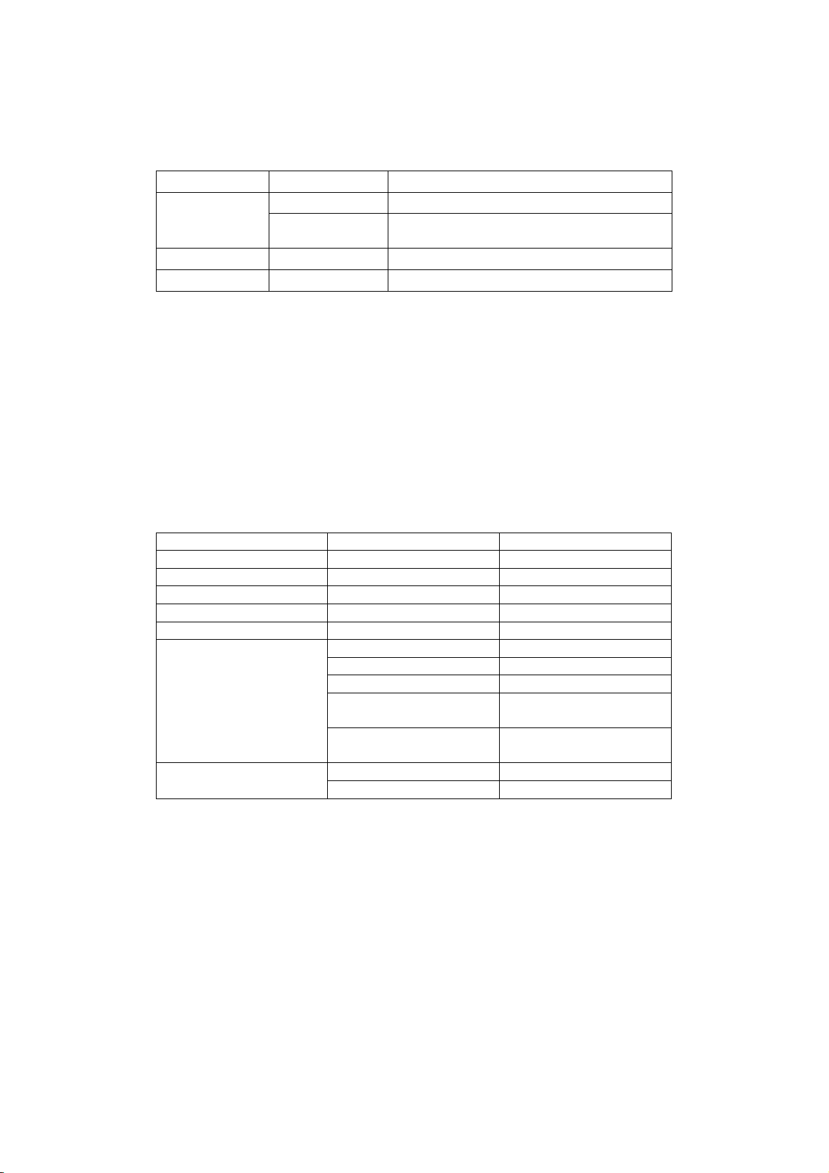
Pressing following switches and turn the power on.
“TONE LAB” and the version of the software are displayed, and after you removed fingers from the
switches, each TEST MODE will begin.
SWITCHES MODE
CUR_LEFT AMP/LINE Internal Check->Operation CheckInternal Check
CUR_LEFT RENAME Internal Check(Skipping terminal connection)
-> Operation Check
VACUUM TUBE ONLY CUR_UP RENAME VACUUM TUBE ONLY Check
MIDI Check CUR_DOWN AMP/LINE MIDI Check->AUDIO CHECK
Internal Check
Before the check connect from “PHONES” to “INPUT using the test cable 1 (described at the end
of this document), connect from “SEND” to “RETURN” using the test cable 2 (described at the
end of this document), and turn the “LEVEL” knob (next to the “PHONE output ) to maximum.
# When Internal Check (Skipping terminal connection), the Checks from 4.CODEC MUTE to 7.TUNER ( these
checks needs test cables1,2) are skipped,
Following Checks are executed automatically.
During the Check, the item number and the step number are displayed in the BANK LED.
When an NG occurred, the check is stopped with blinking the BANK LED and the check item’s name
is displayed in the LCD.
ITEM STEP DISPLAY WHEN NG
1. I2C I/F 1. EEPROM I2C EEP
2. DSP I/F 1. DSP DSP I/F
3. DSP SRAM 1.DATA BUS SRAM DAT
2.ADDRESS BUS SRAM ADR
4. CODEC MUTE 1. CODEC MUTE CODEC-MU
1. DSP(L) ---> DSP(R)NORMAL CH LVL L->R
2. DSP(L) ---> DSP(L)GAIN CH LVL L->L
3. DSP(R) ---> DSP(R)NORMAL CH LVL R->R
4. DSP(L) -> SEND -> RETURN ->
DSP(R)NORMAL CH
LVL RTN
5. LEVEL
5.(disconnect RETURN) DSP(R)
---> DSP(R)NORMAL CH
RET RMVE
1. TUNER HI TUNER HI6. TUNER
2. TUNER LO TUNER LO
After an error occurred, pushing the “INSERT” switch and push following switch to restart the
Check.
WRITE: Inspect again the NG step.
EXIT: Skip the NG step and inspect next step.
CUR_LEFT: Inspect again the NG item
CUR_UP: Skip the NG item and inspect next item.

After finished internal Check, TONELAB Le automatically goes to Operation Check.
Internal Check 4. CODEC MUTE
This item inspects the wiring of the CODEC and DSP (FXD03). Same setting as LEVEL Check (3.1),
check input level and confirm that mute is working (there is not input bigger than noise level).
Internal Check 5. LEVEL
Output 1khz sine wave from the DSP2 and inspect the returned signal level to the input.
The test cable 1 and 2 (described at the end of this document) are needed for connection.
PHONE->INPUT, SEND->RETURN
The routing, output level, input level (OK range) are followings.
1. L->R , RETURN SW Off
SO[1]L (0.250(=1/4)) ---> DSP SI[1]R (0.150858 +-20%)
A/D D/A
AK5381VTPA AK4384VTP
+-------+ +-------+
| Ain L | | AoutL |-------> PHONE L
IN ------------------->| Ain R | | AoutR |- - - -> PHONE R
| | | |
+----| DoutL | | Din L |<---+
+-|----| DoutR | | Din R |<-+ |
| | +-------+ +-------+ | |
| | | |
| | DSP(FXD03) | |
| | +---------------+ | |
| +-->| SI[1]L SO[1]L |-----|-+
+---->| SI[1]R SO[1]R |-----+
+---------------+
2. L->L , RETURN SW On
SO[1]L (0.063(=1/16)) ---> DSP SI[1]L (0.607623 +-20%)
INSERT(*0.56) A/D D/A
| | AK5381VTPA AK4384VTP
| | +-------+ +-------+
IN ---+(-->)+-- *16 -->| Ain L | | AoutL |-------> PHONE L
↑ | Ain R | | AoutR |- - - -> PHONE R
RETURN OPEN | | | |
+----| DoutL | | Din L |<---+
+-|----| DoutR | | Din R |<-+ |
| | +-------+ +-------+ | |
| | | |
| | DSP(FXD03) | |
| | +---------------+ | |
| +-->| SI[1]L SO[1]L |-----|-+
+---->| SI[1]R SO[1]R |-----+
+---------------+

3. R->R , RETURN SW Off
SO[1]R (0.250(=1/4)) ---> DSP SI[1]R (0.150858 +-20%)
A/D D/A
AK5381VTPA AK4384VTP
+-------+ +-------+
| Ain L | | AoutL |- - - -> PHONE L
IN ------------------->| Ain R | | AoutR |-------> PHONE R
| | | |
+----| DoutL | | Din L |<---+
+-|----| DoutR | | Din R |<-+ |
| | +-------+ +-------+ | |
| | | |
| | DSP(FXD03) | |
| | +---------------+ | |
| +-->| SI[1]L SO[1]L |-----|-+
+---->| SI[1]R SO[1]R |-----+
+---------------+
4. RET1 , RETURN SW On
SO[1]R (0.250(=1/4))---> SEND -- (*約 0.560)--> RETURN --> DSP SI[1]R (0.168961 +-20%)
INSERT(*0.56) A/D D/A
| | AK5381VTPA AK4384VTP
| | +-------+ +-------+
IN ---+ +-- *16 -->| Ain L | | AoutL |- - - -> PHONE L
| Ain R | | AoutR |-------> PHONE R
| | | |
+----| DoutL | | Din L |<---+
+-|----| DoutR | | Din R |<-+ |
| | +-------+ +-------+ | |
| | | |
| | DSP(FXD03) | |
| | +---------------+ | |
| +-->| SI[1]L SO[1]L |-----|-+
+---->| SI[1]R SO[1]R |-----+
+---------------+

5.When [RET RMVE] is displayed in the LCD, disconnect the plug from RETURN.
6. RET2 , RETURN SW On (internally RETURN is selected)
SO[1]R (0.5001(=1/2*16)) ---> DSP SI[1]R (0.338713 +-30%)
(OPEN) A/D D/A
SEND--->RETURN AK5381VTPA AK4384VTP
| +-------+ +-------+
| | Ain L | | AoutL |- - - -> PHONE L
IN ---+--------------->| Ain R | | AoutR |-------> PHONE R
| | | |
+----| DoutL | | Din L |<---+
+-|----| DoutR | | Din R |<-+ |
| | +-------+ +-------+ | |
| | | |
| | DSP(FXD03) | |
| | +---------------+ | |
| +-->| SI[1]L SO[1]L |-----|-+
+---->| SI[1]R SO[1]R |-----+
+---------------+
Internal Check 6. TUNER
The DSP outputs the sine wave signal and this item inspects the returned signal level to the INPUT
by CPU. The test cable1 is needed for the connection of PHONE-->INPUT.
1. 2217.461047Hz
2. 25.9565436Hz
Operation Check
In this Check, use the CUR_UP/CUR_DOWN to select the item, use the CUR_LEFT to return to the initial
display of the item (without during the switch Check).
When an error occurred you can start from the NG step using the WRITE switch.
Item Initial Display LED Initial Display LCD
1. Pedal trimmer adjusting All LEDs light, BANK LED meter display PDL_CLB
2. PEDAL Lower Switch BANK LED "PS" PDL_SW
3. Switch, LED All LEDs light, BANK LED rounding SW & LED
4. Binary Encoder BANK LED "E1" BIN ENC
5. Volume with 11 clicks BANK LED "C1" C11 KNOB
6. Volume without click BANK LED "A1" VOL KNOB
7. Pedal calibration BANK LED "P " PEDAL
8. LCD BANK LED "Lc" All light
9. Vacuum tube output adjusting
Check of the symmetricness
BANK LED meter TUBE TRM
10. Load Preset BANK LED 'P', all CH LEDs blinking RELOAD ?
After the last item’s check finished, TONELAB LE goes to normal mode. When “Er” is displayed
in the LED, some error has occurred.

Operation Check 1. Pedal trimmer adjusting "PDL_CLB"(LCD)
1. EXP PEDAL trimmer adjusting
1.1 Step on the pedal to maximum.
1.2 Using a driver (not metal), adjust the trimmer volume at the rear and pedal side, until
the value of lower right in the LCD display is around “110”.
1.3 Confirm that all BANK LEDs light.
1.4 Push the GLOBAL switch.
Operation Check 2. Pedal lower switch Check "PDL_SW"(LCD)
1. Pedal lower switch Check
1.1 When stepped on the pedal by more than 25kg weight, confirm that the EXP LED lights red.
1.2 When stopped the pressing on the pedal, confirm that the EXP LED lights green.
1.3 Try 1.1 and 1.2 several times.
1.4 Push the GLOBAL switch.
Operation Check 3. Switches and LEDs "SW & LED"(LCD)
1. Confirmation of all LEDs light.
Confirm that all LEDs light without BANK LED.
2. Confirmation of BANK LED (7seg-2digits) light one by one.
Confirm that A-H of the BANK LED1 (left) , A-H of the BANK LED2 light one by one.
After confirmation, push GLOBAL to proceed to the next step.
A
---
F| G |B
---
E| |C
--- ・H
D
3. Confirmation of all LEDs and all switches individually
This is a Check of LEDs and switches like following order.
Confirm that an object LED lights and other LEDs do not light, then push the object switch.
And the LED turned off and the next LED lights. In the BANK LED the switch should be push next
is displayed. After all switches’ check TONELAB Le goes to next check automatically.
LED BANKLED SW
INSERT 1 INSERT
PEDAL 2 PEDAL
AMP 3 AMP
CAB 4 CAB
MODULATION 5 MODULATION
DELAY 6 DELAY
REVERB 7 REVERB
EXP-CTL-CHAIN 8 EXP-CTL-CHAIN
All LEDs light 9 CUR_LEFT
All LEDs light 10 CUR_UP
All LEDs light 11 CUR_DOWN
All LEDs light 12 CUR_RIGHT

All LEDs light 13 AMP/LINE
All LEDs light 14 WRITE
All LEDs light 15 RENAME
All LEDs light 16 EXIT/TUNE
All LEDs light 17 GLOBAL
EDIT_PEDAL 17 GLOBAL
EDIT_AMP 17 GLOBAL
EDIT_CAB-OPTION 17 GLOBAL
EDIT_MODULATION 17 GLOBAL
EDIT_DELAY 17 GLOBAL
EDIT_REVERB 17 GLOBAL
EDIT_EXP-CTL-CHAIN 17 GLOBAL
VAULE_1(GAIN) 17 GLOBAL
VAULE_2(VR GAIN) 17 GLOBAL
VAULE_3(TREBLE) 17 GLOBAL
VAULE_4(MIDDLE) 17 GLOBAL
VAULE_5(BASS) 17 GLOBAL
VAULE_6(CH VOLUME) 17 GLOBAL
BANK_DOWN_RED 18 BANK_DOWN
BANK_UP_RED 19 BANK_UP
(Channel) 1_RED 20 (Channel) 1
(Channel) 2_RED 21 (Channel) 2
(Channel) 3_RED 22 (Channel) 3
(Channel) 4_RED 23 (Channel) 4
C0NTROL_RED 24 C0NTROL
Notice:* During check, push REVERB SELECT three times to exit the switch check and return to the
step1.
* NG occurs when detected the changing of the binary encoders (PEDAL,AMP TYPE).
Operation Check 4. Binary Encoder "BIN ENC"(LCD)
At the initial state “E1” is displayed in the BANK LED.
1. PEDAL TYPE select knob
* Adjust the knob at the top position (12:00), then rotate to clockwise.
* After one rotation and at the top position “E2” is displayed in the BANK LED.
2. AMP TYPE select knob
*Adjust the knob at the top position (12:00), then rotate to clockwise.
Notice:
*After started this check, when a switch pushed, the check stops and “SL” is displayed in
the BANK LED.
Operation Check 5. Volume with 11 clicks "C11 KNOB"(LCD)
1. MODULATION knob (Initial display BANK LED "C1")
From the MAX (right end) click of the MODULATION SELECT knob, the check begins like following
order. When the knob is already at the right end click, move one click once and set to
the right end click again.

*The dot of the BANK LED lights, then rotate to the next click.
*After the left end click was finished, the check proceeds to the next step.
2. DELAY SELECT knob (initial display BANK LED "C2")
Do the check same as the MODULATION SELECT knob. After finished, the check proceeds to the next
step.
3. REVERB SELECT knob (initial display BANK LED "C3")
Do the check same as the MODULATION SELECT knob. After finished, the check proceeds to the next
step.
Notice: *Pushing the INSERT switch, push WRITE and EXIT to move to the next step.
3. REVERB SELECT つまみ (初期表示は BANK LED "C3")
Operation Check 6. Volume A/D "VOL KNOB"(LCD)
1. Rotate the GAIN knob to the MAX (right end), confirm that the dot of the BANK LED lights.
2. Rotate the GAIN knob to the MIN (left end).
3. Same as 1 and 2, do following check of all knobs.
Knob BANK LED
1. FX VALUE 1 (GAIN) A1
2. FX VALUE 2 (VR GAIN) A2
3. FX VALUE 3 (TREBLE) A3
4. FX VALUE 4 (MIDDLE) A4
5. FX VALUE 5 (BASS) A5
6. FX VALUE 6 (CH VOLUME) A6
Notice: Pushing the INSERT switch, push WRITE, EXIT to move the step.
Operation Check 7. Pedal calibration "PEDAL"(LCD)
1. EXP pedal calibration
1.1 Set the EXP PEDAL to the Mini side and push GLOBAL.
1.2 Set the EXP PEDAL to the Max side, confirm [-] in the LED.
1.3 Set the EXP PEDAL to the Mini side, confirm [=] in the LED.
1.4 Move the EXP PEDAL for several times and confirm that the display is [127] at the Mini,
[0] at the Max, and an error does not occur.
1.5 Push GLOBAL.
Operation Check 8. LCD all segments ON (LCD)
1. Confirm that all segments of the LCD turned ON, then push GLOBAL.
2. Confirm that all segments of the LCD turned OFF, then push GLOBAL.
3. Confirm that all segments of the LCD are blinking, then push GLOBAL.
Operation Check 9. Adjusting of the output of the vacuum tube, and symmetricness check
1. Waiting for heat-running of the vacuum tube
Wait for one minute from the power on, after one minute the check starts.

2. Adjusting of the output level
Adjust the trimmer volume at the rear and near the vacuum tube side until the BANK
LED becomes OK (LCD: 68**-6D**), after one second the BANK LED all light.
Push GLOBAL and proceed to the next step. Even if it was not OK, you can step up when
the value is in the range of 46**-66**.
BANK LED Left Right
| | too small
| | | | OK (after one second all turn on)
| | Too big
The vacuum tube output level (DSP input) level is displayed in the 7 segments of the
LCD. (Upper 16bits of 24bits= max7FFFFF )
3. Symmetricness check
The check is done automatically after displaying of “SYMM CHK”. When an error occurred
the check stops displaying “tu” in the BANK LED with blinking. At this error state, push CUR_LEFT
to return to the step2.
Operation Check 10. LOAD PRESET "RELOAD ?"(LCD)
This makes all data of the EEPROM to return to the status of the factory settings.
Push GLOBAL, then the reloading begins, the program number is displayed in the BANK LED
and the CH LED. When succeeded, "COMPLETE"(LCD) is displayed for one second and TONELAB
automatically goes to the normal mode. When failed, TONELAB stops displaying "MEM ERR"(LCD).
MIDI CHECK (INTERNAL CHECK 7.)
Before this check connect MIDI IN and MIDI OUT using a MIDI cable.
After finished, the check proceeds to Audio Check automatically.

Audio Check MODE (External check 8)
This is the bypass mode which the signal of input is sent to the output (including HEAD PHONES,
S/P DIF).
The step is changed by CH3 and CH4. The signal route and the circuit setting are different by the
step.
STEP BANK LED LCD Routing
(DSP Mode, Return, Level L->L, R->L, L->R, R->R)
1 “b1” D R-LR For Output circuit check(Digital Thru, Return=Off, 0,1,0,1 )
(L)=> D/A=> L OUT
NORM CH(R)=> A/D=> DSP(R)=> D/A=> R OUT
2 “b2” D S R-LR For RETURN circuit check ( Digital Thru, Return=ON, 0,1,0,1 )
(L)=> D/A=> L OUT
NORM CH(R)=> SEND => RETURN => A/D=> DSP1(R)=> D/A=> R OUT
3 “b3” D LR-LR For Input circuit check (Digital Thru, Return=Off, 1,0,0,1 )
GAIN CH(L)=> A/D=> DSP(L)=> D/A=> L OUT
NORM CH(R)=> A/D=> DSP(R)=> D/A=> R OUT
4 “b4” A CLS A For vacuum tube circuit check (Analog Thru, Return=Off, 0,1,0,1)
(Class A, FeedBack=off, Resonance=off)
(L)=> D/A=> TUBE=> A/D=> DSP=> D/A=> L OUT
NORM CH(R)=> A/D=> DSP(R)=> D/A=> THRU=> A/D=> DSP=> D/A=> R OUT
5 “b5” A CLS AB For vacuum tube circuit check (Analog Thru, Return=Off, 0,1,0,1)
(Class AB, FeedBack=off, Resonance=off)
(L)=> D/A=> TUBE=> A/D=> DSP=> D/A=> L OUT
NORM CH(R)=> A/D=> DSP(R)=> D/A=> THRU=> A/D=> DSP=> D/A=> R OUT
6 “b6” A AB FBK For vacuum tube circuit check (Analog Thru, Return=Off, 0,1,0,1)
(Class AB, FeedBack=on, Resonance=off)
(L)=> D/A=> TUBE=> A/D=> DSP=> D/A=> L OUT
NORM CH(R)=> A/D=> DSP(R)=> D/A=> THRU=> A/D=> DSP=> D/A=> R OUT
7 “b7” A AB RES For vacuum tube circuit check (Analog Thru, Return=Off, 0,1,0,1)
(Class AB, FeedBack=on, Resonance=on)
(L)=> D/A=> TUBE=> A/D=> DSP=> D/A=> L OUT
NORM CH(R)=> A/D=> DSP(R)=> D/A=> THRU=> A/D=> DSP=> D/A=> R OUT

TEST CABLE
TEST CABLE 1 PHONES->INPUT
Level check cable
Same as the test cable 1 for AX3000G/B
[PHONES](mini stereo) [INPUT](mono phone) [Same as AX3000G TEST cablel-1]
PHONE R --(100Ω)--+
|
PHONE L --(100Ω)--+---+--> IN (TIP)
|
(100Ω)
|
GND ------------------+--> GND (RING)
TEST CABLE 2 SEND-> RETURN
Attenuate voltage of x0.56
Same cable as the TEST CABLE 2 for the AX3000G/B
[SEND](phone) [RETURN](phone)
TIP ---(390+33kΩ)-----> TIP
GND ------------------> RING

VOX ToneLab LE Part List
Part Number
Category
Part Name
Note
Reference QTY
510402511508
EMI/EMC PART
BLM18AG102SN1 (1608) (S)
KLM-2751/2752/2758
L1-L11,L14,L17,L18,L20,L21
18
,L305,L306,L310
510450527001
CONNECTOR
BA-20SG (20PIN SOCKET) (D)
KLM-2751/2752/2758
CN3
1
510474520012
CONNECTOR
JS-1132-03 (B3B-EH-A) (WAF)(D)
KLM-2751/2752/2758
CN2
1
510474520019
CONNECTOR
JS-1125-07 (WAF FOR VOLUME)(D)
KLM-2751/2752/2758
CN303
1
510640505543
X-3570 DIN JACK CASE C41445
KLM-2751/2752/2758
1
510450520016
DIN PLUG/JACK
DIN-520BX2 (D)
KLM-2751/2752/2758
MIDI1
1
510450524501
PHONE JACK
LJB0661-6 (PHONE JACK) (D)
KLM-2751/2752/2758
PH1,PH2,PH3,PH4,PH5
5
510640502508
X-2540 GND PLATE KOC-C41304
KLM-2751/2752/2758
GC1-GC5
5
510450520503
PHONE JACK
EJS-3-1635-01 (STEREO MINI)(D)
KLM-2751/2752/2758
PH7
1
500330003600
OPTO TX/RX MODULE
TOTX179L
KLM-2751/2752/2758
OPT1
1
510309520001
OPTICAL SENSOR
RPR-359F(RANK C OR D)(D)
KLM-2751/2752/2758
PR1
1
510310511502
DIODE
1SS355 TE17 (S)
KLM-2751/2752/2758
D1,D3,D4
3
510310511503
DOUBLE DIODES
DA204U T106
KLM-2751/2752/2758
WD1,WD2,WD3,WD4,W D5
5
500330003700
PHOTO COUPLER
PS9117-F3-A
KLM-2751/2752/2758
PC1
1
510335520008
CRYSTAL
HC-49US 22.5792MHZ (D)
KLM-2751/2752/2758
X1
1
510300510503
TRANSISTOR
2SA812-T1B M5-7 M6 RANK (S)
KLM-2751/2752/2758
Q10
1
510300520506
TRANSISTOR
2SC4213-A (TE85L,F)(S)
KLM-2751/2752/2758
Q1,Q2,Q3,Q4,Q5
5
510300511005
DIGITAL TR
DTC114EUA T106 (S)
KLM-2751/2752/2758
Q6,Q7
2
510300510502
TRANSISTOR
2SC1623A-T1B AT
KLM-2751/2752/2758
Q8,Q9
2
510320514018
REGULATOR IC
BA3257FP
KLM-2751/2752/2758
IC17
1
510320512501
OPAMP
UPC4570G2-E2 TS
KLM-2751/2752/2758
IC7,IC9,IC11,IC15,IC18,IC21,IC301
7
510320520502
OPAMP
NJM4556AD (D)
KLM-2751/2752/2758
IC3
1
510320514011
OPAMP
BA10358F-E2 (S)
KLM-2751/2752/2758
IC20
1
510320511003
OPAMP
NJM4580M-TE1-#ZZZB (S)
KLM-2751/2752/2758
IC5
1
500324041005
SRAM
EM643FV16FU-70LF
KLM-2751/2752/2758
IC13,IC22
2
500320012334
IC
MB87R1420PMC-G-BND
KLM-2751/2752/2758
IC14
1
510320519513
A/D Converter
AK5381VT
KLM-2751/2752/2758
IC16,IC302
2
510324038010
D/A Converter
AK4384ET-E2
KLM-2751/2752/2758
2
510320510504
Logic IC
HD74HC05FPEL-E-Q
KLM-2751/2752/2758
IC2
1
510320517004
Logic IC
TC7WU04F (SM8) / (FM8) (S)
KLM-2751/2752/2758
IC12,IC24
2
510320516001
Logic IC
SN74LV245APWR (S)
KLM-2751/2752/2758
IC6
1
510320516036
Logic IC
SN74HCT125DR
KLM-2751/2752/2758
IC1
1
510320516037
Logic IC
CD4066BNSR
KLM-2751/2752/2758
IC4
1
510360520009
ROTARY VR
RK09L12B0A4S (10KAX2/15MM) (D)
KLM-2751/2752/2758
VR2
1
510374520008
TRIMER VR
RH0614CN4J (33K) (D)
KLM-2751/2752/2758
VR1
1
510470521549
HARNESS
HNS-3547 (3P HARNESS60 BD-IN)
KLM-2751/2752/2758
CN1
1
510470521065
Board-in Harness
HNS-3773 Jack-REG
KLM-2751/2752/2758
CN4-CN5
1
510460501001
FUSE
0218 02.5M XP(TIME LAG 250V T2.5AL)
KLM-2751/2752/2758
F1
1
510460500001
FUSE HOLDER
CNT47-0003A (FUSE HOLDER) (TR)
KLM-2751/2752/2758
FU1
2
510C51522751
PCB ASS'Y
KLM-2751/2752/2758 ASS'Y
KLM-2751/2752/2758
1
510312513003
Chip LED
TO2013BC-MYE (S) (YELLOW)
KLM-2751/2752/2758
LED1
1
510374520009
TRIMER VR
RH0614CJ3J (2.2K) (D)
KLM-2751/2752/2758
VR301
1
510402520001
INDUCTOR
TC-221M-1A-5026-SN (D)
KLM-2751/2752/2758
L301
1
510402512502
OUTPUT TRANS
LCL-1653WH
KLM-2751/2752/2758
T301
1
510402512503
AF COIL
CH0912-154K(148mH)
KLM-2751/2752/2758
L302
1
510300511014
DIGITAL TR
DTC144EUA T106 (S)
KLM-2751/2752/2758
DT305,DT306,DT307,DT308
4
510300511019
DIGITAL TR
DTC115EUA (S)
KLM-2751/2752/2758
DT301,DT304
2
510300511020
DIGITAL TR
DTA144EUA (S)
KLM-2751/2752/2758
DT302,DT303
2
510402520502
LCR EMI FILTER
DST9ND31H223Q92A (TR) (S)
KLM-2751/2752/2758
L307,L309
2
510300520505
TRANSISTOR
2SC4117 (BL RANK)
KLM-2751/2752/2758
Q302,Q303
2
510320511020
OPAMP
NJM2082M
KLM-2751/2752/2758
IC304,IC305
2
510320521002
ANALOG IC
MAX361ESE (16NARROW) (S)
KLM-2751/2752/2758
IC306
1
510320511028
IC regulator
NJM78M15DL1A
KLM-2751/2752/2758
IC308
1
510320511029
IC regulator
NJM79M15DL1A
KLM-2751/2752/2758
IC309
1
510320521503
REGULATOR IC
NJM7906FA-#ZZZB (D)
KLM-2751/2752/2758
IC310
1
510320522501
REGULATOR IC
PQ1CG1J0000H (D)
KLM-2751/2752/2758
IC307
1
510310511501
DIODE
1SR154-400 TE25 (PMDS) (S)
KLM-2751/2752/2758
D301,D302,D303,D304,D307,
9
D308,D309,D310,D311
510310511506
SCHOTTKY DIODE
RB051L-40TE25 (S)
KLM-2751/2752/2758
D306
1
510374520007
POWER SW
PSW SDKLA10200 (D)
KLM-2751/2752/2758
SW1
1
510450525501
DIN JACK
DJ-004-C (DIN 4P POWER) (D)
KLM-2751/2752/2758
DIN1
1
510470521050
HARNESS
HNS-3631 (X-4130)
KLM-2753/2754/2755/2756
CN12-CN22,CN11-CN21
2
510470521066
Board-in Harness
HNS-3774
KLM-2753/2754/2755/2756
CN13
1
510470521067
Board-in Harness
HNS-3775
KLM-2753/2754/2755/2756
CN302
1
510470521068
Board-in Harness
HNS-3776
KLM-2753/2754/2755/2756
CN2
1
510474510006
CONNECTOR
200112MS036S200ZU (36PIN HEAD)
KLM-2753/2754/2755/2756
CN1
1
510474520078
CONNECTOR
A2001WR-5P
KLM-2753/2754/2755/2756
CN23
1
510450526501
TUBE SOCKET
G2C9-Y 9P (TUBE SOCKET) (D)
KLM-2753/2754/2755/2756
Q301
1
510374522010
TACT SW
TC-0408T-A00 (D)
KLM-2753/2754/2755/2756
SW301-304,SW401-404,
17
SW501-504,SW601-604,SW902
510374522009
TACT SW
TC-0102T-A00 (4.3MM) (D)
KLM-2753/2754/2755/2756
SW704
1
510374520005
TACT SW
SKHCABA010 (D)
KLM-2753/2754/2755/2756
SW701-703 SW801-804
7
510310520501
DIODE
1SS133 T-77 (D)
KLM-2753/2754/2755/2756
D101-104,D201-204,D301-304,
33
D401-404,D501-504,D601-604
,D701-704,D801-804,D902
510312521502
LED
MSB31DA-1 (W /PLATING) (D)
KLM-2753/2754/2755/2756
LED501-508 LED601-606
21
(RED DIFFUSED 3MM)
LED701-707
510312521005
LED
L-59SRSGW-CC (D)(RED/GREEN)
KLM-2753/2754/2755/2756
LED301-308
8
510316521501
LED
TOD-5261BH-D (D)
KLM-2753/2754/2755/2756
LED101
1
510450522001
X-2700 LED SPACER(7SEG) F41043
KLM-2753/2754/2755/2756
1
510320514012
Logic IC
SN74HC595N (D)
KLM-2753/2754/2755/2756
IC1-IC2
2
510300520001
DIGITAL TR
DTA114ESA TP (D)
KLM-2753/2754/2755/2756
Q1-Q7
7
510300511021
DIGITAL TR
DTC114ESA TP (S)
KLM-2753/2754/2755/2756
Q9-Q16
8
500370005700
SW
REB161(9X7)PVB20FHGRY1-4-16PCE
KLM-2753/2754/2755/2756
S101,S201
2
510360522505
VR
R1626N1AP4B10K 11C N/STOP 15MM
KLM-2753/2754/2755/2756
VR1-VR3
3
510360522511
VR
RN1613N12A1-B10K NON-STOPPER
KLM-2753/2754/2755/2756
VR4-VR9
6

Part Number
Category
Part Name
Note
Reference QTY
510450525014
LED Spacer
LH5-7 (L=7MM) LH5-070
KLM-2753/2754/2755/2756
21
510450525013
LED Spacer
PTLMA120BKV0 (LMA-120)
KLM-2753/2754/2755/2756
7
510C51522753
PCB ASS'Y
KLM-2753/2754/2755/2756 ASS'Y
KLM-2753/2754/2755/2756
1
510312510501
LED
12-21UYC /S400/ TR8 (S)
LCD
LED1 LED2
2
510335510003
CRYSTAL
HC-49US 10.000MHZ SMD (S)
LCD
X1
1
510320512001
RESET IC
M51957AFP-CF1J TS (S)
LCD
IC3
1
500324043002
IC
CAT24C128WI-GT3
LCD
IC2
1
500320004728
CPU
HD64338347A12HV(X5560-3)
LCD
IC1
1
510474510005
CONNECTOR
200135FA036S200ZU (36PIN HEAD)
LCD
CN1
1
510C51522757
PCB ASS'Y
KLM-2757 ASS'Y
1/4
510405500010
LCD
DLC-90106G4GT
LCD1
1
510465500001
VACUUM TUBE
12AX7EH
1
510405540017
AC ADAPTER
KA-161EV
100V
(1)
510405540018
AC ADAPTER
KA-163EV
120V
(1)
510405540019
AC ADAPTER
KA-165EV
240V
(1)
510405540020
AC ADAPTER
KA-169EV
230V
(1)
500540023500
PLUG
ECP01 05A
for UK
(1)
510640505002
MECHANICAL
X-2700 SIDEBOARD (L) C30595-1
AL(AH100), T=5.0
1
510640505003
MECHANICAL
X-2700 SIDEBOARD(R) C30595-2
AL(AH100), T=5.0
1
510640503501
MECHANICAL
X-2700 PEDAL KOC-C20389-1
AL(ADC12),NI-CR PLATING
1
510640505514
MECHANICAL
X-2700 PEDAL SUPPORT C41281
SECC, t=1.6
1
510646502014
MECHANICAL
X-2700 PEDAL SHAFT KOC-C41289
φ
6, CR PLATING
1
510640505511
MECHANICAL
X-2700 GLIP PLATE KOC-C41326
SECC, t=1.2
1
510640505531
MECHANICAL
X-3570 ENCODER ANGLE C41393
SECC, t=1.0
2
510374522501
PUSH SW
FC7108 F/PEDAL (W/ N&W) (D)
SWITCH ACTUATOR
7
500646077600
MECHANICAL
X-0400 BL PLATE KOC-E40525
PC, TRANSPARENCE
1
500620018201
MECHANICAL
PSW KNOB (EXPORT) E40224
ABS-HB, BLACK
1
510646500501
MECHANICAL
X-2700 SHAFT GRIP KOC-E40558
POM
1
510500500006
MECHANICAL
X-2700 PEDAL RUBBER KOC-E30310
SYNTHETIC RUBBER
1
510646502053
MECHANICAL
X-3570 VR KNOB KOC-E40632-1
ABS-HB
1
510685501511
MECHANICAL
X-0400 REFLECTION SHEET F40971
PE
1
510800500005
MECHANICAL
X-0400 SHEET KOC-F40972
TRACING PAPER
1
510500502506
INTER CONNECTOR
INTER-CONNECTOR YP L58XW2XH6.0
2
510500500008
MECHANICAL
X-332CHINA URETHANE-LEG F40709
PORON HH48-C
6
510646504519
MECHANICAL
X-2550 LED GUIDE KOC-F41097
PP, t=0.8
1
510500502003
MECHANICAL
X-951G SWITCH CUSHION F40906
NEOPRENE RUBBER
1
510500501512
MECHANICAL
X-5560 PEDAL CUSHION F3 F41309
PORON FH-48
1
510500500507
MECHANICAL
X-2550 PEDAL CUSHION R3 F41114
PORON HH-48,FH-48
2
510646506011
MECHANICAL
X-3570 REFLECTION SHEET F41178
PAPER
1
510640505546
MECHANICAL
X-5560 UPPER CASE C20440
SECC-GX-KS, t=1.2, Paint,Print
1
510640505547
MECHANICAL
X-5560 BOTTOM CASE C20441
SECC-GX-KS, t=1.0
1
510640505548
MECHANICAL
X-5560 PEDAL ANGLE C41473
SECC,t=1.6mm.Cleaning
1
510640505549
MECHANICAL
X-5560 SUPPORT ANGLE C41469
SECC-GX-KS, t=1.0
1
510640505550
MECHANICAL
X-5560 SWITCH ANGLE(2) C41470
SECC,t=1.0mm.Cleaning
2
510640505551
MECHANICAL
X-5560 SWITCH ANGLE(3) C41471
SECC,t=1.0mm.Cleaning
1
510640505552
MECHANICAL
X-5560 TUBE ANGLE C41472
SECC,t=1.6mm.Cleaning
1
510646504166
MECHANICAL
X-5560 LCD FRAME E30439
ABS-HB,Black
1
510646504167
MECHANICAL
X-5560 4SERIAL BUTTON E20280
ABS-HB,Semi-transparent
2
510646504060
MECHANICAL
X-2540 KNOB KOC-E40572
ABS-HB
2
510646502054
MECHANICAL
X-3570 KNOB KOC-E40572-2
ABS-HB PAINTING
3
510646504170
MECHANICAL
5560KNOB(L) E40685
ABS-HB,Plating
6
510646506509
MECHANICAL
X-5560 LCD WINDOW E40686
PC,t=1.0mm,Silk Printing
1
510500501513
MECHANICAL
X-5560 TUBE CUSHION F41304
PE FOAM
1
510500501514
MECHANICAL
X-5560 PCB CUSHION F41305
PORON
1
510646506012
MECHANICAL
X-3570 PCB CUSHION KOC-F41215
RUBBER SPONGE
1
510630500003
MECHANICAL
X-5560 SHIELD SHEET KOC-F30129
ALPET + PET
1
Other Vox Music Pedal manuals