SHAN DONG HUA YUAN LAI DONG ENGNE CO..LTD KM385BT Series User manual

KM385BT ㌫ࡇḤ⋩ᵪ䈤᰾Җ
DIESEL ENGINE MODEL KM385BT SERIES
OPERATION MANUAL
ኡьⓀ㧡ࣘ⟳ᵪᴹ䲀ޜ
SHAN DONG HUA YUAN LAI DONG ENGNE CO..LTD

PREFACE
Please read the manual of operation carefully before opefrate the engine ,and the operator
should maintain it strictly as required.
The engine is improved from time to time ,so the manual of operation may be different from
the engine ,please draw attentions to it .The engine NO.is engraved in the central position of
cylinder-block upper end by the side of the fly wheel.
PRECAUTIONS
To ensure the availability and a long service-life, the engine should be operated and
maintained strictly as required .
Never let the engine run in overload ,or the engine will be damaged .To avoid premature
wearing of the engine parts ,do not allow to run the engine with high speed in the period of
commissioning.
If not necessary ,don’t run the engine with high speed . While running with low ger ,the
engine should keep running in low speed .Cooling water should be soft-water.
Do not allow to frequently work in the condition of boiling or in high temperature water
(over 95ć).
Please choose the real parts supplied by our works or appointed one by our works.
Wellkeep the manual of operation and transfer it with the engine.

CONTENTS
CHAPTER I engine ntroduction……………………………………………….. 1
1. Main specifications
2. Main accessories specifications
3. Fitting clearances and wearing limits of the main moving parts
4. Main bolts tightening torque
CHAPTER Ċengine operation and precautions…………………………….5
1. Engine operation
2. Precautions when operating
3. Assembling air filter
CHAPTER ċengine maintenance………………………………………...7
1. Daily maintenance
2. Maintenance after 100 hours
3. Maintenance after 500 hours
4. Engine preservation storage
CHAPTER IV the structure of engine……………………………………10
1. C ylinder block assembly
2. Cylinder head assembly
3. Crankshaft and flywheel assembly
4. Piston-connecting rod assembl y
5. Driving mechanism
6. valae system
7. Fuel suppl y system
8. Lubrication system
9. Cooling system
10. Electric systsem
CHAPTER V engine trouble and remedy……………………………………17
A. Engine can not be started
B. Engine power declines
C. Engine stops suddenly
D. Enigine running with knocking sound
E. Oil pressure too low
F. Engine over heat
G. Encine exhausts abnormal smoke
H. Troubles and remedies of the fuel injection pump
I. Starter is out of order
J. Alternator is out of order

CHAPTER I ENGINE INTRODUCTION
1. MAIN SPECIFICATIONS
Dynamic Norm of the Engine(the power of each type is show on the nameplate)
KM385BT Diesel Engine
order
Rated Power/Speed(KW/rpm)
Max Torque/Speed(N
g
m/rpm)
1
18.4/2350
86 /
İ
1762
2
17.8/2400
81.5/
İ
1800
3
17.6/2350
82.3/
İ
1762
4
18.3/2350
85.5/
İ
1762
5
18.4/2400
84.2/
İ
1800
6
17.4/2350
81.3/
İ
1762
Main Paraments of the Diesel Engine
MODEL
SPECIFICATION
KM385BT
Type
In---Line,water—cooling, direct injection
No.of Cylinder
3
Cylinder bore(mm)
85
Piston stroke(mm)
90
Compression ratio
18:1
Displacement(L)
1.532
Cylinder working sequence
1
ü
3
ü
2
Lowest steady speed without load(rpm)
İ
850
Lowest fuel consumption at full load(g/KW.h)
İ
248
Oil consumption at full load(g/kw.h)
İ
0.8%
Oil pressure
At idle speed(kpa)
ı
50
At rated speed(kpa)
200~400
Crankshaft rotating direction
counterclockwise
Injection advance angle(T.D.C)
18~22
Fuel injection pressure(kpa)
20000
f
500
Valve timing
phase
Intake valve open
14.5
e
before T.D.C
Intake valve close
37.5
e
after B.D.C
Exhaust valve open
56
e
before B.D.C
Exhaust valve close
12
e
after T.D.C
Valve
clearance
Intake valve(mm)
0.20~0.30
Exhaust valve(mm)
0.25~0.35

Valve sinkage
Intake valve(mm)
0.7~0.9
Exhaust valve(mm)
0.7~0.9
Steady speed adjusting ratio at rated conditon
İ
8%
Oil sump capacity(L)
5
Temperature(
ć
)
Water outlet
75~85
Oil
85~95
Exhaust pipe
İ
600
Starting method
Electric starting
Lubricating method
Pressure & splash
Cooling method
Water cooling
Overall dimension (L×W×H) (mm)
569×525×604
Net weight (kg)
234
Applications
Tractor, engineering
machine
2. MAIN ACCESSORIES SPECIFICATIONS
Model KM385BT
Injection
pump
Model
IW or BQ
Type
Plunger
˄
3I344
˅
Plunger diameter (mm)
Ï
7
Nozzle tip model
ZCK154S425
or ZCK154S423
Starter
QDJ1332A or QDJ1309J1
(12V, 2.5kW or 3kW)
Alternator
2JF200
(14V
ǃ
350W)
Water pump
Centrifugal
Oil pump
Rotary type
Fuel filter
Model
CX0706
Type
Rotary
Oil filter
Model
WB178
Type
Rotary

),77,1*&/($5$1&(6$1':($5/,0,762)7+(0$,1029,1*3$576
অս˖PP
No.
NAME STANDARD
SIZE
FITTING
NEW ENGINE
FITTING CLEARANCE
L1MIT
ALLOWANCE
1
Main journal and
main bearing hole
Shaft
¶58h60
–0.019
Clearance
fit 0.07~0. 138 0.25
Hole
¶58+0.119
+0.07
2
Axial clearance of
crankshaft
29
-0.075
-0.165
Clearance
fit 0.075~0. 265 0.50
29
+0.10
0
3
Crankshaft journal
and connecting rod
bearing hole
Shaft
¶50h6 0
–0.01
6
Clearance
fit 0.04~0.102 0. 20
Hole
¶50+0.086
+0.04
4
Connecting rod big
end facing
clearance
31b11
-0.115
-0.22
Clearance
fit 0.115~0.32
31
+0.10
0
5
Piston pin &
connecting rod
small end bushing
hole
Shaft
¶26h40
–0.006
Clearance
fit 0.025~0.044 0.10
Hole
¶26+0.038
+0.025
6
Piston pin & piston
pin seat hole
Shaft
¶26(0
–0.006
)
Interim fit
-0 0045~+0. 0105
Hole
¶26JS5+0.0045
–0.0045
7
Piston skirt &
cylinder liner
Skirt
¶80-0.106
-0.13
Clearance
fit 0.106~0. 160 0.4
Hole
¶80h7+0.030
0
8
Piston ring opening
clearance
First ring
0.30-0.50
2.2
Third ring & oil ring
0.25-0.45
9
First ring and its
slot
Ring 2.5
0
-0.012
Clearance
fit 0.06~0.092 0.20
Slot 2.5
+0.080
+0.060
10
Second & third ring
and its slot
Ring 2.5
0
-0.012
Clearance
fit 0.04-0. 072 0.18
Slot 2.5
+0.06
+0.04
11
Oil scraper ring and
its slot
Ring 4
0
-0.012
Clearance
fits
0.03~0.067 0.18
Slot 4
+0.055
+0.03

No
NAME
STANDARD
SIZE
FITTING
NEW ENGINE
FITTING CLEARANCE
LIMIT
ALLOWANCE
12
Camshaft journal
and its bushing
Shaft
¶44c7(-0.050
–0.075)
Clearance
fit
0.08~0.130 0.20
Hole
¶44+0.055
+0.03
13
Camshaft axial
clearance
5C11-0.070
-0.145
Clearance
fit
0.07~0.245 0.60
5+0.10
0
14
Valve tappet
and its hole
Shaft
¶13f6(-0.016
–0.027)
Clearance
[it
0.016~0.045 0.25
Hole
¶13H7+0.018
0
15
Rocker arm shaft
and shaft hole
Shaft
¶16f7(-0.016
–0.034)
Clearance
fit
0.016~0.052 0.20
Hole
¶16H7+0.018
0
16
Intake valve and
valve guide hole
Shaft
¶7e8(-0.025
–0.047 )
Clearance
fit
0.025~0.069 0.15
Hole
¶7H8+0.022
0
17
Exhaust valve and
valve guide hole
Shaft
¶7d7(-0.040
–0.055)
Clearance
fit
0.040~0.077 0.15
Hole
¶7H8+0.022
0
18
Idle gear shaft
journal and
bushing hole
Shaft
¶44f7(-0.025
–0.050)
Clearance
fit
0.025~0.075 0.20
Hole
¶44H7+0.025
0
19
Idle gear end facing
clearance
17c9-0.095
-0.138
Clearance
fit
0.19~0.276
17C9+0.138
+0.095
20
Gears engaging
side clearance
Clearance
fit
0.11~0.18 0.30
4. MAIN BOLT TIGHTENING TORQUE
Cylinder head bolt 135~150 N.m
Main bearing cover bolt 115-130 N.m
Connecting rod bolt 50~60 N.m
Fly wheel bolt 50~60 N.m

CHAPTER Ċ
ENGINE OPERATION AND PRECAUTIONS
1. ENGINE OPERATION
Fuel, oil and cooling water
1) Fuel and oil:
Fuel and oil selected subject to local ambient temprature.
2) Cooling water:
Water of rain or clear river water is always preferably selected as cooling water. You are
always suggested to fill some anti-frozen liquid in cooling system in cold winter. Heat the cooling
water up to 80ćbefore filling it into the water tank, if the engine is hard to start, when the
ambient temperature is below 0ć.
Inspection and preparation before starting:
1) Check each connection for tightness, check operation levers such as fuel supply lever, engine
stop lever whether they are running freely.
2) Running the crankshaft several turns, check each part for running smoothly.
3) Check the oil level in oil sump and injection pump to ensure that the oil level is at the upper
side of the oil dipstick mark.
4) Check water tank for full of cooling water and whether there is any leakage on water pipe
connections.
5) Check fuel tank for full of fuel and fuel pipes for smooth flowing and its leakage.
6) Check each attached parts for correct connection as injection pump, fuel filter, oil filter, water
pump, fan, generator and its bracket, fan belt, starter and water tank etc.
7) Check each connector of electrical system for correctness, tightness.
Check alternator for sufficient voltage.
Check alternator for negative electrode bonding and the accumulator for negative electrode
bonding.
Engine starting
1) Set speed adjusting level at middle position.
2) Loosen the air exhaust screw on fuel filter, continuously press the hand –operated fuel delivery
pump to discharge the air inside fuel system, especially for new engine or engines stocked for long
time.
3) To start the engine first turn the switch to “pre-heat” position to heat the engine for 25-30
seconds.. Then turn to “pre-heat” position to start the engine. Repeat as above procedures in 2
minutes, if you failed to start the engine.
4) After startingˈimmediately adjust fuel supply to make the engine running at idle speedˊ
Care should be taken to ensure that the oil pressure is up to50kPaˈthen gradually increase speed to
warm up the engine without 1oadˊ

Engine running
1) Engine is only a11owed working with 1oad when the coo1ing water temperature is up to
50ºC. Running at rated power when the coo1ing water temperature is about 80ºC.
2) Increasing or decreasing the 1oad and speed should be smoothly and gradually carried
outˊNormally is not a11owed to increase or decrease the 1oad suddenly.
3)During engine operationˈcare must be taken to see whether the meter is normalˈthe
co1our of exhaust air and the sound of running. Should any abnormal appearsˈstop the engine and
check.
Engine stopping
1)Before stopping the engineˈ1ower the speed to the idle condition and gradually discharge
the 1oad until the water temperature comes down below 70ćˈthen the engine can be stopped by
stopü1everˊ
2)After the engine stoppedˈturn the switch to middle positionˊ
3)After the engine stoppedˈdraining the cooling water by opening the water cock on both
cylinder block and water tank while the cooling water temperature comes down below 60ć.
When ambient temperature below 5ćˊDraining is not necessary when anti-frozen 1iquid is
fi11edˊ
2. PRECAUTIONS WHEN OPERATION
Engine should be maintained and adjusted according to the stipulation in the operation
manualˊ
Full speed and full 1oad operation is not a11owed for the new or repaired engine. First
wearing-in should be carried out for 45 hours in 1ow speed and 1oadˊThen the engine could be
put in normal 1oad operationˊ
Engine fuel should be precipitated and filtered cleanˊ
Keep normal water temperature at 75ć-85ćˈnormal oil Pressure at 200-400kPaˊ
3. ASSEMBLING AIR FILTER㸬
Air filter should be correctlyˈreasonably and tightly assembled at a suitable place on back or
front of the chassis of cabinˈand connected to intake pipe by rubber wave pipe which both ends
should be tightened with clipsˊThe dirt discharge port should be downwardsˊ

CHAPTER ċENGINE MAINTENANCE
To ensure a longer service life, the engine should be maintained according to the following
procedure.
1. DAILY MAINTENANCE
Check the oil level in oil sump, to ensure the oil level be between the two marks on the oil
dipstick.
Check water quantity in water tank.
Check the oil level in injection pump and speed adjustor, refill to specified position when
insufficient.
Check and remove any oil, fuel, water and gas leakage.
Check for the tightness of each attached parts.
Check for the tightness of engine bracket.
Keep the engine clean,and remove dirt and mud. Special care must be taken to ensure the
electrical equipments dry and clean. After 45 hours wearing - in of new engine with light load, oil
should be replaced and the oil filter cartridge should be cleaned in time.
Remove other troubles and abnormals.
2. MAINTENANCE AFTER 100 HOURS
Replace oil in oil sump
Clean or replace oil filter cartridge.
Clean or replace fuel filter cartridge (or after 200 hours)
Check for tightness of cylinder head bolts.
Check valve clearance and adjust when necessary.
Check fan belt tightness and adjust when necessary.
Remove dirt in intake pipe and air filter.
Check injection and injection pressure after 200 hours. Clean and adjust when necessary.
Check tile accumulator voltage. The specific gravity of electrolyte should be 1.28 - l.
29, when air temperature at 15°C. It is normally not lower than 1.27.
Check whether the electrolyte level is 10 to l5mm higher than polar plates. Otherwise fill in
vaporized water.
Replace cooling water when not clean.
Take out thermostat, assemble water outlet pipe, start the engine and change the engine speed
alternatively so as to change the cooling water flow speed to wash out sediment. Then stop the
engine and open the water cock both on cylinder block and water tank to drain water.
While fill clean water into the water tank, restart the engine and run in idle to make water flow.
Close the water cocks as soon as the drained water is clean. Stop the engine and reassemble the
thermostat.
To ensure the parts disassembled for maintenance are reassembled correctly.
3. MAI NTENANCE AFTER 500 HOURS

Carry out the follow procedure besides item 2.
Check full injection pressure and atomization quality. Clean and adjust when necessary.
Check injection advance angle and adjust when necessary.
Dismount cylinder head; Remove carbon deposit; Check valve sealing and lap when necessary.
Check connecting rod bolts, main bearing bolts and flywheel bolts for tightness.
Re-tighten the cylinder head bolts according to the sequence shown in Fig. 1, and adjust the
valve clearance.
Clean or replace air filter cartridge (may proceed earlier according to working condition)
Replace oil in injection pump and speed adjustor.
Clean cooling system. Cleaning fluid is mixture of 150g NaOH and 1 liter water completely.
Drain out the cooling water before cleaning, then fill in cleaning fluid and run the engine after
8-12 hours. Stop the engine when working water temperature is achieved, drain out cooling fluid
immediately to prevent the inflow scale depositing, finally clean the cooling system with clean
water.
Check thermostat working.
Check each electrical starting equipment to ensure all tightness and wiring connections are
tighten. Replace those burned out.
Check all engine parts, repair or adjust when necessary.
Fig.1 cylinder head bolts tighten sequence
Besides the above mentioned procedures, you may carry out more detail maintenance according to
your, own condition.
4 . E N G I N E P RE S E RV A T I O N A N D S T O R A GE .
To store the engine for long time, immediately drain out oil, cooling water and fuel after
engine stops. Clean oil sump and oil filter cartridge.
Carry out maintenance procedure accordingly.
Disassemble intake and exhaust pipes. Fill 50g dewatered clean oil into air port and turn
crankshaft to make the oil smoothly cover the valves, cylinder head, cylinder liner, piston and
piston rings etc.
Remove all dirt from engine surface; brush the unpainted parts with butter except rubber and
plastic parts.
Cover the mouths of air filter and silencer, wrapped in plastic paper.

Engine should be stored in place of dry, clean and good ventilation.
Chemical medicine is strictly prohibited nearby.
The above preservation method could store the engine for 3 months, if the preservation is overdue,
the engine should be preserved as above again.
CHAPTER IV THE STRUCTURE OF ENGINE
1 . CY L I ND ER B L O CK A SS E MB L Y .
The cylinder block is planer-type with the full supporting bearing and dry cylinder liner,
which the shoulder is 0.02 - 0.10mm higher than the cylinder block upper surface. The height
difference of adjacent liner is not more than 0.03mm.
Dismounting cylinder liners must use the special tools and should keep the cylinder bore inner
surface and the cylinder liner outer surface dry and clean, coating grease is prohibited.
The water cavity of cylinder block is tested by 400kpa water pressure for 2 minutes. The oil
channel should be tested by 600kpa oil pressure for 1 minute, and leakage is not allowed.
Cylinder block have valve tappet cavity opener, a connecting pipe on the cover plate connects
with breather. The oil filter and water drain cock is assembled on the cylinder block by the side of
injection pump.
2 . C Y L I NDE R H E A D AS S E MB L Y
Cylinder head is a unitary one, and is made of HT200 cast iron plus to cuprum chromium or
HT250 cast iron.
Cylinder head water cavity is tested by 400kpa water pressure for 3 minutes. No leakage is
allowed. Valve guide is pressed into cylinder head leaving a protruding of 10mm,shown as Fig.2.
The cone angles of intake and exhaust valve are respectively 90°and120ć. The width of
contacting surface is 1.2--1.7mm. The sinkage of intake and exhaust valve is 0.7-0.9 mm shown as
Fig.2.3.
ig.2 Valve guide mounting dimension Fig.3 Valve sinkage diagram
There is an oil hole on the cylinder head cover, which is designed for filling in oil. While
mounting cylinder head gasket, pay attention to the position of oil hole, water hole and screw hole.
Incorrectly mounting is not allowed. Before mounting cylinder head, pour 20g lubrication into
each cylinder liner surface.
Cylinder head is positioned on block by positioning bushing and tightened by cylinder head
bolts. Tightening torque is 135~150N.m which should be effected twice.

C RA NK S H AF T A N D F L Y W HE E L A S S EM B L Y
Crankshaft is made of QT900-2 nodular cast iron. Main bearing is made of steel back 20%
alloy with high tin and aluminum which can't adhere oil while mounting to avoid affecting its
radiating efficiency and damaging bearings. The thrust plate is of the same material as main
bearing. They are mounting on two sides of the last main bearing and positioned by the convex tail
of the lower thrust plate. When mounting, the oil channel of thrust plate should face to crankshaft
thrust surface. Reverse mounting is not allowed.
Main bearing cover is machined in couple with cylinder block. Cylinder block No. and
sequence No. are engraved on main bearing cover. The forth-main bearing cover is positioned by
positioning bushing. When mounting, the top arrow on main bearing should back- face to the side
of camshaft and compile the number from front end.
Reverse mounting is not allowed. Tightening torque of main bearing bolts is 115~130N.m. when
tightening, firstly tighten the central one, then the two sides alternatively. After tightened, the
crankshaft should run freely.
Flywheel is positioned by pin and tightened by bolts on the crankshaft rear end. Bolts are
tightened at a torque of 50 - 60 N. m alternatively on diagonal line. The belt pulley is positioned
by starting paw, tightened at a torque of 160-170 N.m on the crankshaft front end. Pounding or
beating is strictly prohibited when mounting or dismounting.
Crankshaft, flywheel and belt pulley, have been balanced. Care must be taken of ensuring its
balance when replacing parts. Both flywheel housing and gear case cover are mounted with oil
seal. Do not damage them when mounting or dismounting.
4 . P I S TO N A N D CO N NE C T I NG R O D A S S E MB L Y
The piston is made of aluminum alloy ZL109, which has tow air--compression rings and one
oil scraper ring.
The first compression ring is of chrome- plated barrel shape; the second one is of taper shapes.
The oil scraper ring is spiral spring expanding ring with the inner cylinder face, inner round face
and outer cylinder edge face plated by chrome, pay attention that the spring connecting point
should space out 180° apart from the oil scraper ring gap.
It is advised to install the piston ring with special expander; excessive expanding is not
allowed to avoid breaking. The ring should turn easily in the slot and can fall into the slot
supporting face by itself. The piston concave should be poured lub.oil.
The piston ring shape and its opening direction, please refer to Fig.4 and Fig.5
Fig.4 Piston ring shape Fig.5 Piston ring opening direction
The connecting rod is made of 35CrMoA. There is coupling mark on the body and cap. You
must install according to the mark; wrong installing should be avoided. The tightening torque
of the connecting rod bolts is50 –60N.m.
The connecting rod bearing is made of steel back alloy with aluminum, tin, silicon and
cuprum.
While mounting the piston pin, the piston should be heated to 100°C, while mounting the
connecting rod, the piston top face to the installer, the tub concave is on the upper side, and the
bearing positioning slot in the connecting rod big end hole should also be on the lower side.
The weight of connecting rod big end & small end has a strict distribution portion; the weight
difference of piston and connecting rod assembly of each engine should be limited to below 20g.
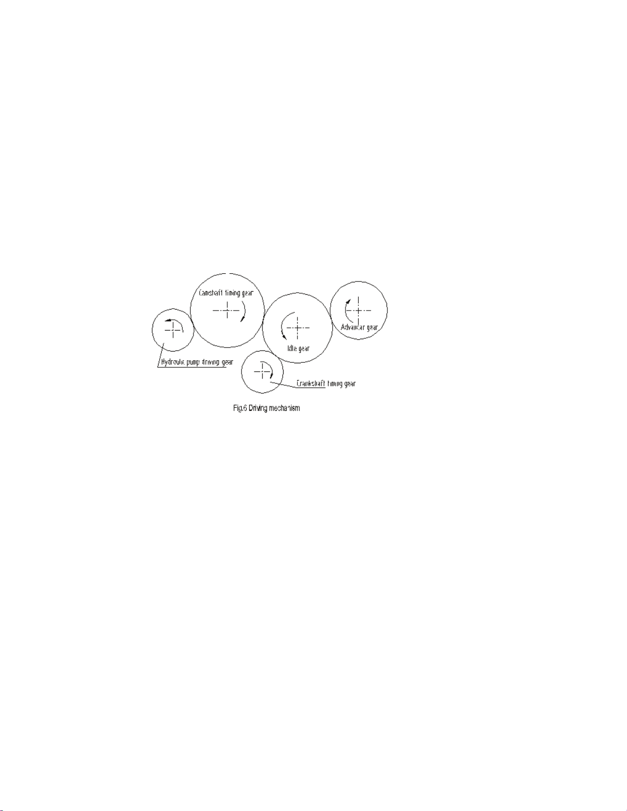
5. DRIVING MECHANISM
The gear driving system of the engine, please refer to Fig.6.
When installing the gears, pay attention to the timing mark on the gear faces to ensure good
phasing and fuel delivery.
After installing the idle gear, check axial clearance. Each gear should turn easily without
clicking.
6 . V A L V E S Y S T E M
V a l v e m ec h a ni s m:
The mechanism is top - mounted valve type. The camshaft is made of No. 45 steel choicely. The
surfaces of camshaft and gear are high frequency quenched. There is a thrust plate in front of first
shaft journal. Axial clearance of camshaft is 0.07-0.245 mm.
Valve tappet is made of chilled casting iron. There is a position deviation between tappets
center and cam center, so that the tappet could continuously turn for smooth wearing during
operation to prevent seizing. Push rod is made of steel; one end is bail structure, the other end is of
bowl structure. Rocker arm shaft is fully supported for high rigidity. Rocker arm and shaft are
lubricated by pressed oil from cylinder head.
Valve and valve seat are made of alloy steel and alloy cast iron and lapped to fit. To check its
fitting, pour kerosene into air port and wait for 2 minutes, no leakage is allowed. Air leakage of
the valve may affect engine technical performance or even burn to damage valve and seat. So
leakage check should be carried out according to technical requirement when in operation. Lap it
when necessary.
A chamfer is designed on valve guide to prevent oil flowing back into cylinder liner and
burning.

Valve clearance adjustment:
Valve clearance shall affect engine performance. It should be checked and adjusted according
to technical maintaining stipulation. The intake valve cooling clearance is of 0.20-0.25mm,the
exhaust valve cooling clearance is of 0.25-0.30mm. The adjusting procedure as following:
Make the first cylinder piston stop at T.D.C. position when the "0" mark on crankshaft pulley
is aligned with the arrow mark on gear case cover, then check and adjust valve clearance of the
first valve (count from the engine front end) by inserting a valve clearance gauge. Turn the
crankshaft 180° subject to the cylinder working order 1 –3 - 2 to adjust every valve clearance.
7 . F UE L S U P P LY S Y S T E M
The fuel supply system consists of delivery pump, injection pump, speed adjustor, fuel filter,
injector, delivery pipe and injection pipe etc. Fuel is delivered to fuel filter from fuel tank by
delivery pump where the fuel is filtered and transferred to injection pump by a high pressure and
atomized, then injected into chamber through injection pipe.
1) The fuel delivery pump is of piston type and assembled on the side of injection pump.
When in normal operation it is driven by the eccentric camshaft gear of' injection pump. Air inside
the system can be discharged by manual pump when necessary after the engine stopped.
2) Fuel filter cartridge is made of paper, which should be mounted correctly to ensure
completely sealing. To keep fuel clean, replace and clean the cartridge as instruction, otherwise
some elements might be choked or worn out to cause trouble or shorten service life.
3) The injection pump is BQ pump or IW pump, and the plunger diameter of injection pump is
6 or 6.5mm for swirl type engine. Lubrication oil is filled into injection pump from right upper
side until oil drop out from side pipe for complete lubrication. Oil refilling should be carried out
periodically.
I nj e ct i o n p u m p d i s a s s e mb l i ng :
Try not to turn the crankshaft after the pump is disassembled so that to ensure the fuel supplies
timing. Otherwise the marks on idle gear and pump gear should be aligned again by turning tile
crankshaft.
A dj u s t f ue l s u p p ly t i m i ng :
To adjust the angle, firstly discharge air in fuel system, crank the crankshaft to let injection
pump fill fuel. Dismounting injection pipe on first cylinder. Blow off the air in the hole of delivery
valve seat connector, then crank the crankshaft slowly and inspect the fuel level in delivery valve
seat connector, stop cranking immediately when fuel level waves. Check the mark on crankshaft
belt pulley to see whether the advance angle is in comply with the above mentioned specification.
Larger or smaller advance angle can be adjusted by loosening three bolts on pump connecting
plate. If the angle is larger, turn the gear seat counter clockwise a proper angle, If tile angle is
smaller, turn it clockwise for a proper angle, then tighten three bolts and check the angle again.
Adjust injection pump:
Injection pump was already adjusted, checked and lead sealed before ex--works. If
readjustment is necessary, it should be made on special testing machine at repairing workshop.
Injection pipe: inner diameter x outside diameter x length=¶l.5׶6×283mm
Injector:
Open pressure of injector and injector nozzle of every model engine refers to operation manual
page 4 and page 2.
Higher or lower injection pressure shall affect normal injection. When the part is damaged,

the engine shall exhaust black smoke, lower power and speed, raise exhaust temperature or knock
the cylinder. To check the trouble injector, loosen injection pipes one by one, stop injection, and
inspect the color of exhaust smoke. Only the trouble injector stop injection can make the engine
no smoke, crank the crankshaft slowly to check injection sound of each injector, the trouble
injector shall be no sound injection.
I nj e ct o r a d j us t me nt :
Set injector on testing machine; slowly increase pressure to pressure required in main
technical specification table. Check to ensure no fuel drops or leakage, otherwise clean or lap the
nozzle and try again.
Then check atomization at a speed of one injection per second. Atomized injection should be
smooth and fog shape without split, drops, uneven or partial injection but with obvious and
melodious sound when fuel supply is cut off. Generally speaking, an abnormal injection is caused
by unsmooth movement of plunger and barrel. While fuel drops in injection hole is caused by
damaged sealing surface, and uneven injection is caused by heat deflection due to carbon deposit
on head.
Injector dismounting:
When dismounting injector, firstly clean outside surface. Clamp it on bench vice with nozzle
toward upside. Note that the vice mouth should be covered with copper plates. Screw out the
tightening nut, pull out plunger and barrel and put in clean diesel. Turn the injector upside down
and clamp again. Screw out pressure adjusting screw and nut, then take out pressure adjusting
spring and push rod. Clean the plunger and barrel when they are seized or effect poor atomization.
Sink it in diesel for a while when seized, clamp it with cloth covered clipper and lightly turn out
the plunger. To clean plunger and barrel, scrap with wooden sheet dip in gasoline or diesel, metal
sheet is strictly prohibited. If plunger can't move smoothly in barrel, lap it with clean diesel, then
clean to remove all dirty and metal chips.
Speed adjustor:
Speed adjustor is well adjusted and lead sealed when ex-works. Don't adjust it unless necessary.
Adjust speed controller only on pump testing bench to prevent damaging.
8 . L U BR I C AT I ON S Y S TE M
Lubrication system which effect pressure and splash lubrication consists of oil pump, oil filter
and oil channel.
Oil pump is of rotor type and is driven by camshaft gear. The gear shaft and camshaft gear are
lubricated by splashed oil. Oil filter is of paper cartridge type, which should have a good sealing.
While installing the cartridge, care must be taken to prevent leakage or short-way. The system
working pressure is 200-400kpa.
To ensure a longer service life, maintain the lubrication system completely and in time.
9 . C O OL I NG S Y S T E M
Cooling system is of closed, forced water-cooled, which consists of water pump, thermostat, fan,
connecting pipe and radiator etc.
The cooling water in radiator is pumped into cylinder block water cavity, then to cylinder head.
Some water directly flows up to cylinder head and accumulated near thermostat. Some water holes

in cylinder block and head are very small, so care must be taken not to block them especially those
holes between cylinder bores and the triangle area where injection nozzle located to prevent
trouble caused by overheating. Water pump is centrifugal type. If there is trouble in water seal,
water may leak out from overflowing hole, repair it in time. Alter long time operation, some
deposit shall be left in cooling system which can be removed by the following procedure:
Pour the mixture of 700-800g NaOH and 150g kerosene into water cooling system. Run the
engine for 5-10 minutes, then stop for 10 - 12 hours. Restart the engine for 10 –15 minutes, drain
out the mixture and clean cooling system with clear water.
1 0 . E L E CT RI C S Y S T E M
Electric system consists of generator, starting motor, regulator, accumulator, oil pressure
sensor, glow plug and connecting wire etc. Engine normal voltage is 12v.
The negative pole of accumulator and generator should be earthed; positive and negative pole
can't be short circuit to prevent damage.

CHAPTER V ENGINE TROUBLES AND REMEDY
A: ENGINE CAN NOT BE STARTED
Trouble Cause
Remedy
1. Fuel System
1) No fuel in fuel
tank or fuel cock not opens.
2) Air in fuel system
3) Fuel pipes or fuel filter blocked.
4) Poor atomization
5) Lever not return to max.fuel supply position.
1) Fill in fuel or open fuel cock.
2) Discharge air by manual delivery pump.
Check each connect
ion for leakage.
3) Clean pipes and filter cartridge or replace cartridge.
4) Clean nozzle; Adjust injection pressure.
5) Pull the speed adjustor lever with force when starting
to force the lever to max. fuel supply position.
2. Electrical System
l) Impro
per circuit contact
2) Lower voltage of accumulator
1) Tighten the circuit connecting screw.
2) Charge the accumulator.
3. High oil viscosity to lower the engine starting
speed.
3. Cranking the crankshaft for several turns with cranking
handle, or fill in preheated oil.
4. Ambient temperature too low.
4. Fill in hot water to pre- heat starting
5. Lower Compression Pressure in cylinder.
1) Cylinder liner, piston and piston rings worn out.
2) Valve and valve seat fitting not good.
3) No valve clearance.
4) Valve stem blocked in valve guide.
5) Air leakage from cylinder head gasket.
6) Air leakage from injector seat.
7) Valve timing incorrect.
1) Replace new parts.
2) Lap valves.
3) Adjust clearance according to technical requirement.
4) Clean it in kero
sene or diesel.
5) Check cylinder head nuts torque. check whether the
gasket is broken .
6) Check nuts and packing for tightness and damage
7) Check and adjust.
6. Fuel supply advance angle not correct.
6. Check and adjust it.
B: ENGINE POWER DECLINE
Trouble Cause,
Remedy
1. Air filter or intake pipe blocked
1. Clean it.
2. Exhaust pipe blocked
2. Clean it.

3. Insufficient fuel supply.
1) Delivery pipe & fuel filter blocked.
2) Nozzle tip worn out.
1) Clean it.
2) Replace nozzle tip or injector.
4. Water in fuel
4. Replace fuel.
5. Incorrect fuel supply advance angle.
5. Adjust
6. Too much carbon deposit in chamber.
6. Disassemble cylinder head and remove carbon
deposit.
C: ENGINE STOP SUDDENLY
Trouble Cause Remedy
1. No fuel supply.
1) No fu
el in tank.
2) Air in fuel system
3) Fuel filter blocked
4) Water in fuel.
1) Fill in fuel.
2) Discharge air.
3) Clean it.
4) Replace fuel.
2. Piston blocked
2. Replace it.
3. Air filter blocked.
3. Replace filter cartridge.
D: ENGINE RUNNING WITH KNOCKING SOUND.
Trouble Cause
Remedy
1. Fuel supply too early or too late.
1. Readjust fuel supply advance angle.
2. Valve clearance to big
2. Readjust valve clearance.
3. Too big clearance between piston and cylinder liner.
3. Check
and replace piston or
cylinder liner when necessary.
4. Too big clearance between piston pin and connecting
rod bushing, having beating sound.
4. Check and replace connecting rod bushing when
necessary.
5. Too big clearance of main bearing or connecting rod
bearing, having ramming sound.
5. Check and replace connecting rod bearing or main
bearing when necessary
6. Valve knock with piston top.
6. Adjust timing phase.
E: OIL PRESSURE TOO LOW.
Trouble Cause
Remedy
1.Insufficient oil in sump.
1. Fill
in oil.
2. Oil pipes or oil filter cartridge blocked.
2. Clean and replace when necessary.
3. Oil viscosity too low.
3. Replace oil according to technical requirement.
4. Cylinder head gasket, water pump packing or gear
case cover packing damaged to induce water into oil.
4. Replace damaged gasket ,packing and oil
5. Suction fuel pipe connector leakage
5. Check and repair it
6. Oil pump rotors seriously worn out.
6. Replace rotors and adjust clearance.

7. Too large clearance between main bearing and
connecting rod bearing.
7. Check and replace when necessary.
8. Improper adjustment of pressure adjusting valve on
oil filter.
8. Readjust it
9. Oil pressure gauge damaged
9. Replace it
10. Wrong assembling of oil filter seat packing
10. Reassemble it
F: ENGINE OVER HEAT
Trouble Cause Remedy
1. Cooling system out of order
1) No water in radiator
2) Too much deposit in water passage
3) Fan and water pump belt too loose.
4) Space between radiator and fan is not suitable.
5) Water inlet and outlet
pipe deformed or blocked
1) Fill in water
2) Add alkaline solution (750g alkaline in I0 L water),
operating 4
-
8 hours and discharged, then use clean
water to clean the passage.
3) Adjust the tension of belts or change belt when
necessary.
4) Adjust it.
5)Replace it.
2. Fuel injection delayed or nozzle leaks fuel.
2.Adjust the fuel delivery advance angle or repair
nozzle.
3. Oil insufficient causes oil pressure too low and
temperature too high.
3. Add oil.
4. Valve phasing is incorrect.
4. Adjust it.
5. Thermostat out of order.
5. Replace it.
6. Engine running overload for a long period.
6. Reduce load.
G: ENGINE EXHAUST ABNORMAL SMOKE.
Trouble Cause
Remedy
1. Exhaust blue smoke (oil in cylinder)
1) Piston rings, cylinder liner worn out or piston
rings jammed.
2) Intake or exhaust valve guide hole worn out.
3) Too much oil in oil sump.
1) Repair or replace it.
2) Replace it.
3) Drain out some oil.
2. Exhaust white smoke (Engine in cold condition with bad fuel
atomization in low load condition. )
1) Fuel injection pump delivery too much fuel.
2) With bad fuel atomization, fuel pressure is too low
3) Fuel delivery too late
4) Cylinder compressing pressure is low.
5) Fuel with water
1) Adjust fuel delivery.
2) Inspect injection pressure or replace fuel
injector when necessary.
3) Adjust fuel advance angle
4) Refer to a
-5
5) Replace fuel.
Table of contents
Popular Engine manuals by other brands


Allen-Bradley
Allen-Bradley Rockwell Automation RDD Series installation instructions

Lombardini
Lombardini LGA 226 Use & maintenance

DANA
DANA BREVINI T Series Installation and maintenance manual

Predator Engines
Predator Engines 301cc Owner's manual & safety instructions

Montanari
Montanari MGV25 Series Use and maintenance

Nice
Nice NEO S Installation and use instructions and warnings