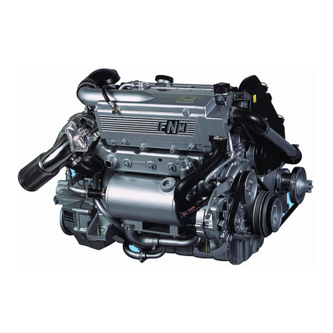
FNM HPE Series User manual

Installation Manual
Marine Diesel Engines HPE Series
HPE 40S/80/80SD/110/135
HPE 110JD/135JD
HPE/P 40/150/170/190/205
HPE 150JD/170JD/190JD/205JD
HPE/P 100/225/250/250H
HPE 225JD/250JD
HPE/P 300
HPE/P 300JD
HPEL 45/80/65/90


i
Table of contents
1General information and warnings ............................. 1
1.1 General information ............................................... 1
1.2 Warnings about this manual .................................. 1
1.3 Warranty information.............................................. 1
2Engine technical data................................................... 3
2.1 Product identification.............................................. 3
2.2 Documentation attached........................................ 3
2.3 Leisure engine technical data ................................ 4
2.4 Work engines technical data:................................. 4
2.5 Power, Torque and Operating cycles of Diesel
Marine Engines FNM® series HPE..................................... 4
2.6 Power-rating for commercial use ........................... 5
3Engine installation........................................................ 7
3.1 Engine and transmission combinations ................. 7
3.2 Engine Disassembling and Handling ..................... 7
3.3 Engine elements .................................................... 8
3.4 Principles of preparation of the engine
compartment..................................................................... 12
3.5 Ventilation............................................................ 12
3.6 Installation angles ................................................ 13
4Engine alignment........................................................ 14
4.1 Anti-vibration mounts ........................................... 14
4.2 Engines with Mercruiser Bravo® stern drive........ 15
4.3 Engines with inverter............................................ 18
4.4 Engines with Twindisc Seaprop® sail drive ......... 19
4.5 Engines with Alamarin® water-jet propulsion unit 19
4.6 Engines with Volvo® stern drive prearrangement 20
5Services connection to the engine compartment.... 21
5.1 Services connection points .................................. 21
5.2 Fuel circuit ........................................................... 21
5.3 Sea water circuit .................................................. 22
5.4 Exhaust system ................................................... 24
5.5 Hydraulic fluid circuit (if present).......................... 25
5.6 Throttle................................................................. 26
5.7 Propeller selection and torque engines installation
drawings ........................................................................... 28
6Wiring installation ...................................................... 29
6.1 Electrical system and system specifications ........ 29
6.2 Battery and power supply .................................... 29
6.3 Control Unit.......................................................... 30
6.4 Fuses and relays ................................................. 31
6.5 Control panel ....................................................... 31
6.6 Basic electrical connections................................. 34
6.7 Trim Circuit (if present) ........................................ 35
6.8 Fuel level in the tank sensor (if present) .............. 36
6.9 Calibration of trim and fuel level signals on the
CANBUS instrument ......................................................... 37
6.10 Transmission oil level alarm (if present) .............. 37
6.11 Rudder angle sensor (if present) ......................... 38
6.12 GPS sensor (if present) ....................................... 38
6.13 Other sensors and auxiliary cables...................... 38
6.14 Emergency stop switch (if present)...................... 38
6.15 Electronic throttles electrical connection.............. 39
7First power on and sea trial....................................... 40
7.1 Preliminary checks............................................... 40
7.2 Sea trial and Installation Form filling in ................ 40
8Accessories ................................................................ 42
8.1 Heating Kit (Boiler)............................................... 42
8.2 Accessories Additional Pulley (PTO) ................... 44
8.3 Additional Alternator ............................................ 45
8.4 Insulated Pole Kit................................................. 45
8.5 Maretron® NMEA2000 Control Unit..................... 45

FNM® Series HPE –Installation Manual –1
1General information and warnings
1.1 General information
Welcome to the family of users and installers of Diesel Marine
Engines branded Fratelli Negri Motori® (hereinafter FNM®).
This manual will help you to properly install the engine inside
the boat.
Carefully read the entire manual BEFORE
starting the installation operations on the engine.
Over the years FNM® brought important innovations in the
world of marine diesel engines. The FNM® engines are at the
forefront for electronic control, performance, lightness and
flexibility. The innovations that FNM® brought in the marine
world require specific knowledge for installation, use and
maintenance of the HPE marine diesel engine .
This manual will help in the installation of all the engines of the
HPE family, whether they are equipped with straight, angled or
V inverter, stern drive, sail drive and water-jet propulsion unit.
This installation manual was written and published by
Costruzioni Motori Diesel SpA (Hereinafter CMD) owner of the
trademark FNM®, to assist buyers involved in the application
and installation of the products described.
It is assumed that the installers are thoroughly familiar with the
application of marine products and with the installation of
these products, or similar products made and sold by CMD.
CMD does not have the possibility to know each installation
case by case and suggests installers the most appropriate
procedures to be followed from time to time, in addition to the
possible hazards and/or results of each singular application or
installation. This manual is a general guideline for the engine
installation and contains principles that must be generally
followed. Operators who install the FNM® engine without
following the instructions given here are responsible for the
consequences of their work. Failure to follow the directions
included in this manual will void the warranty conditions.
It is the responsibility of the boat manufacturer to select the
appropriate engine/inverter/transom/stern drive assembly
(including the right transmission speed and the right propeller)
for a given ship. Proper selection requires specific knowledge
of the boat (weight, hull length, use and operation, desired
cruising speed, etc.) which only the boat manufacturer knows.
CMD recommends that any connection between the hull and
the engine of different power must be tested in water before
delivering the product to the customer. It is necessary to check
along with other things, that the performance of the boat is as
desired, and that the engine works at an acceptable speed.
Do not hesitate to contact CMD for assistance if you are
having specific problems related to the application or
installation.
All information, images and specifications in this manual are
the latest product information available at the time of
publication. Upon request, the changes in this manual will be
sent to all installers that require it.
1.2 Warnings about this manual
The information contained herein cannot avoid the dangers
arising from incorrect installation of the engine, but are an
effective preventive measure, combined with a dose of
common sense in every action that you make.
Here are some symbols that indicate potential danger,
indicated depending on the severity:
Serious danger of death or injury to persons.
Low hazard of injury to persons or serious damage
to the engine and other objects.
Information to follow to avoid incurring in damage to
the engine and in the serious dangers.
Information to be followed to prevent damage to
the environment
1.3 Warranty information
In order to obtain the guarantee acknowledgement by CMD
S.p.A. for marine diesel engines FNM® it is mandatory to fill in
the ''Installation Form" and transmit it to After Sale
Management service of CMD by mail in the original copy. The
shipping address is:
After Sale Management
C.M.D. Costruzioni Motori Diesel S.p.A.
Zona Industriale Valle di Vitalba
85020 Atella (PZ) - ITALY
If the installation form is not sent, it will void the
engine warranty.

2 –FNM® Series HPE –Installation Manual
The installation form (CMD Model 1408.02, a copy attached at
the end of this manual) is positioned together with the
documentation accompanying the engine. A copy of the form
can also be obtained by contacting the After-Sales
Management at the above address or at the contacts below:
After Sale Management
Tel. +39 0972 715757
Fax. +39 0972 715696
Email: service.fnm@cmdengine.com
Web: www.fnm-marine.com

FNM® Series HPE –Installation Manual –3
2Engine technical data
2.1 Product identification
HPE series marine engines are divided into classes depending
on the family and application to which they are intended:
Model (or Engine Type)
Family
Application
HPE 40S/80/80SD/110
HPE 110JD/135JD
1.3HPE
Yachting
HPE/P 40/150/170/190/205
HPE 150JD/170JD/190JD/205JD
1.9HPE
Yachting
HPE/P 100/225/250/250H
HPE 225JD/250JD
2.4HPE
Yachting
HPE/P 300
HPE 300JD
3.0HPE
Yachting
HPEL 45/80
1.3HPE
Work
HPEL 65/90
1.9HPE
Work
2.1.1 ID label
The ID label is applied on the engine and on the control unit
(or ECU Box), in the position indicated in the table below (see
also paragraph 3.3 - Engine elements on page 8):
Engine
Label position on the engine
1.3HPE
1.9HPE
On the engine crankcase.
2.4HPE
On top of the engine, attached to the intercooler housing.
3.0HPE
On the cooled exhaust manifold on the right side of the
engine.
The data that are found on the identification label are given
below as an example:
- Engine Type
- Engine Family according to RCD (CE).
- Engine Serial No.
- Year of manufacture
- Test speed (Rpm)
- Power in kW (kW)
- Horsepower (HP)
2.1.2 Engine serial No.
The engine serial number is also printed on the engine block.
The location is shown in the table below (see also paragraph
1.6 - Main components of the engine FNM HPE Series ® - on
page 16):
Engine
Engine serial number position
1.3HPE
1.9HPE
2.4HPE
On the right side of the crankcase, bell housing connection,
or on the front side of the crankcase, above the bell
housing.
3.0HPE
On the crankcase, front side, above the bell housing.
The serial number of the engine is constituted as follows:
Position
1
2
3
4
5
6
7
Serial
number
4
7
1
1
0
X
X
Positions 1-2:
Identification code of the model.
Positions 3-4:
Last two figures of the engine year of
production
Positions 5-7:
Progressive
Besides the engine also the transmission, transom and stern
drive have their own serial number, indicated on each of them
by the respective manufacturers.
Communicate to CMD the serial number of each element of
the propulsion system whenever you require any maintenance.
2.1.3 EPA/IMO Label
The engine can be provided with a label which indicates the
presence of EPA certification and/or IMO MARPOL Annex IV
pre-certification.
The label is usually affixed near the identification label and
reports the EPA/IMO family number. If the engine is equipped
with IMO MARPOL Annex IV (NOx), pre-certification, the
information regarding the pre-certification is contained in the
certificate attached to the engine.
2.2 Documentation attached
The HPE marine diesel engines are accompanied by the
following documentation:
- Use and Maintenance manual
- Installation Manual (this document)
- Installation Form
Costruzioni Motori Diesel SpA
Z.I. Valle di Vitalba
85020 Atella (PZ) Italy
Engine Type: HPE110
Engine Family: 13T4L550
Serial No.: 47110XX Year: 2011
Rpm: 4400 kW: 80.88 HP:110

4 –FNM® Series HPE –Installation Manual
- Transmission manual (if any)
- Quick Reference Guide for the CANBUS instrument use
2.3 Leisure engine technical data
1.3HPE
1.9HPE
2.4HPE
3.0HPE
Cylinders
4
4
5
4
Displacement
[cm3]
1248
1910
2387
2988
Bore [mm]
69.6
82.0
82.0
95.8
Stroke[mm]
82.0
90.4
90.4
104.0
Engine type
Four stroke diesel engine -
Compression
ratio
17,6:1
18:1
Injection Type
Direct Common Rail Injection
Boosting
Turbine with variable
geometry
Turbine
with cooled
turbocarter
Turbine with
cooled body
Timing system
16-Valve DOHC
20-Valve
DOHC
16-Valve
DOHC
Firing order
1-3-4-2
1-2-4-5-3
1-3-4-2
Alternator
75A 12V
105A 12V
140A 12V
110A 12V
Engine oil
capacity (without
filter) [l]
3.2
4.0
4.5
7.5
Thermostatic
valve
65°C ± 1.5°C
(88°C for 1.3HPE MK3)
65°C±1,5°C
80°C
±1,5°C
Cooling capacity
[l]
7.5
7.5
8.5
14.0
Sea water pump
flow [l/min]
90 (24,0
gal/min)
100 (26,6 gal/min)
Engine starter
1.3 kW
12V
1.8 kW 12V
2.6 kW 12V
Wet weight
(excluding
transmission)
[kg]
188
240
295
335
Direction of
rotation of the
flywheel
Counterclockwise (bell housing side)
For all rating data (torque and power), refer to the table in
paragraph 2.5 on page 4.
2.4 Work engines technical data:
HPEL 45
HPEL 80
HPEL 65/90
Cylinders
4
4
Displacement [cm3]
1248
1910
Bore [mm]
69.6
82.0
Stroke[mm]
82.0
90.4
Engine type
Four stroke diesel engine -
Compression ratio
17,6:1
18:1
Injection Type
Direct Common Rail Injection
Boosting
aspirated
Turbine with variable geometry
Timing system
16-Valve DOHC
Firing order
1-3-4-2
Alternator
75A 12V
105A 12V
Engine oil capacity
(without filter) [l]
3.2
4.0
Thermostatic valve
65°C ± 1.5°C
Cooling capacity [l]
7.5
7.5
Sea water pump flow
[l/min]
90 (24,0 gal/min)
100 (26,6
gal/min)
Engine starter
1.3 kW 12V
1.8 kW 12V
Wet weight (excluding
transmission) [kg]
158
188
240
Direction of rotation of
the flywheel
Counterclockwise (bell housing side)
For all rating data (torque and power), refer to the table in
paragraph 2.5 on page 4.
2.5 Power, Torque and Operating cycles of
Diesel Marine Engines FNM® series HPE
FNM® diesel marine engines are designed to operate within
the range of minimum and maximum speeds shown in the
table.
Power and maximum torque are achieved at the speeds
indicated:

FNM® Series HPE –Installation Manual –5
Model
Minimum [rpm]
Maximum no-load
speed [rpm]
Maximum Power
Maximum
Torque
[HP]
[kW]
[rpm]
[Nm]
[rpm]
HPE
80/80SD
850
4700-
5300
75
55.1
3800
157
2200
HPE
110/110JD
850
4700-
5300
110
80.8
4000-
4400
230
2600
HPE
135/135JD
850
4700-
5300
129
95
4000-
4400
260
2600
HPE/P 40
850
-
40
29.4
3200
91.4
2600
HPE/P
150/150JD
850
-
150
110
4000
311
2500
HPE/P
170/170JD
850
-
170
125
4000
338
2200
HPE/P
190/190JD
850
-
190
139.7
4000
372
2400
HPE/P
225/225JD
-
-
225
165.4
4000
416
2500
HPE/P
250/250JD
800/850
-
250
184
4200
460
2600
HPE/P
250H
850
-
110
80.8
3000
-
-
HPEP/P
300/300JD
800
-
295
217
4000
560
2600
HPEL 45
800-
850
-
45
33
3000
-
-
HPEL 80
800-
850
-
90
66
4000
-
-
HPEL 65
800
-
65
47.8
4000
-
-
HPEL 90
800
-
90
66
4000
-
-
Use at maximum power only for short periods of time.
The damage caused by improper use or lack of
compliance with the range of use in terms of
crankshaft speed, will not be covered by the
guarantee by CMD.
2.6 Power-rating for commercial use
Some units of the range, while having the same set-up of the
above versions can be supplied with calibrations at reduced
power for commercial use.
The power reduction is needed when the engine is used in
harsh conditions or for long continuous periods.
There are four classes and one sub-class of power-rating:
- Class A - Leisure Boats: The use at full load is limited to
10% of the total period of use. The maximum power can
be used for 1 hour every 10 hours of use. Outside of
periods of use at maximum load, the speed must be
reduced by at least 10% compared to that of maximum
power. The cruising speed must be 90% less than the
maximum power speed. Limit of use: 300 hours per year.
- Subclass A1 - Light Commercial Applications for
Special Use: For light boats in commercial applications
for special use. The guarantee conditions may vary
depending on the application, check the warranty terms
with the company representative.
- Class B - Light Commercial Applications: The use at
full load is limited to 12.5% of the total period of use. The
maximum power can be used for 1 hour every 15 hours of
use. Outside of periods of use at maximum load, the
speed must be reduced by at least 10% compared to that
of maximum power. The cruising speed must be 90% less
than the maximum power speed. Limit of use: 800 hours
per year.
- Class C - Medium-Heavy Commercial Applications:
The use at full load is limited to 20% of the total period of
use. The maximum power can be used for 1 hour every 5
hours of use. Outside of periods of use at maximum load,
the speed must be reduced by at least 15% compared to
that of maximum power. The cruising speed must be 90%
less than the maximum power speed. Limit of use: 1200
hours per year.
- Class D - Heavy Commercial Applications: The use at
full load is limited to 60% of the total period of use. The
maximum power can be used for 1 hour every 2 hours of
use. Outside of periods of use at maximum load, the
speed must be reduced by at least 15% compared to that
of maximum power. The cruising speed must be 90% less
than the maximum power speed. Limit of use: 3000 hours
per year.
The limits of use are summarized in the following tables:
Power
Rating
Class
Limit use [h/year]
Use limit at
full load
Use limit at
maximum
power
[%]
[h/year]
[%]
[h/year]
A
300
10
30
10
30
A1
(*)
B
800
12.5
100
7
53
C
1200
20
240
20
240
D
3000
60
1800
50
1500
(*): Check the terms of use with the company representative.

6 –FNM® Series HPE –Installation Manual
Model
Power
Rating Class
Maximum Power
[HP]
[kW]
[rpm]
HPE/P 300
A
295
217
4000
A1
B
250
184
4100
C
180
132.3
4000
D
130
95
4000
HPE/P 250
A
250
184
4200
A1
B
225
165
4200
C
150
110
4200
D
100
73.5
4200
HPE/P 190
A
200
147
4100
A1
B
170
125
4100
C
140
103
4100

FNM® Series HPE –Installation Manual –7
3Engine installation
3.1 Engine and transmission combinations
The transmission system of marine engine changes depending
on the equipment chosen. Different configurations are
available:
- Engines with inverter, indicated by the abbreviation HPE
followed by rated power (in HP). The inverters are
configured:
oin lineshaft (with centre distance or coaxial)
owith angled axis (A)
owith inversion of the axis (V)
- Engines with stern drive, indicated by the abbreviation
HPEP followed by the rated power.
- Engines with sail drive, indicated by the abbreviation HPE
followed by the rated power. The model name can be
followed by the initials SD (Saildrive).
- With water-jet engines, indicated by the abbreviation HPE
followed by rated power. The model name can be
followed by the initials JD (JetDrive).
Work use engines are generically indicated with the
abbreviation HPEL followed by the rated power, regardless of
the transmission to which they are coupled.
The name of uncalibrated engines with power-rating (see
paragraph 2.6 - Power-rating for commercial use on page 5),
can be followed by the letter of the power rating at which the
engine has been calibrated (e.g. HPE 300-B indicates the
rating class B).
3.2 Engine Disassembling and Handling
At moment of receiving an HPE engine please check:
- The integrity of the packaging: the wood box must be
integral; the engine must be fixed on the wood support
and secured to it.
- The metal box sealed watertight containing the electronic
control unit. The set must be intact with no obvious signs
of breakage or tampering.
- The engine wiring and any extension cables must be
integral with no cuts, the Amphenol® connectors
(between control unit and engine wiring) must be integral
and all the pins of the connector must be correctly
deformed.
- The integrity of the instrument panel and the associated
wiring. The panel must be free from cosmetic defects.
- The absence of spots or dripping due to leakage of
liquids.
At the presence of leakage or spots, check the
cause of the leak. The product may contain dripping
caused by the operation on the test bench.
Before shipping all engines are tested at the bench
and packed carefully. FNM® is not responsible for
damages caused by the carrier/transport company.
Figure 1 –Engine lifting
Lift the engine exclusively with chain or lifting ropes of
adequate capacity. Make sure that the chain is sufficiently long
so that it doesn't to lean on lifting hooks with an angle greater
than 10°, as shown in Figure 1. Also make sure that the chain
does not damage the engine parts during lifting.
Do not apply additional weight to the engine
during its lifting! The hooks are designed to
support only the weight of the engine. In the
case of engines fitted with inverter, lift the
assembly also from the hook of the inverter.
Never stand underneath a raised engine with
chain and always check the maximum capacity
of the equipment used (hoist or forklift and
chain).
Make sure that when lifting the engine it always remains
perfectly level horizontally. Some engines requires the use of a
lifting bar (or a spacer) that appropriately distributes the chain
tension.
maximum 10°
CHAIN
HOOK ON THE
ENGINE

8 –FNM® Series HPE –Installation Manual
Figure 2- Lifting bar for engine levelling.
Consult the length of the lifting bar in the following table:
Model
Length of the lifting bar [mm]
1.3HPE
not necessary
1.9HPE
570
2.4HPE
630
3.0HPE
not necessary
Lift on 3 points
See the position of the hooks in paragraph 3.3 - Engine
elements on 8.
In the case of engines with the inverter connected,
remember that the weight of the inverter offsets the
centre of gravity of the engine. Be careful when
lifting the engine.
The case containing the engine must be preserved and reused
in the cases of resending the engine to the manufacturer,
since it is the only packaging able to ensure the integrity of the
engine during transport. For storage of the case, disassemble
the banks folding them on themselves and stack the platform,
sides and lid in a cool, dry place.
3.3 Engine elements
The main components present on HPE marine engines are
listed below.
1. Intercooler (except HPEL45): reduces the temperature of
the compressed air from the compressor that flows into
the engine intake duct using a bundle of finned tubes
crossed by seawater.
2. Expansion tank: contains engine coolant.
3. Oil sump: contains engine lubrication oil.
4. Zinc anodes: prevent the galvanic oxidation of metal
parts.
5. Oil exchanger: reduces the temperature of the engine
lubrication oil.
6. Diesel fuel exchanger: reduces the temperature of the
fuel in the return line to the exchanger.
7. Air filter: retains the impurities in the air intake.
8. Double exchanger (as an alternative to the diesel
exchanger in the presence of fuel and power steering):
reduces the steering oil and diesel temperature.
9. Turbocharger (except HPEL45):compresses the intake
air exploiting the energy of exhaust gases through the use
of a turbine-compressor group.
10. Diesel fuel filter: filters diesel fuel in inlet to the supply
line of the engine. It can be wall-mounted in the engine
compartment.
11. Raiser or discharge elbow: reduces the temperature of
the exhaust gases coming out of the turbine, conveys
fumes towards the exhaust and prevents the return of sea
water into the turbine.
12. Starter: starts the engine.
13. Water/water exchanger: reduces the temperature of
engine coolant through heat exchange with sea water.
14. Low-pressure electric fuel pump: sucks fuel from the
low pressure line and sends it to the high pressure line.
15. Thermostat housing: contains the thermostatic valve of
the cooling circuit.
16. Sea water pump: sucks water from the sea water intake
and pushes it in the cooling circuit.
17. Alternator: generates electric power, the output voltage is
12 Volt.
18. Oil filler cap: useful in filling the engine oil.
19. Lifting eyes: allow the movement of the engine outside
the engine compartment.
20. Engine label position
21. Serial number position on the crankcase
22. Oil drain valve

FNM® Series HPE –Installation Manual –9
Figure 3 –FNM® HPEL 40S/80/80SD/110/110JD and HPEL 80
Figure 4 –FNM® HPE/P 40/150/170/190, HPE 150JD/170JD/190JD and HPEL 65/90
1
2
3
4
5
6
7
9
10
11
12
13
14
15
16
17
18
19
19
20
21
1
2
3
10
7
9
11
12
13
14
15
16
17
18
19
19
8
21
20
22

10 –FNM® Series HPE –Installation Manual
Figure 5 –FNM® HPE/P 100/225/250/250H and HPE 225JD/250JD
Figure 6 –FNM® HPE/P 300
1
2
3
10
7
9
11
12
13
14
15
16
17
18
19
19
8
20
21
22
1
2
3
10
7
9
11
12
13
14
15
16
17
18
19
19
8
13
19
20
21
22

FNM® Series HPE –Installation Manual –11
Figure 7 –FNM® HPEL 45
2
3
5
7
11
12
13
14
15
16
17
18
19
19
20
21

12 –FNM® Series HPE –Installation Manual
3.4 Principles of preparation of the engine
compartment
The engine compartment houses the propulsive units and has
several functions: it allows to keep the engine cool and dry,
still on the longitudinal members, ensuring ventilation and the
air flow required for its operation. Finally it contains all the
accessories and auxiliary parts necessary for the operation of
the entire propulsion system.
It is necessary to pay attention to the design and construction
of the engine compartment. The walls must be built so that
rainwater and splashes of sea water do not go directly against
the engine or suction devices.
3.4.1 Longitudinal members
The longitudinal members must be straight and oriented in the
direction of the hull length. They must be quite stiff and firm to
hold the engine and keep its alignment over time.
The distance provided for each engine (indicated by the letter
din the image of Figure 8) between the centre of the right
longitudinal member and of the left longitudinal member is
shown in the following table:
Engine
Distance dbetween the longitudinal members centres
[mm]
1.3HPE
440
1.9HPE
from 560 to 640
2.4HPE
from 560 to 650
3.0HPE
570
Figure 8 –Longitudinal members
The side members must completely contain the basis of the
anti-vibration mountings and have margin to be able to move
in the future, in case it is necessary to realign the engine.
Use screws of adequate size to secure the engine to the
supports. All the forces exerted by water on the hull of the boat
are transmitted to the engine through the side members, and
therefore to the fixing screws. Also make sure there is enough
space on the bottom of the boat between the engine and the
hull.
3.5 Ventilation
The requirements for engine ventilation vary considerably
among the different ship designs. The manufacturer of the
boat is responsible for their construction and the correct
application of the principles of ventilation, in accordance with
regulations.
The ventilation of the engine compartment has multiple
functions. It must supply the engine with air for combustion
and maintain the temperature inside low. The purpose is to
ensure a correct air flow rate necessary for the proper
operation of the engine and to reduce the risk of moisture and
condensation.
3.5.1 Reduction of condensation
Figure 9 - Engine compartment ventilation diagrams
In the image of Figure 9, the fan represented is appropriate for
adequate ventilation of the compartment in order to reduce the
presence of moisture and condensation. It should be applied
also in cases where the shape of the engine compartment
does not favour a correct air passage around the entire
engine.
3.5.2 Ventilation openings
In the engine compartment must always enter air at the lowest
temperature possible; warm air must be discharged upwards.
The vents must not allow access to rain water or to splashes
of seawater during navigation.
d
Better
Good
Acceptable
Worst
engine
engine
engine
engine

FNM® Series HPE –Installation Manual –13
The size of the ventilation openings must be
multiplied by the number of engines installed.
The combustion air flow rate (for single engine) is shown in the
following table:
Engine
Intake air flow rate
[m3/min]
[ft3/min]
1.3HPE
8
282
1.9/2.4HPE
10
353
3.0HPE
12.5
424
The best temperature of operation of the engine is
between 30 and 40°C. This temperature must be checked
after the installation, near the air inlet filter to the engine. For
this purpose, the minimum diameter of the ventilation openings
is indicated in the following table:
Engine
Dimension of the ventilation openings
Intake [cm2]
Exhaust [cm2]
1.3HPE
184 (28 in2)
80 (12 in2)
1.9/2.4HPE
230 (35 in2)
100 (16 in2)
3.0HPE
285 (45 in2)
125 (20 in2)
If it is not possible to reach an operating temperature within
the indicated range, or to improve the air inflow to the engine,
it is appropriate to increase the size of the ventilation
apertures.
Even with the increase in the size of the ventilation openings it
is not possible to return within the indicated range because of
weather conditions or the shape of the engine compartment, it
is necessary to check the difference between the outside
temperature and the engine compartment: this should never
be above 25°C.
Intake temperatures above 40°C can damage the
engine.
Failure to follow the instructions regarding the
dimensions of the openings and the operating
temperature compromises the engine reliability and
will void the warranty.
3.6 Installation angles
Refer to the table below for the maximum installation angles
and use of the engine.
Engine
Maximum
longitudinal angle
of continuous
operation (static
+
dynamic)[degrees
/360]
Maximum
transverse angle
of continuous
operation (static
+
dynamic)[degrees
/360]
Longitudin
al for
checking
the oil
level with
standard
dipstick
[degrees/3
60]
1.3HPE
± 20
± 25
0 ÷ +6
1.9/2.4/3.0
HPE
± 10
± 20
0 ÷ +6
Use the engine speed out of the ranges allowed may
constitute a serious failure of the production unit
because of the lack of oil in the pump and can lead
to engine damage.
Always check the oil level when the engine is in a
horizontal position, or within the limit indicated in the
table above.

14 –FNM® Series HPE –Installation Manual
4Engine alignment
The engine alignment with the transmission must be carried
out carefully. Depending on the type of transmission to which
the engine is coupled, it is necessary to follow different
alignment methods.
The installer of the engine in the boat is responsible for the
alignment of the engine to the transmission system. Once
finished the alignment, these must always be checked again
after the first set in motion and before delivery of the boat to
the customer.
An improper alignment leads to vibrations of the
propulsion unit that may damage parts of the engine
and transmission, as well as to affect their operation.
One of the purposes of a correct alignment of the engine it is
to eliminate all the vibrations of the propulsion system and
thereby reducing the mechanical stresses and noise.
The failure of parts of the engine and
transmission due to a bad alignment may cause
danger to the boat user.
All transmission parts with parts in motion must
be suitably protected to prevent the user's
contact with running engine.
4.1 Anti-vibration mounts
Regardless of whether it is equipped with stern drive, inverter,
water-jet propulsion unit or sail drive, the engine must rest on
some anti-vibration mounts installed directly on the side
members.
The anti-vibration mounts are made as in Figure 10:
Figure 10 - Anti-vibration mounts
It is always better to use stud bolts rather than screws with
hexagon head because it ensures a greater fixing duration: if
you need to loosen the support in fact, the stud bolt remains
stationary in the longitudinal member. Prevent that the screw
is removed every time ensures durability of the bond between
screw and nut.
The orientation and the number of mounts necessary to fix the
engine are indicated in the following table:
Transmission
Orientation
Supports
Distribution
side
Flywheel
side
On-line inverter
stern flywheel
2
2
Angle inverter
stern flywheel
2
2
V inverter (V-drive)
bow flywheel
2
2
Water-jet propulsion
unit
stern flywheel
2
2
Stern drive
Mercruiser® (Z-
drive)
stern flywheel
2
-
Sail drive
stern flywheel
2
-
Stern drive Volvo®
(Z-drive)
stern flywheel
2
-
In some cases (stern drive engine) it is not necessary the use
of supports on the flywheel side because the engine is
connected integrally to the transmission which acts as a
support for the engine.
The nuts for supporting and clamping the engine on the
threaded pin of the anti-vibration mount must be carried out
with a torque wrench at a torque of 150 Nm (110 lb-ft).
The selection of the correct hardness and type of anti-
vibration mounts is made by the installer and it should be
made taking into account the type of boat and the stresses
that the hull will transmit to the propulsive assembly, in
addition to the weight and arrangement of the latter inside of
the boat.
The choice of mounts of incorrect size can cause
engine damage and preclude its operation.
Hex Head
Screw
(alternative)
Anti-
vibration
mount
Stud bolt
(preferable)
Engine
support nut
Engine tightening nut

FNM® Series HPE –Installation Manual –15
4.2 Engines with Mercruiser Bravo® stern drive
For the installation of the engine supplied with Mercruiser
Bravo® I, II or III, stern drive, carefully follow the
manufacturer's installation manual (Cummings Mercruiser
Diesel®) supplied with the engine. Please also consider the
following information.
Carefully follow the instructions contained in the
stern drive installation manuals of the manufacturer,
or this may invalidate the warranty.
The transom positioning is not covered by this manual, and is
available on the stern drive manufacturer's manual. The hull
and engine compartment of the boat must be designed so as
to allow the correct positioning of the transom - and
consequently the engine - inside of them, without causing
problems to the circuits connection (such as e.g. exhaust for a
too high waterline related to the engine position).
4.2.1 Stern drive transom preparation
After positioning the transom and installing the piston to
control the rudder and the rear exhaust, as described in the
installation manual of the stern drive Mercruiser Bravo®,
before installing the rest of the stern drive, it is necessary to
position and install the engine. Follow the steps below:
1. Make sure that the engine bell contains the rubber bushes
needed to couple with the transom supports. The
bushings are shown in the image of Figure 11 with the
letter a.
Figure 11 - Engine bell for Mercruiser Bravo® stern drive
2. Always use fibre washers (indicated by the letter b in
Figure 11) between the engine bell and transom.
4.2.2 Engine positioning with Bravo Mercuiser stern
drive
After preparing the transom, follow these steps:
3. Lift the engine and keep it suspended above the side
members. Make sure the engine is level when suspended.
For the criteria for handling the engine, refer to the paragraph
3.2 - Engine Disassembling and Handling on page 7.
4. Lower the engine in the hull position making it go down
slowly.
5. Install flexible mountings at the front of the engine (see
paragraph 4.1 –Anti-vibration mounts on page 14). Do
not tighten the nuts of the supports , or the supports to the
side members.
The supports tightening must be performed only at
the end of this procedure.
6. Align the rear of the engine with the transom inner plate.
At the same time align the upper exhaust pipe of the
engine with the lower exhaust of the transom.
A wrong coupling between the bell supports and the
transom cause inaccurate alignment, which may
lead to irreparable damage of the engine.
7. Insert and tighten both bolts as shown in Figure 12. Do
not tighten the bolts, but leave a clearance.
Figure 12 - Bolts tightening between the engine and transom
supports. a) engine support; b) transom support; c) bolt; d) lock
washer; e) spacer; f) spring washer; g) lock washer with double helix.
8. Adjust the front supports of the engine until the side
members touch the hull. Do not tighten the supports to the
side members.
9. Make sure the engine is on all four support points (the two
front dampers and the rear transom supports).

16 –FNM® Series HPE –Installation Manual
4.2.3 Engine alignment with Mercruiser Bravo®
stern drive
10. Remove the dust cover from the outboard part of the stern
drive at the transom, indicated with the letter a in Figure
13.
Figure 13 - Position of the dust cover on the outboard transom.
11. Check the position of the transom self-aligning bearing
and make sure it is properly aligned with the engine
flexible-coupling. If not, reposition the engine by repeating
the steps of the paragraph 4.2.2 on page 15.
12. Grease the FNM®alignment bar.
Do not use the alignment bar of another
manufacturer, it may cause misalignment and engine
damage.
Use only the alignment bar code produced by CMD
code 2.018.381.1 supplied with the engine.
13. Place the alignment bar as shown in Figure 14 The bar
must cross the stern drive, the grooved unit and the test
centering (indicated by the letter n in Figure 15).
Figure 14- Inserting the alignment bar in the transom.
14. Make sure the bar arrives to the end of stroke and
touches the screw (item 16 of Figure 15)
15. Turn the bar by hand checking the absence of friction or
jamming.
The engine is aligned correctly only if the bar slips
easily in position. In case of rubbing it must be
aligned again!
16. If the alignment is not correct, operate on the adjusting
nuts of the anti-vibration mounts and realign the engine,
and then repeat the steps from point 13.
A small engine setting for perfect alignment can be
performed exploiting the grooves of the engine
support.
17. Remove tension from the lifting chain, resting the engine
only on the anti-vibration mounts and the transom.
18. Tighten the supports to the side members.
Other manuals for HPE Series
1
This manual suits for next models
28
Table of contents
Other FNM Engine manuals
Popular Engine manuals by other brands
O.S. engine
O.S. engine MAX-32SX-MX Owner's instruction manual
LONCIN
LONCIN 1P61FA owner's manual

SEW-Eurodrive
SEW-Eurodrive DRN Series Addendum to the operating instructions
Aqua-Marina
Aqua-Marina BLUEDRIVE S PF-240S user guide
Varvel
Varvel RO series Working instructions & maintenance manual
Westerbeke
Westerbeke PERFORMER-SIX specification

