Sharkline S-Pool User manual

S ROUND POOL INSTALLATION MANUAL
P/N 39185
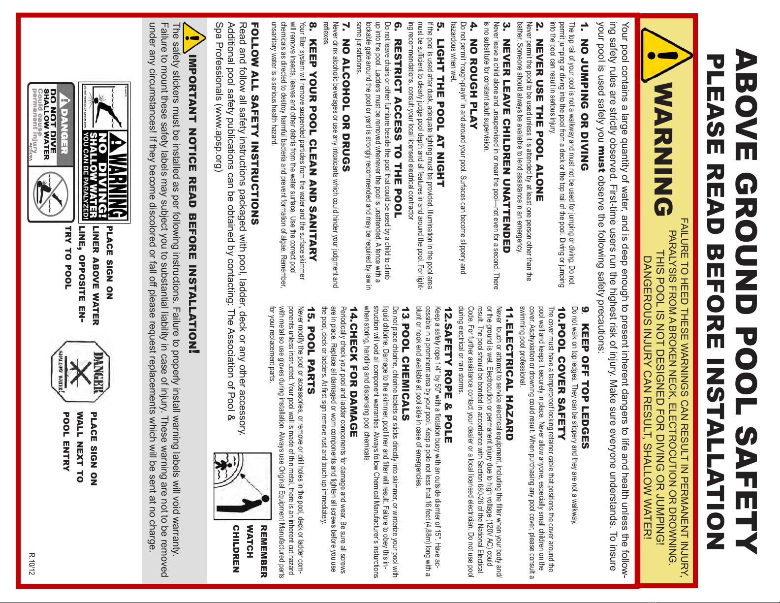
ABOVE GROUND POOL SAFETY
warning
FAILURE TO HEED THESE WARNINGS CAN RESULT IN PERMANENT INJURY,
PARALYSIS FROM A BROKEN NECK, ELECTROCUTION OR DROWNING.
THIS POOL IS NOT DESIGNED FOR DIVING OR JUMPING!
DANGEROUS INJURY CAN RESULT, SHALLOW WATER!
Your pool contains a large quantity of water, and is deep enough to present inherent dangers to life and health unless the follow-
ing safety rules are strictly observed. First-time users run the highest risk of injury. Make sure everyone understands. To insure
your pool is used safely you must observe the following safety precautions:
1. NO JUMPING OR DIVING
The top rail of your pool is not a walkway and must not be used for jumping or diving. Do not
permit jumping or diving into the pool from a deck or the top rail of the pool. Diving or jumping
into the pool can result in serious injury.
2. NEVER USE THE POOL ALONE
Never permit the pool to be used unless it is attended by at least one person other than the
bather. Someone should always be available to lend assistance in an emergency.
3. NEVER LEAVE CHILDREN UNATTENDED
Never leave a child alone and unsupervised in or near the pool—not even for a second. There
is no substitute for constant adult supervision.
4. NO ROUGH PLAY
Do not permit “rough-playin” in and around your pool. Surfaces can become slippery and
hazardous when wet.
5. LIGHT THE POOL AT NIGHT
If the pool is used after dusk, adequate lighting must be provided. Illumination in the pool area
-
ing recommendations, consult your local licensed electrical contractor
6. RESTRICT ACCESS TO THE POOL
Do not leave chairs or other furniture beside the pool that could be used by a child to climb
up into the pool. Ladders must be removed whenever the pool is unattended. A fence with a
lockable gate around the pool or yard is strongly recommended and may be required by law in
some jurisdictions.
7. NO ALCOHOL OR DRUGS
Never drink alcoholic beverages or use any intoxicants which could hinder your judgment and
8. KEEP YOUR POOL CLEAN AND SANITARY
will remove insects, leaves and other debris from the water surface. Use the correct pool
chemicals as directed to destroy harmful bacteria and prevent formation of algae. Remember,
unsanitary water is a serious health hazard.
The safety stickers must be installed as per following instructions. Failure to properly install warning labels will void warranty.
Failure to mount these safety labels may subject you to substantial liability in case of injury. These warning are not to be removed
under any circumstances! If they become discolored or fall off please request replacements which will be sent at no charge.
FOLLOW ALL SAFETY INSTRUCTIONS
Read and follow all safety instructions packaged with pool, ladder, deck or any other accessory.
Additional pool safety publications can be obtained by contacting: The Association of Pool &
Spa Professionals (www.apsp.org)
important notice read before installation!
9. KEEP OFF TOP LEDGES
Do not walk on top ledges. They can be slippery and they are not a walkway.
10.POOL COVER SAFETY
The cover must have a tamperproof locking retainer cable that positions the cover around the
pool wall and keeps it securely in place. Never allow anyone, especially small children on the
cover. Asphyxiation or drowning could result. When purchasing any pool cover, please consult a
swimming pool professional.
11.ELECTRICAL HAZARD
or the ground is wet. Electrocution or permanent injury due to high voltage (120V AC) could
result. The pool should be bonded in accordance with Section 680-26 of the National Electical
during electrical or rain storms.
12.SAFETY ROPE & POLE
Have ac-
cessible in a prominent area by your pool.
blunt or hook end available at pool side in case of emergencies.
13. POOL CHEMICALS
Do not place chlorine, chlorine tablets or sticks directly into skimmer, or winterize your pool with
liquid chlorine. -
struction will void all component warranties. Always follow Chemical Manufacturer’s insturctions
when storing, handling and dispensing pool chemicals.
14.CHECK FOR DAMAGE
Periodically check your pool and ladder components for damage and wear. Be sure all screws
are in place. Replace all damaged or worn components and tighten all screws before you use
15. POOL PARTS
Never modify the pool or accessories, or remove or drill holes in the pool, deck or ladder com-
ponents unless instructed. Your pool wall is made of thin metal, there is an inherent cut hazard
with metal so use gloves during installation. Always use Original Equipment Manufactured parts
for your replacement parts.
remember
watch
children
place sign on
liner above water
line, opposite en-
try to pool
place sign on
wall next to
pool entry
R.
PLEASE READ BEFORE INSTALLATION
7
6
5
3
2
8
9
10
11
7
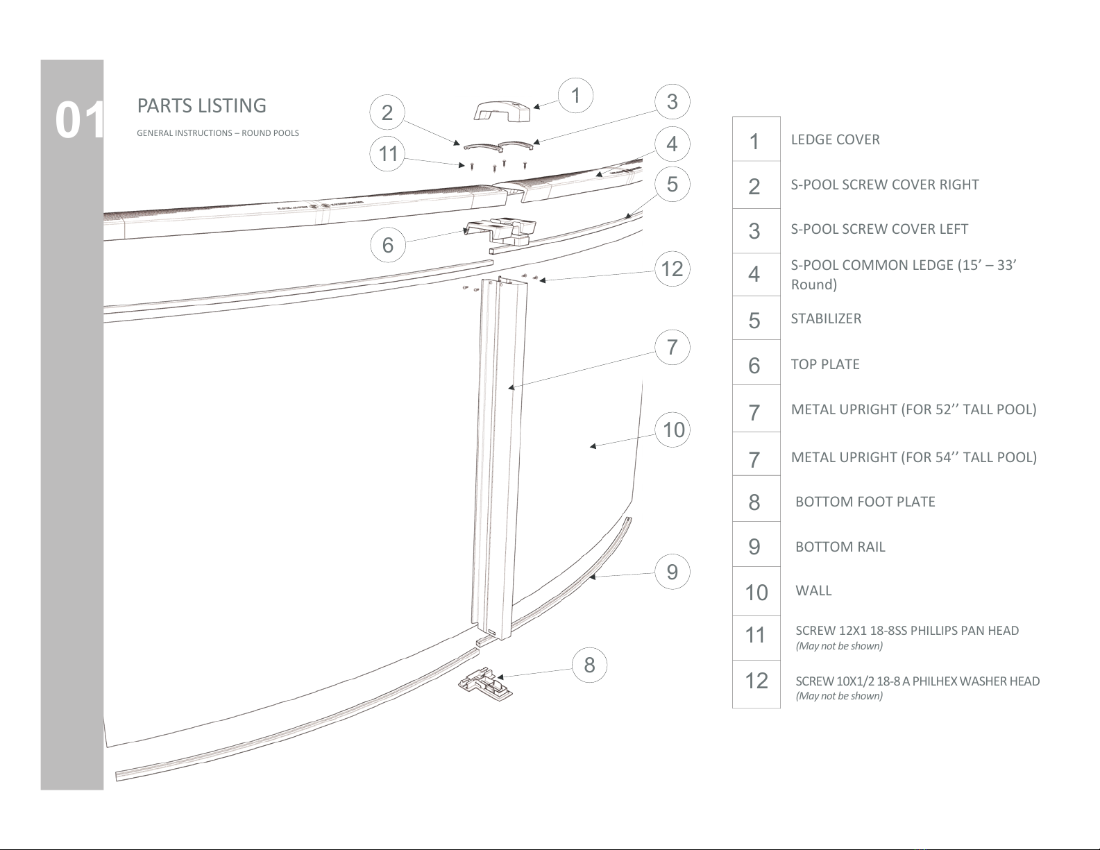
GENERAL INSTRUCTIONS – ROUND POOLS 1
12 SCREW 10X1/2 18-8 A PHILHEX WASHER HEAD
(May not be shown)
4
METAL UPRIGHT (FOR 54’’ TALL POOL)
1
2
11
3
4
5
6
12
7
10
9
8
01 PARTS LISTING
S-POOL COMMON LEDGE (15’ – 33’
Round)
LEDGE COVER
S-POOL SCREW COVER RIGHT
S-POOL SCREW COVER LEFT
BOTTOM FOOT PLATE
BOTTOM RAIL
WALL
SCREW 12X1 18-8SS PHILLIPS PAN HEAD
(May not be shown)
STABILIZER
TOP PLATE
METAL UPRIGHT (FOR 52’’ TALL POOL)
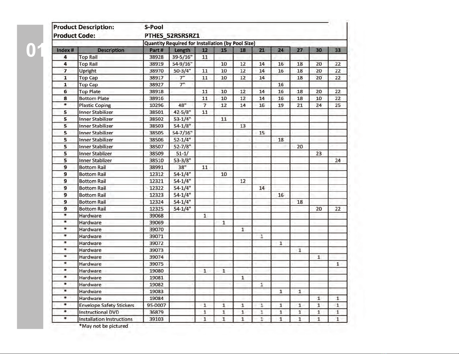
01
Descrip on Part # 15’ 18’ 21’ 24’ 27’ 30’ 33’
TOP LEDGE
S-POOL SCREW COVER RIGHT
S-POOL SCREW COVER LEFT
S-POOL COMMON RAIL (12’ Round Only)
STABILIZER
TOP PLATE
METAL UPRIGHT (FOR 52’’ TALL POOL)
BOTTOM FOOT PLATE
BOTTOM RAIL
WALL
SCREW 12X1 18-8SS PHILLIPS PAN HEAD
(May not be shown)
SCREW 10X1/2 18-8 A PHILHEX WASHERHEAD
(May not be shown)
S-POOL COMMON RAIL (15’ – 33’ Round)
METAL UPRIGHT (FOR 54’’ TALL POOL)
38917
38920
38921
38928
38919
XXXXX
38918
38970
38971
38916
XXXXX
XXXXX
99-0085
99-0068
12’
11
1
44
10
1
40
12
1
48
14
1
56
16
1
64
18
1
72
20
1
80
22
1
88
11 10 12 14 16 18 20 22
11 10 12 14 16 18 20 22
11 10 12 14 16 18 20 22
44 40 48 56 64 72 80 88
11 10 12 14 16 18 20 22
11 10 12 14 16 18 20 22
11 10 12 14 16 18 20 22
11 10 12 14 16 18 20 22
11 10 12 14 16 18 20 22
11 10 12 14 16 18 20 22
11 10 12 14 16 18 20 22
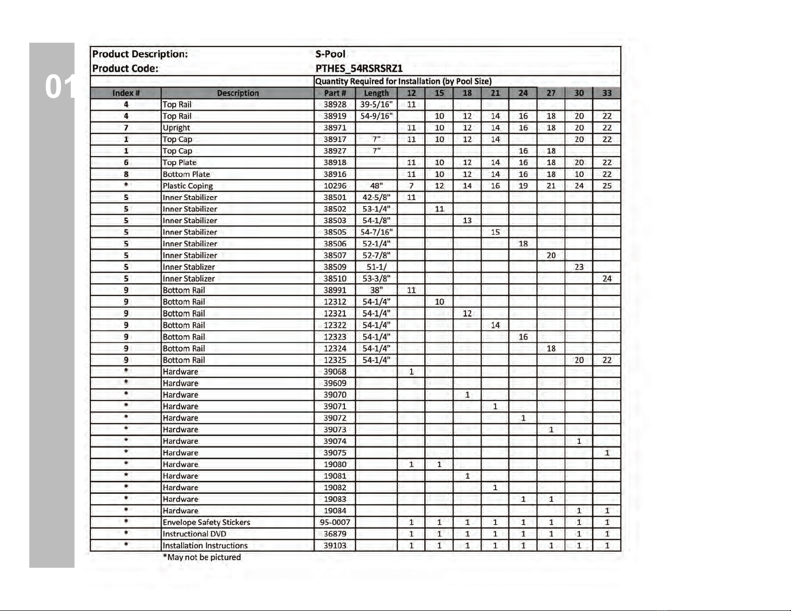
PARTS LISTING
01
Descrip on Part # 15’ 18’ 21’ 24’ 27’ 30’ 33’
TOP LEDGE
S-POOL SCREW COVER RIGHT
S-POOL SCREW COVER LEFT
S-POOL COMMON RAIL (12’ Round Only)
STABILIZER
TOP PLATE
METAL UPRIGHT (FOR 52’’ TALL POOL)
BOTTOM FOOT PLATE
BOTTOM RAIL
WALL
SCREW 12X1 18-8SS PHILLIPS PAN HEAD
(May not be shown)
SCREW 10X1/2 18-8 A PHILHEX WASHERHEAD
(May not be shown)
S-POOL COMMON RAIL (15’ – 33’ Round)
METAL UPRIGHT (FOR 54’’ TALL POOL)
38917
38920
38921
38928
38919
XXXXX
38918
38970
38971
38916
XXXXX
XXXXX
99-0085
99-0068
12’
11
1
44
10
1
40
12
1
48
14
1
56
16
1
64
18
1
72
20
1
80
22
1
88
11 10 12 14 16 18 20 22
11 10 12 14 16 18 20 22
11 10 12 14 16 18 20 22
44 40 48 56 64 72 80 88
11 10 12 14 16 18 20 22
11 10 12 14 16 18 20 22
11 10 12 14 16 18 20 22
11 10 12 14 16 18 20 22
11 10 12 14 16 18 20 22
11 10 12 14 16 18 20 22
11 10 12 14 16 18 20 22
PARTS LISTING

Check local laws on construc on and electrical installa on. Also make sure that you meet
security standards related to fences and pool cover. Select an appropriate site for your
swimming pool by considering the following points:
+ Distance from the fence
+ Overhead electrical wires
+ Predominant winds
+ Accessory loca on (lter, decking, …)
+ Appropriate electrical outlets
+ Surrounding trees (falling leaves and roots)
+ Underground cables and gas conducts
Plan your installa on rst
Be careful
+ Do not install your pool on concrete,
asphalt, wood, grass turf, top of grass,
gravel or chemically treated soil.
+ Avoid also weed and nut grass area.
+ Avoid areas with poor drainage.
+ Do not install on windy days
+ Install with 2 or 3 helpers
Ground surface and levelness: it is very important that the ground surfd.
Pool area must be free of grass, rocks roots or other sharp edged objects. Any parcel of grass
which has been treated with oil weed killer or chemical products. This could aect the vinyl
liner among other things.
: make sure you have all the parts for complete assembling
dealer to get new pieces.
DO NOT FILL LOWER GROUND AREA because any added ground won’t give the needed
strength to support pools weight.
PREPARATION
02
Above ground pools are not designed to be installed below ground level. Outside ground forces can collapse pool wall.
If you have an irregular terrain, contact your dealer for approppriate advice. Pools installed on irregular terrain ARE
NOT COVERED BY THE MANUFACTURER WARRANTY.
Be careful
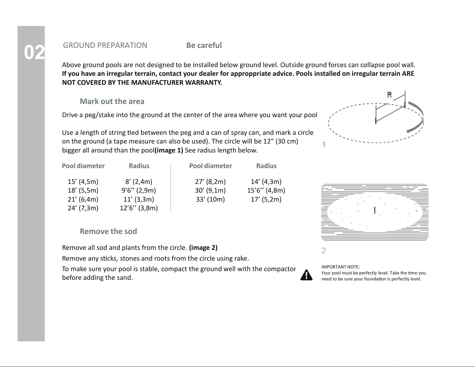
Mark out the area
Drive a peg/stake into the ground at the center of the area where you want your pool.
Use a length of string ed between the peg and a can of spray can, and mark a circle
on the ground (a tape measure can also be used). The circle will be 12” (30 cm)
bigger all around than the pool. (image 1) See radius length below.
Pool diameter
15’ (4,5m)
18’ (5,5m)
21’ (6,4m)
24’ (7,3m)
Radius
8’ (2,4m)
9’6’’ (2,9m)
11’ (3,3m)
12’6’’ (3,8m)
Pool diameter
27’ (8,2m)
30’ (9,1m)
33’ (10m)
Radius
14’ (4,3m)
15’6’’ (4,8m)
17’ (5,2m)
Remove the sod
Remove all sod and plants from the circle. (image 2)
Remove any s cks, stones and roots from the circle using rake.
To make sure your pool is stable, compact the ground well with the compactor,
before adding the sand.
IMPORTANT NOTE:
Your pool must be perfectly level. Take the me you
need to be sure your founda on is perfectly level.
GROUND PREPARATION

02
Leveling your pool site
GROUND PREPARATION
The enre pool area must be completely leveled. Level it using carpenter’s
level and a straight plank or a transit.
Nail one end of a straight 2-by-4 (5cm x 10cm) wood plank to the top of a
stake. From step 1, use a nail long enough to hold the end of the 2-by-4(5cm x 10cm)
wood plank to the stake while you rotate it in a circle.
Put a carpenter’s level on the wood plank and swing the board in a circle to
level the area. (image 3)
DO NOT ADD GROUND FOR LEVELING YOUR POOL SITE. You must dig down
to the lowest point of your pool site. Any added ground won’t give the needed
strength to support pool’s weight.
Take material such as rock dust or ne mortar that can conform a solid, permanent
base an d deposit this material around the rim of the basin. The material used should be spread
around the perimeter of the pool to a width of 24” (60cm) and a thickness of 2” (5cm).
Note: Boom rails will be placed in the center of the perimeter of the pool see the dashed line.
Lay out the boom rails and boom plates around the circle.
03
6
(image 6)
ASSEMBLING THE POOL BASE
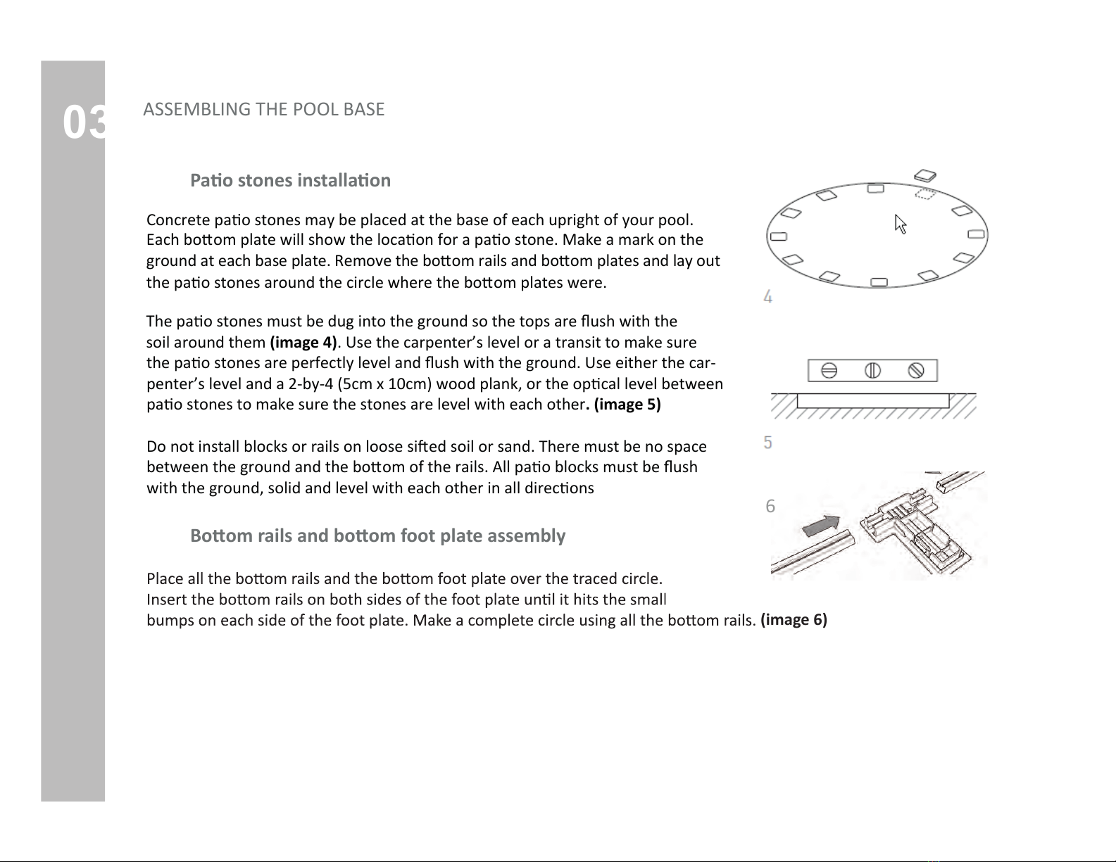
Pstones installa
Concrete pao stones may be placed at the base of each upright of your pool.
Each boom plate will show the locaon for a pao stone. Make a mark on the
ground at each base plate. Remove the boom rails and boom plates and lay out
the pao stones around the circle where the boom plates were.
The pao stones must be dug into the ground so the tops are ush with the
soil around them (image 4). Use the carpenter’s level or a transit to make sure
the pao stones are perfectly level and ush with the ground. Use either the car-
penter’s level and a 2-by-4 (5cm x 10cm) wood plank, or the opcal level between
pao stones to make sure the stones are level with each other. (image 5)
Do not install blocks or rails on loose sied soil or sand. There must be no space
between the ground and the boom of the rails. All pao blocks must be ush
with the ground, solid and level with each other in all direcons
om rom foot plate assembly

04
Pu ng up the wall
IMPORTANT NOTE:
If you use a skimmer, you should consider pu ng the pre-punched slots not too far
from the planned loca on of the lter. If you don’t use a skimmer, the pre-punched holes
must be covered with heavy fabric tape. This prevents the lining from being cut.
the pool wall: plywood, some extrto make the cove, the liner and a ladder
Make sure the skimmer and water return holes are located where you need them to be.
Unpackage the coiled pool wall and stand it on the plywood at the place close to where
you need to install skimmers. (image 8)
(image 9)
Set lengths of stabilizer onto the top ledge of the wall as you uncoil it.
DO NOT SKIP THIS STEP! Otherwise you might
end up with a slightly oval shape, which can cause problems later on. (image 7)
ASSEMBLING THE POOL WALL
04 IMPORTANT NOTE:
It is preferable to use very ne sand that is easily compacted.
Be careful not to spill sand on the bo om rails.
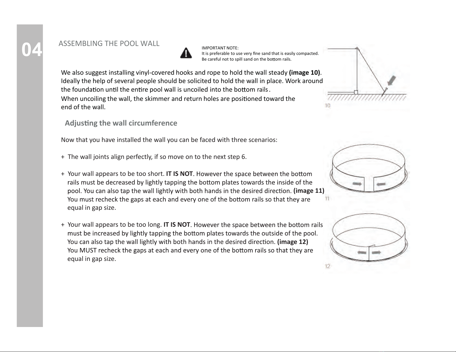
We also suggest installing vinyl-covered hooks and rope to hold the wall steady (image 10).
Ideally the help of several people should be solicited to hold the wall in place. Work around
the founda on un l the en re pool wall is uncoiled into the bo om
rails
.
When uncoiling the wall, the skimmer and return holes are posi oned toward the
end of the wall.
Adjus ng the wall circumference
Now that you have installed the wall you can be faced with three scenarios:
+ The wall joints align perfectly, if so move on to the next step 6.
+ Your wall appears to be too short. IT IS NOT
(image 11)
equal in gap size.
+ Your wall appears to be too long. IT IS NOT
(image 12)
equal in gap size.
ASSEMBLING THE POOL WALL

04
IMPORTANT NOTE:
Sck a screwdriver through two of the holes
to help line up the ends of the walls.
Cover the seam and bolt heads on the inside/interior of the pool wall completely with 2’ (50 cm)
duct tape. (image 14)
The pool wall must be round. Adjust the circle by nudging the base plates in or out with your foot.
(image 15)
ASSEMBLING THE POOL WALL
Fasten and seal the wall
tening the screws start from either the top and go down or vice versa. Do not start
necessary. (image 13)
IMPORTANT NOTE:
Due to the enormous pressure exerted against the steel wall, it is absolutely essenal to screw
ALL THE BOLT TIGHTLY. DO NOT LEAVE ANY EMPTY HOLES. Bolt heads must be inside and nuts
outside. Remove all parcles of metal from the bolts inside the pool.
+ Make sure that the steel wall is securely resng
+ Make sure the steel wall is leaning on the inward edge of the
+ Make sure that all boom rails are properly joined inside the post bases.
+ Make sure the wall makes a perfect circle by measuring across the the circle

04
A vacuum cleaner can later be used to remove the air from between the liner
and the wall (image 17). This technique enables you to remove folds on the
liner. However do not use an industrial vacuum cleaner which could be too powerful.
The following steps should be taken:
+ Tape the end of the vacuum hose before inser ng it into the wall so as not to damage the liner.
+ Insert the nozzle un l it is about 4” (10cm) above the cove (insert through the water return outlet or the
skimmer depending on the diameter of your hose.) Make sure you will be able to remove the hose later on.
+ Tape the hose to the wall.
ASSEMBLING THE POOL WALL
Pung down the pool base and cove
You must spread a sand base down across the re bom of the pool. The base should be
2" to 3" deep (5 cm - 7.5 cm). Along the inside of the pool wall you must form a pool cove that
is 3" to 4"
from sharp objects that may penetrate the liner. The cove will protect the liner from sharp
objects and will prevent the liner from creeping under the wall. Use a trowel to smooth the
sand. Water sand down to compact it. (image 16)
DO NOT USE THIN SAND. GRASS TURF OR ANY OTHER MATERIAL THAT CAN CAUSE
DAMAGES TO YOUR POOL. THE LINER COULD EVENTUALLY RUPTURE.
The cove is very important. THE MANUFACTURER WILL NOT BE RESPONSIBLE FOR DAMAGES
CAUSED BY OMISSION OF THIS STEP.
If you are using Styrofoam cove pieces instead of sand, insert them in the boom
rail and refer to the installaon instrucons that are provided with them.
Vinyl liner inston
05
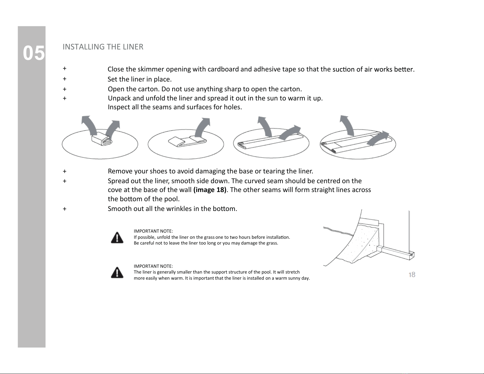
Close the skimmer opening with cardboard and adhesive tape so that the
Set the liner in place.
+
+
+
Open the carton. Do not use anything sharp to open the carton.
+ Unpack and unfold the liner and spread it out in the sun to warm it up.
Inspect all the seams and surfaces for holes.
+ Remove your shoes to avoid damaging the base or tearing the liner.
+ Spread out the liner, smooth side down. The curved seam should be centred on the
cove at the base of the wall (image 18). The other seams will form straight lines across
the bo om of the pool.
+ Smooth out all the wrinkles in the bo om.
IMPORTANT NOTE:
If possible, unfold the liner on the grass one to two hours before installa on.
Be careful not to leave the liner too long or you may damage the grass.
IMPORTANT NOTE:
The liner is generally smaller than the support structure of the pool. It will stretch
more easily when warm. It is important that the liner is installed on a warm sunny day.
INSTALLING THE LINER
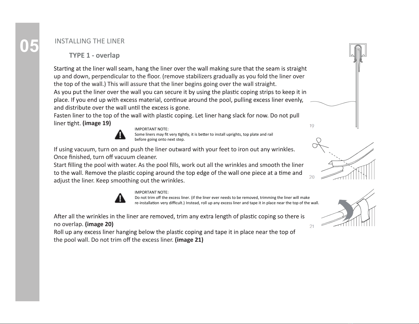
05 TYPE 1 - overlap
IMPORTANT NOTE:
Some liners may t very ghtly, it is be er to install uprights, top plate and rail
before going onto next step.
IMPORTANT NOTE:
Do not trim o the excess liner. (if the liner ever needs to be removed, trimming the liner will make
re-installa on very dicult.) Instead, roll up any excess liner and tape it in place near the top of the wall.
up and down, perpendicular tr. (remove stabilizers gradually as you fold the liner over
the top of the wall.) This will assure that the liner begins going over the wall straight.
(image 19)
If using vacuum, turn on and push the liner outward with your feet to iron out any wrinkles.
vacuum cleaner.
Stng the pool with water. As the pool work out all the wrinkles and smooth the liner
adjust the liner. Keep smoothing out the wrinkles.
no overlap. (image 20)
the pool wexcess liner. (image 21)
INSTALLING THE LINER
05
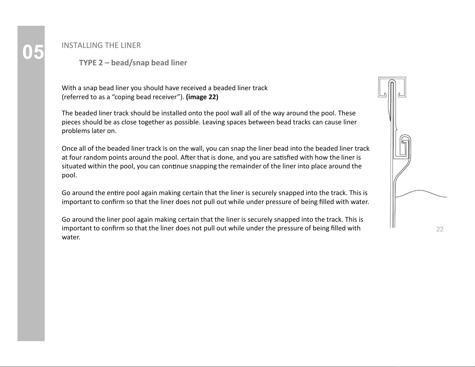
TYPE 2 – bead/snap bead liner
With a snap bead liner you should have received a beaded liner track
(referred to as a “coping bead receiver”). (image 22)
The beaded liner track should be installed onto the pool wall all of the way around the pool. These
pieces should be as close together as possible. Leaving spaces between bead tracks can cause liner
problems later on.
Once all of the beaded liner track is on the wall, you can snap the liner bead into the beaded liner track
at four random points around the pool. A er that is done, and you are sa sed with how the liner is
situated within the pool, you can con nue snapping the remainder of the liner into place around the
pool.
Go around the en re pool again making certain that the liner is securely snapped into the track. This is
important to conrm so that the liner does not pull out while under pressure of being lled with water.
Go around the liner pool again making certain that the liner is securely snapped into the track. This is
important to conrm so that the liner does not pull out while under the pressure of being lled with
water.
INSTALLING THE LINER

05
TYPE 3 – hung/J or V-bead line
The top of the wall of the liner has what is called a “V-Bead” welded onto it. Simply open up the
bead with your ngers and hang it directly on top of the pool wall. (image 23) When this is done
properly, the only por on on the outside of the pool wall is approximately 1” of the V-Bead.
No printed liner material is actually going over the top of the wall to the outside of the wall.
Make sure the bead is on evenly around the en re pool, and that the liner is hanging straight down
from the top of the wall. The liner should not have creases in it, if there are creases it is because
Make the necessary adjustments before proceeding.
IMPORTANT NOTE:
Some liners may t very ghtly, it is be er to install uprights, top plate and rail
before going onto next step.
IMPORTANT NOTE:
Do not trim o the excess liner. (if the liner ever needs to be removed, trimming the
liner will make re-installa on very dicult.) Instead, roll up any excess liner and tape
it in place near the top of the wall.
INSTALLING THE LINER
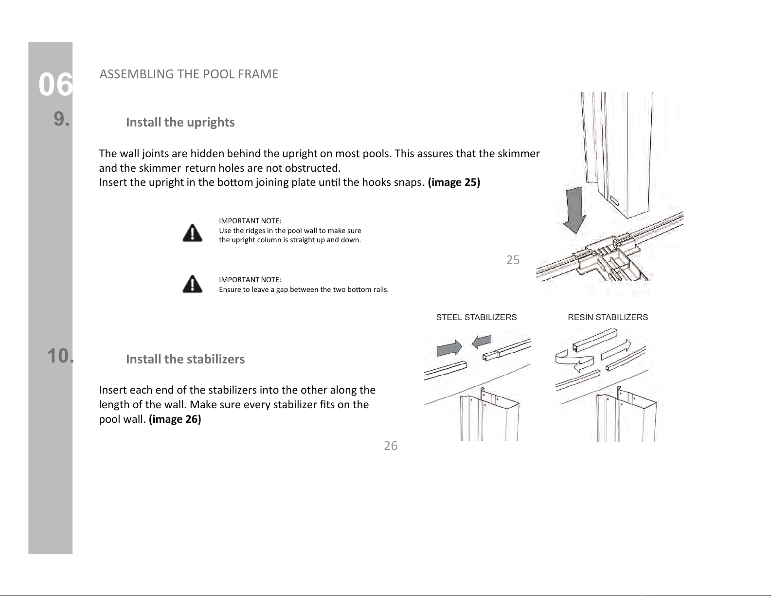
06
Install the uprights
9.
The wall joints are hidden behind the upright on most pools. This assures that the skimmer
and the skimmer return holes are not obstructed.
Insert the upright in the bo om joining plate un l the hooks snaps. (image 25)
IMPORTANT NOTE:
Use the ridges in the pool wall to make sure
the upright column is straight up and down.
IMPORTANT NOTE:
Ensure to leave a gap between the two bo om rails.
Install the stabilizers
10.
25
26
ASSEMBLING THE POOL FRAME
Insert each end of the stabilizers into the other along the
length of the wall. Make sure every stabilizer ts on the
pool wall. (image 26)
STEEL STABILIZERS RESIN STABILIZERS
06
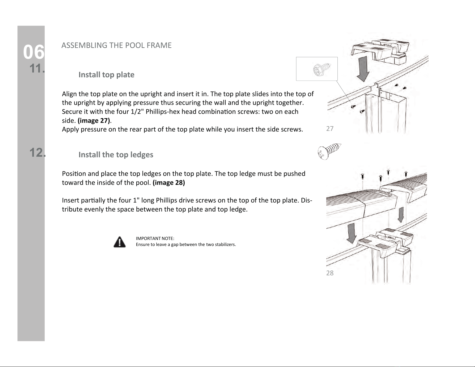
Install the top ledges
12.
IMPORTANT NOTE:
Ensure to leave a gap between the two stabilizers.
Install top plate
27
28
ASSEMBLING THE POOL FRAME
Posion and place the top ledges on the top plate. The top ledge must be pushed
toward the inside of the pool. (image 28)
Insert parally the four 1" long Phillips drive screws on the top of the top plate. Dis-
tribute evenly the space between the top plate and top ledge.
Align the top plate on the upright and insert it in. The top plate slides into the top of
the upright by applying pressure thus securing the wall and the upright together.
Secure it with the four 1/2"
side. (image 27).
Apply pressure on the rear part of the top plate while you insert the side screws.
11.
06
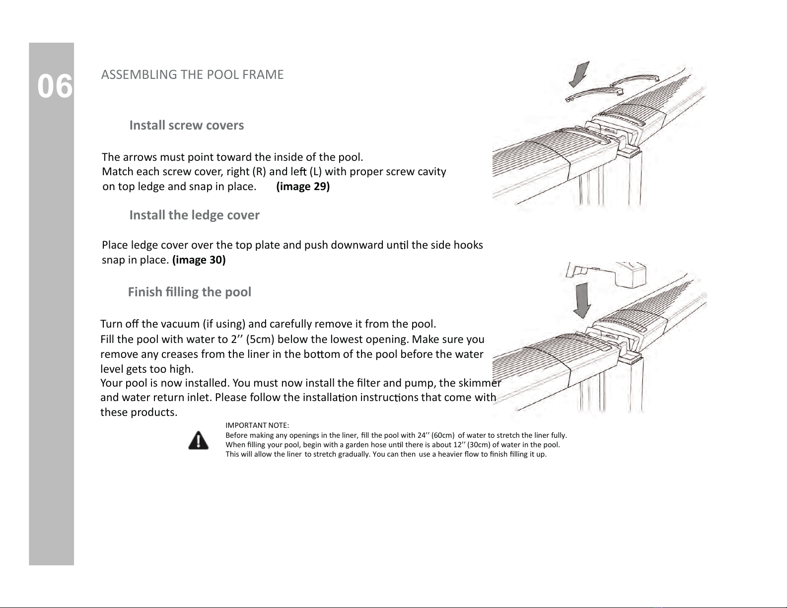
Install the ledge cover
Place ledge cover over the top plate and push downward un l the side hooks
snap in place. (image 30)
Install screw covers
The arrows must point toward the inside of the pool.
Match each screw cover, right (R) and le (L) with proper screw cavity
on top ledge and snap in place. (image 29)
29
30
Finish lling the pool
Turn o the vacuum (if using) and carefully remove it from the pool.
Fill the pool with water to 2’’ (5cm) below the lowest opening. Make sure you
remove any creases from the liner in the bo om of the pool before the water
level gets too high.
Your pool is now installed. You must now install the lter and pump, the skimmer
and water return inlet. Please follow the installa on instruc ons that come with
these products.
IMPORTANT NOTE:
Before making any openings in the liner, ll the pool with 24’’ (60cm) of water to stretch the liner fully.
When lling your pool, begin with a garden hose un l there is about 12’’ (30cm) of water in the pool.
This will allow the liner to stretch gradually. You can then use a heavier ow to nish lling it up.
ASSEMBLING THE POOL FRAME
This manual suits for next models
1
Table of contents
Other Sharkline Swimming Pool manuals


