USB LANPORT 100/400
4. Getting started
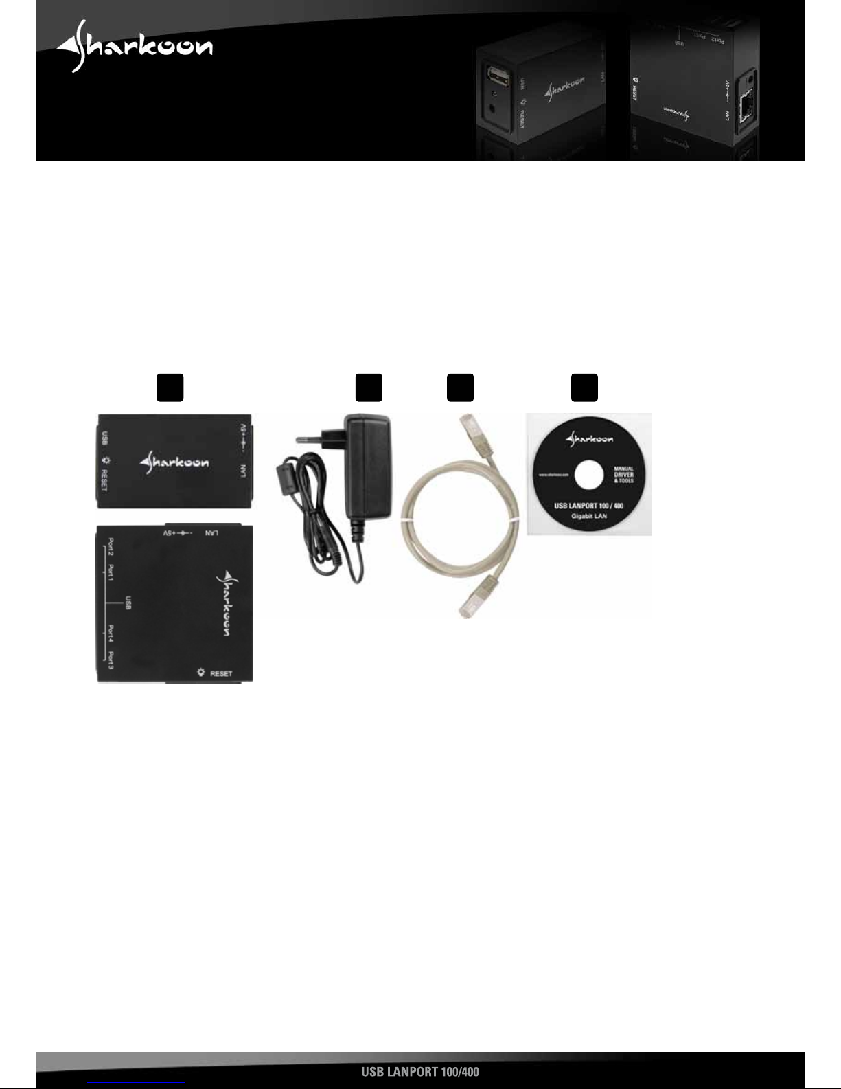
4.1 Hardware installation
1. ConnecttheincludedpatchcabletotheUSBLANPort’snetworkconnectorandanavailablenetworkconnectorofyour
switch/hub/router/PCorsimilar.
2. ConnecttheincludedpoweradaptertotheUSBLANPortandawalloutlet.Thedevicewillbootautomatically.
4.2 Software installation (Windows for example)
1. InserttheincludedToolsCDintoyourCD/DVDdrive.
2. Use the Windows Explorer to open the directory of the insertedTools CD.
3. Double click (left mouse button) “Setup.exe”. The installation procedure will start. Follow the installation wizard’s
instructions.
4. To complete the installation you will be prompted to reboot your PC. Confirm this indication.
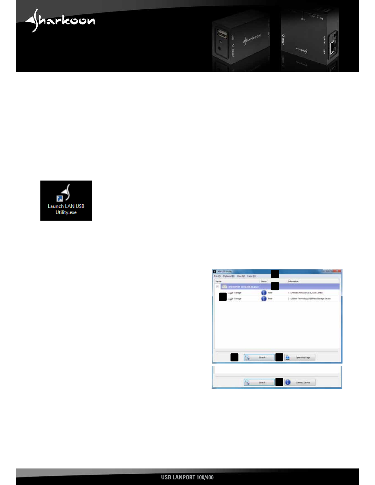
5. Aftersuccessfullyrebootingyoursystem,thefollowingiconwillappearonyourdesktop:
Double-click(leftmousebutton)thisicontolaunchthesoftware.
Note:
You need to install this server software on every PC from which you want to access the USB LANPort.
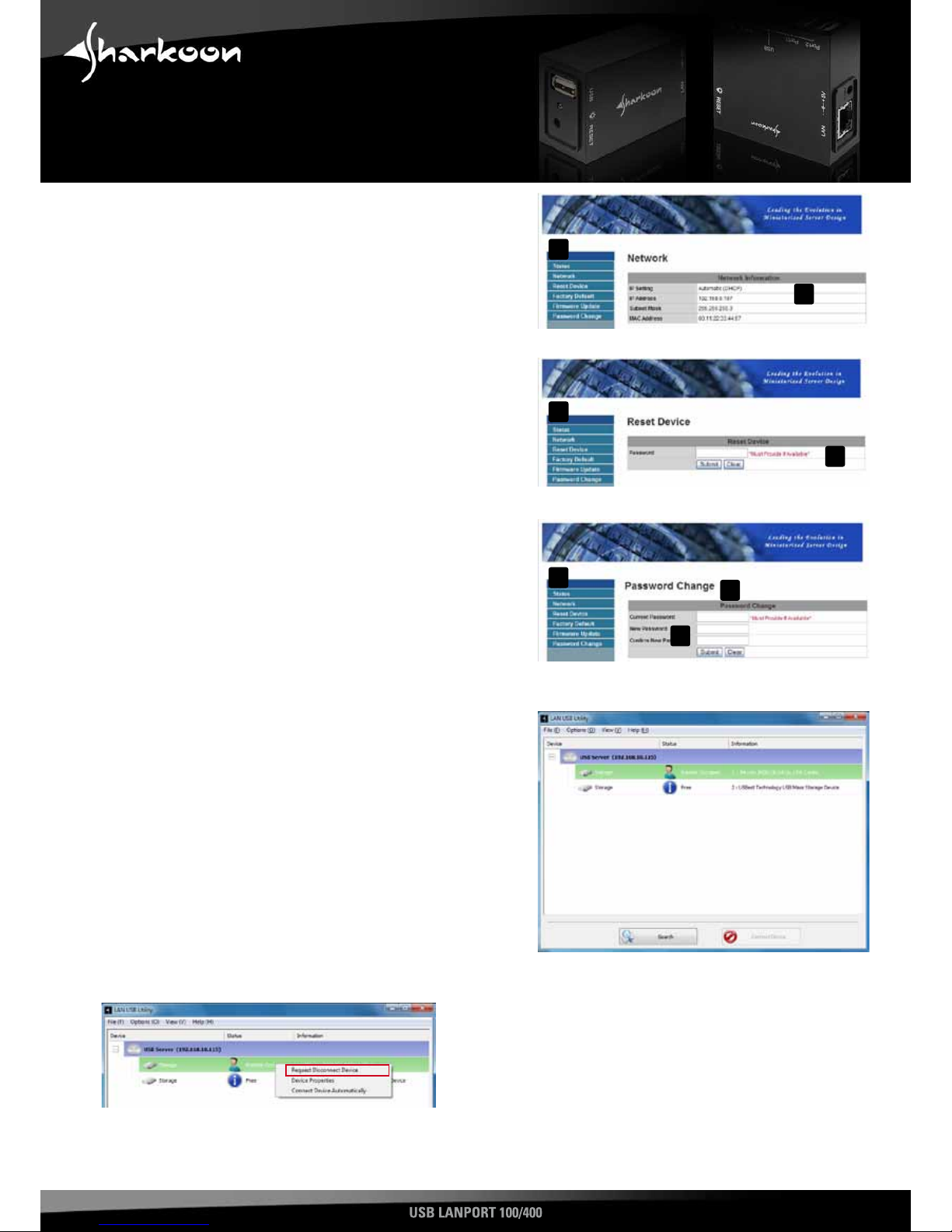
5. The user interface
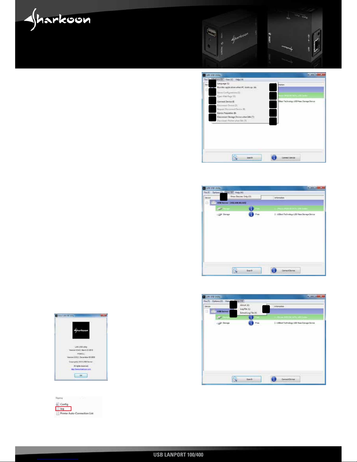
A – Menubarshowingtheentries“File“,“Options“,“View“
and “Help“
B – USBserverwithrelatedIPaddress
C – USBdevicesconnectedtotheUSBserver
D – “Search”button:byleft-clickingasearchrunis
commenced, to detect devices connected to the USB
server
E – “OpenWebPage”button(onlydisplayedwhentheUSB-
Serverisselected):byleft-clickingtheUSBserver’sweb
interface will be opened
F – “Connectdevice”button(onlydisplayedwhenaplugged
USBdeviceisselected):byleft-clickingthisbuttonthe
respective USB device is connected and locked for other
users
Note:
The software will detect the connected USB server and associated devices automatically. Furthermore the USB server
supports automatic and manual IP address assignment; automatic address assignment via DHCP is selected by default.
In case your firewall prompts you during the installation process allow the USB server to access the respective network
resources.
A
D E
B
C
F
3