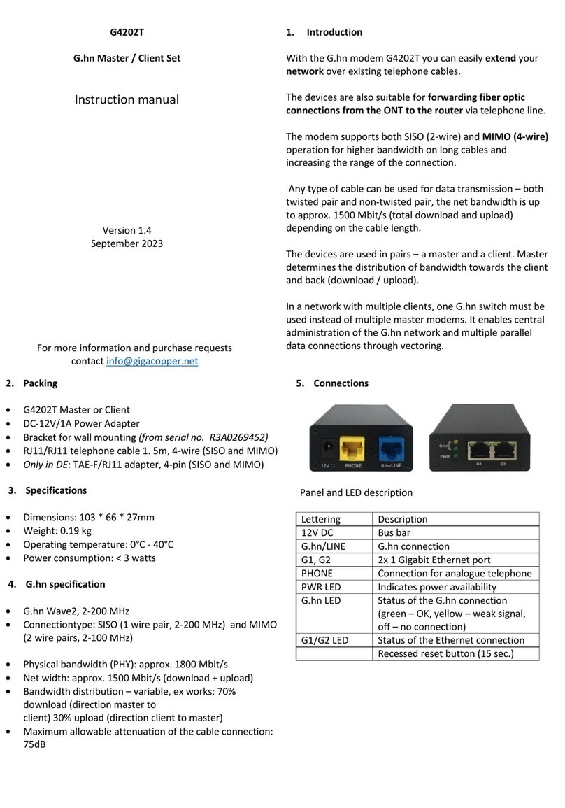
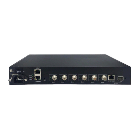
GIGA G4202TCP User manual

1
G4202TCP
Quick Installation Guide
GIGA Copper Networks GmbH

2
1. Package List
G4202TCP*1 pcs Screw kits*2 pcs Installation tag*1 pcs
2. Hardware Introduction
2.1 Physical and Environmental
⚫Dimension: 107mm (L)*77mm (W)*38mm (H)
⚫Weight: 340g
⚫Operating temperature: 0~50℃
⚫Storage temperature: -25℃~ 70℃
⚫Humidity: 10% ~ 90% RH Non-condensing
⚫Maximum power consumption: <5w (Without PoE load)
2.2 Front Panel
The front panel of the G4202TCP contains 1 *RJ45/F-Type coaxial connector of G.hn
port with PoC, 2 *10/100/1000Base-T RJ45 Ethernet port and a USB Type-C
connector for extra power supply.

3
2.3 Rear Panel
2.4 LED Indicators
Label
Type
Color
Stat
e
Description
PWR
Power Status
Yellow
On
Lights to indicate the power is on
Off
Indicate the power is off
LINE
G.hn link status
Green
On
Lights to indicate the coaxial/UTP link
is established
Off
Indicates that the coaxial/UTP link is
down
Yellow
On
Lights to indicate the coaxial/UTP link
status is poor
Off
Indicates that the coaxial/UTP link
status is normal or indicates the
coaxial/UTP is link down (it can be
judged from the G.hn green LED
status)
G1/G2
Ethernet link
status
Green
On
Lights to indicate the port is link up and
the rate is 1000Mbps
Off
Indicates that the port is link down or
the port is link up but connect rate is
10/100 Mbps
Yellow
On
Lights to indicate the port is link up
Off
Indicates that the port is link down
Blink
The port is up and has data
transmission

4
3. Hardware Specifications
Label
Description
20V/3A
AType-C connector for USB-PD 20V/3ADC input
PWR IN / LINE
G.hn combo port, 1* RJ45 connector and 1*F-type
coax connector alternative, and both of them support
PoC
G1/G2
2 *10/100/1000Base-T RJ45 Ethernet ports with
802.3af/at PoE+
MDI/MDI-X selection: automatic
Cable specification: CAT5 or CAT6 UTP
RST
Press and hold the RST button on the front panel
beyond 15s to reset G4202TCP to factory default
configuration
4. Application and Installation
Long Reach POE solution is designed to extend IP Ethernet transmission and inject
power into a remote 8.2.3af/at PoE compliant power device (PD) beyond the 100 meters
limit of Ethernet.
The G4202TCP supports 2 ways as power source to inject 802.3af/at PoE to remote
standard PDs (power Devices)
⚫Remote G4202TCP power supplied from Headend G4224 switch over coaxial cable
or UTP cable.
⚫Local DC power from power supply through G4202TCP’s USB Type-C connector.
Note
Before installation, please consider the distance and watts value
demand for PD devices. The G4202TCP output capacity and
upload/download performance depends on the length of the UTP and
coaxial cable
Note
The G4202TCP has two power input options. Only one mode is
available at the same time, when both local DC power and remote
G.hn power provide power for G4202TCP, it is recommended to
connect the local DC power first, and then remote G.hn power.

5
Typical Application 1:
The G4202TCP is powered via PoC, power supply from G4224, the IEEE 802.3af/at
compliant PoE PD will automatically be powered by the G4202TCP via UTP/Coaxial
Remote Power from G4224 over UTP Cable:
UTP
802.3af/at PoE
Power over UTP
100-240V AC
Ethernet Switch
PoE IP Camera
Up to 600m
G4224
G4202TCP
Functions
PoE+ Extender
G4202TCP
Power Input
G.hn port with IEEE 802.3af/at/bt PoE input over UTP
Power Output
G1/G2 RJ45 port with IEEE 802.3af/at PoE output
Installation Instruction:
Step1. Connect 100-240VAC to the PoC Injector (G4224)
Step2. Connect the PoC injector (G4224) and PoE+ extender (G4202TCP) to ends of
RJ45 terminated UTP cable, then the G4202TCP will be powered on and the PWR LED
will lit up accordingly.
Step3. Connect Cat5/Cat6 UTP cable to G4202TCP and IEEE 802.3af/at complied PoE
IP camera or other PD devices.
Remote Power from G4224 over Coaxial Cable:
802.3af/at PoE
100-240V AC
Ethernet Switch
PoE IP Camera
Coaxial
20V/3A DC Power
Input
Up to 500m
G4224
G4202TCP

6
Functions
PoE+ Extender
G4202TCP
Power Input
G.hn port with PoC power input over Coaxial
Power Output
G1/G2 RJ45 port with IEEE 802.3af/at PoE output
Installation Instruction:
Step1. Connect 100-240VAC to the PoC Injector (G4224)
Step2. Connect the PoE+ injector (G4224) and PoE+ extender (G4202TCP) via coaxial
cable, then the G4202TCP will be powered on and the PWR LED will lit up accordingly.
Step3. Connect Cat5/Cat6 UTP cable to G4202TCP and IEEE 802.3af/at complied PoE
IP Camera or other PD devices.
Typical Application 2:
The G4202TCP is powered via the external power. An IEEE 802.3af/at compliant PoE PD
will automatically be powered by the G4202TCP via UTP/coaxial (connect to G4224)
Local DC Power through G4202TCP’s USB Type-C Connector (UTP Application),
Connect to G4224:
UTP
802.3af/at PoE
Power over UTP
100-240V AC
Ethernet Switch
PoE IP Camera
Up to 600m
20V/3A DC
Power Input
G4224
G4202TCP
Functions
PoE+ Extender
G4202TCP
Power Input
20V/3ADC power input via USB Type-C connector
Power Output
G1/G2 RJ45 port with IEEE 802.3af/at PoE output
Installation Instruction:
Step1. Connect 100-240VAC to the PoC Injector (G4224)
Step2. Connect a 20V/3ADC power to the USB Type-C connector, the G4202TCP will
power on and the PWR LED will lit up immediately.
Step3. Connect the PoE+ injector (G4224) and PoE+ extender (G4202TCP) to ends of
RJ45 terminated UTP cable.
Step4. Connect Cat5/Cat6 UTP cable to G4202TCP and IEEE 802.3af/at complied PoE
IP camera or other PD devices.

7
Local DC Power through G4202TCP’s USB Type-C Connector (Coax
Application), Connect to G4224:
UTP
802.3af/at PoE
100-240V AC
Ethernet Switch
PoE IP Camera
Coaxial
20V/3A DC Power
Input
Up to 500m
G4202TCP
G4224
Functions
PoE+ Extender
G4202TCP
Power Input
20V/3ADC power input via USB Type-C connector
Power Output
G1/G2 RJ45 port with IEEE 802.3af/at PoE output
Step1. Connect 100-240VAC to the PoC Injector (G4224)
Step2. Connect a 20V/3ADC power to the USB Type-C connector, the G4202TCP will
power on and the PWR LED will lit up immediately.
Step3. Connect the PoE+ Injector (G4224) and PoE+ Extender (G4202TCP) via coaxial
cable.
Step4. Connect Cat5/Cat6 UTP cable to G4202TCP and IEEE 802.3af/at complied PoE
IP camera or other PD devices.
Typical Application 3:
The G4202TCP is powered via the external power, and the IEEE 802.3af/at compliant
PoE PD will automatically be powered by the G4202TCP via UTP/Coaxial (connect to
G4202TCP)
Local DC Power through G4202TCP’s USB Type-C Connector (UTP Application),
Connect to G4202TCP (Local):
UTP
802.3af/at PoE
Ethernet Switch
PoE IP Camera
UTP
20V/3A DC Power
Input
Up to 600m
20V/3A DC Power
Input
G4202TCP G4202TCP

8
Functions
PoE+ Extender
G4202TCP
Power Input
20V/3ADC power input via USB Type-C connector
Power Output
G1/G2 RJ45 port with IEEE 802.3af/at PoE output
Installation Instruction:
Step1. Connect a 20V/3ADC to the USB Type-C connector (G4202TCP local)
Step2. Connect a 20V/3A DC power to the USB Type-C connector (G4202TCP remote),
the G4202TCP remote will power on and the PWR LED will lit up immediately.
Step3. Connect the G4202TCP (local) and G4202TCP (remote) via UTP cable.
Step4. Connect Cat5/Cat6 UTP cable to G4202TCP (remote) and IEEE 802.3af/at
complied PoE IP Camera or other PD devices.
Local DC Power through G4202TCP’s USB Type-C connector (Coaxial Application),
Connect to G4202TCP (Local):
UTP
802.3af/at PoE
Ethernet Switch
PoE IP Camera
Coaxial
20V/3A DC Power
Input
Up to 500m
20V/3A DC Power
Input
G4202TCP G4202TCP
Functions
PoE+Extender
G4202TCP
Power Input
20V/3ADC power input via USB Type-C connector
Power Output
G1/G2 RJ45 port with IEEE 802.3af/at PoE output
Installation Instruction:
Step1. Connect a 20V/3ADC to the USB Type-C connector (G4202TCP local)
Step2. Connect a 20V/3A DC power to the USB Type-C connector (G4202TCP remote),
the G4202TCP remote will power on and the PWR LED will lit up immediately.
Step3. Connect the G4202TCP (local) and G4202TCP (remote) via coaxial cable.
Step4. Connect Cat5/Cat6 UTP cable to G4202TCP (remote) and IEEE 802.3af/at
complied PoE IP Camera or other PD devices.

9
5. Mounting Procedures
The G4202TCP can be mount installed on a chassis/wall, there are 2 hangers on the
rear panel of G4202TCP with shipment for mount installation as following picture
shows:
Hangers for Installation
Rear Panel
Step1. Remove four mounting fin screws on the back panel as shown below.
Step2. Turn over the fins and restore the four screws back to the back panel as shown
below

10
Step3. For brick and cement wall, place the G4202TCP to the proper location where it is
going to be installed, use a marker or pen to identify the hole locations
Step4. Follow the marked hole location, drill four holes using 6mm drill tip and nail in four
plastic wall-mount nuts into the holes, then mount the G4202TCP on the wall with four
wall-mount screws.
For the wall or location where the screws can be screwed in directly, the G4202TCP can
be mounted with four wall-mount screws without the need of plastic wall-mount.
Warming
Must use the M3*4 standard screws to tighten the hangers
6. Performance
6.1 Test Condition:
Items
Description
UTP Cable
0.5mm 25pair F/S cable
Coaxial Cable
SYV 75-4 100m, SYV 75-5 200m
Test Tool
Big Tao 200 Tester

11
6.2 Performance
Following charts show the performance and PoE output capability test results in different
cable length
Coaxial
Performance
Distance
(meter)
Throughput(Download/Upload):
Mb/s
Packet Length:512Bytes
802.3af/at/bt PoE Output
Capability
Remote power
through F-type
coax connector
Local DC power
through USB
Type-C
connector
Remote
power
through
F-type coax
connector
Local DC
power through
USB Type-C
connector
1
990/440
990/440
30w
30w
100
990/440
990/430
30W
30w
200
860/390
740/320
18W
30w
300
560/290
540/270
11W
30w
400
370/220
220/140
9W
30w
500
170/130
160/130
7W
30w
UTP
Performance
(MIMO)
Distance
(meter)
Throughput(Download/Upload):
Mb/s
Packet Length:512Bytes
802.3af/at/bt PoE Output
Capability
Remote power
through UTP
connector
Local DC power
through USB
Type-C
connector
Remote
power
through UTP
connector
Local DC
power through
USB Type-C
connector
1
990/440
990/440
30w
30w
100
990/440
990/440
30w
30w
200
980/410
980/410
21w
30w
300
760/250
740/190
13w
30w
400
500/150
490/140
9w
30w
500
310/80
300/80
6w
30w
600
210/40
200/40
4w
30w
UTP
Performance
(SISO)
Distance
(meter)
Throughput(Download/Upload):
Mb/s
Packet Length:512Bytes
802.3af/at/bt PoE Output
Capability
Remote power
through UTP
connector
Local DC power
through USB
Type-C
connector
Remote
power
through UTP
connector
Local DC
power through
USB Type-C
connector

12
1
990/450
990/450
30w
30w
100
990/430
990/430
18w
30w
200
650/250
630/250
9w
30w
300
270/130
250/130
5w
30w
400
140/80
30w
500
80/50
30w
600
40/30
30w
The above PoE output capability results is measured on Ghn11/Ghn12 or Ghn23/Ghn24
of the G4224 which support 802.3bt PoE output, also the G4202TCP support 802.3bt PoE
input.
Note: The actual data rate will vary on the quality of the copper wire and environment
factors.
Depending on what the DC/PoE Power Input and the length of coaxial/UTP cable
7. Appendix A: RJ45 Pin Assignments
RJ45 Pin Assignments
Contact
POE
1
Positive(VCC+)
2
Positive(VCC+)
3
Positive(VCC+)
4
Positive(VCC+)
5
Negative(VCC-)
6
Negative(VCC-)
7
Negative(VCC-)
8
Negative(VCC-)
Table of contents
Other GIGA Network Hardware manuals
Popular Network Hardware manuals by other brands

Panasonic
Panasonic Chip RC Networks EZACT Application guide

Kanguru
Kanguru iNAS-100 user manual

Omron
Omron CQM1H-SCB41 Operation manual

Koukaam
Koukaam KNR-5016 Quick installation guide

Datacom Systems
Datacom Systems VS-1112-F Fast start guide

United Technologies
United Technologies TruVision NVR 21S quick start guide

CAME
CAME 803XC-0020 manual

Overland Storage
Overland Storage NEO instructions

Network Appliance
Network Appliance C1200 NetCache Service guide

ADTRAN
ADTRAN Ethernet Over Bonded Copper MX3112 Specification sheet

Avadesign
Avadesign avaControl-100 Installation and user guide

Aaeon
Aaeon UP Element i12 EDGE user manual