Gude Expert Power Control 1100 User manual

© 2012 Gude Analog- und Digitalsysteme GmbH
Expert Power Control 1100/1101

Expert Power Control 1100/1101
© 2012 Gude Analog- und Digitalsysteme
GmbH
06.08.2012

3Table of content
Expert Power Control 1100/1101
Table of content
Chapter 1 Safety Advice 5
Chapter 2 Description 5
Chapter 3 Hardware 5
5
3.1 Content of delivery
6
3.2 Connections
6
3.3 Installation
6
3.4 Status LED
Chapter 4 Configuration 7
7
4.1 DHCP
7
4.2 Network settings with GBL_Conf
8
4.3 Configuration via webinterface
4.3.1 Configuration - Power Ports 8
4.3.2 Watchdog 9
4.3.3 Configuration - IP Address 10
4.3.4 Configuration - IP ACL 11
4.3.5 Configuration - HTTP 12
4.3.6 Configuration - Messages 13
4.3.7 Configuration - SNMP 14
4.3.8 Configuration - Syslog 15
4.3.9 Configuration - E-Mail 16
Chapter 5 Operation 17
17
5.1 Switching at the device
17
5.2 Switching by Webinterface
5.2.1 Control Panel 17
18
5.3 Sensor
19
5.4 Energy Measurement
Chapter 6 Features 19
19
6.1 Bootloader mode
19
6.2 Firmware update
20
6.3 Technical information

5
Expert Power Control 1100/1101 Safety Advice
1 Safety Advice
The device must be installed only by qualified personnel according to the following installation and operating instructions.
The manufacturer does not accept responsibility in case of improper use of the device and particularly any use of equipment
that may cause personal injury or material damage.
The device contains no user-maintenable parts. All maintenance has to be performed by factorytrained service personnel.
Check if the power cord, the plug and the socket are in proper condition.
The device can be connected only to 230V AC (50 or 60 Hz) sockets.
Always connect the device to properly grounded power sockets.
The device is intended for indoor use only. Do NOT install them in an area where excessive moisture or heat is present.
Because of safety and approval issues it is not allowed to modify the device without our permission.
Please note the safety advises and manuals of connected devices, too.
The device is NOT a toy. It has to be used or stored out or range of children.
Packaging material is NOT a toy. Plastics has to be stored out of range of children. Please recycle the packaging materials.
In case of further questions, about installation, operation or usage of the device, which are not clear after reading the manual,
please do not hesitate to ask our support team.
Please, never leave connected equipment unattended, that can cause damage (e.g. iron heater, etc.).
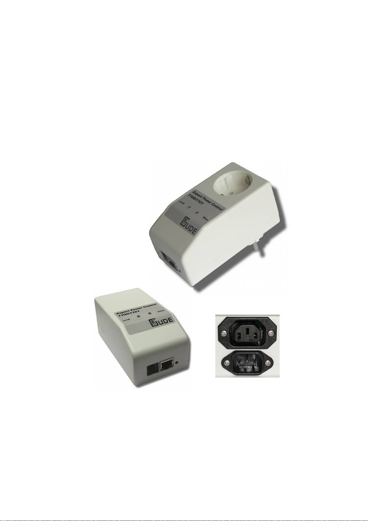
2 Description
The Expert Power Control 1100/1101 facilitates the remote switching of electrical devices via a TCP/IP network. For
installation, the device is simply connected to a power supply and to the local network.
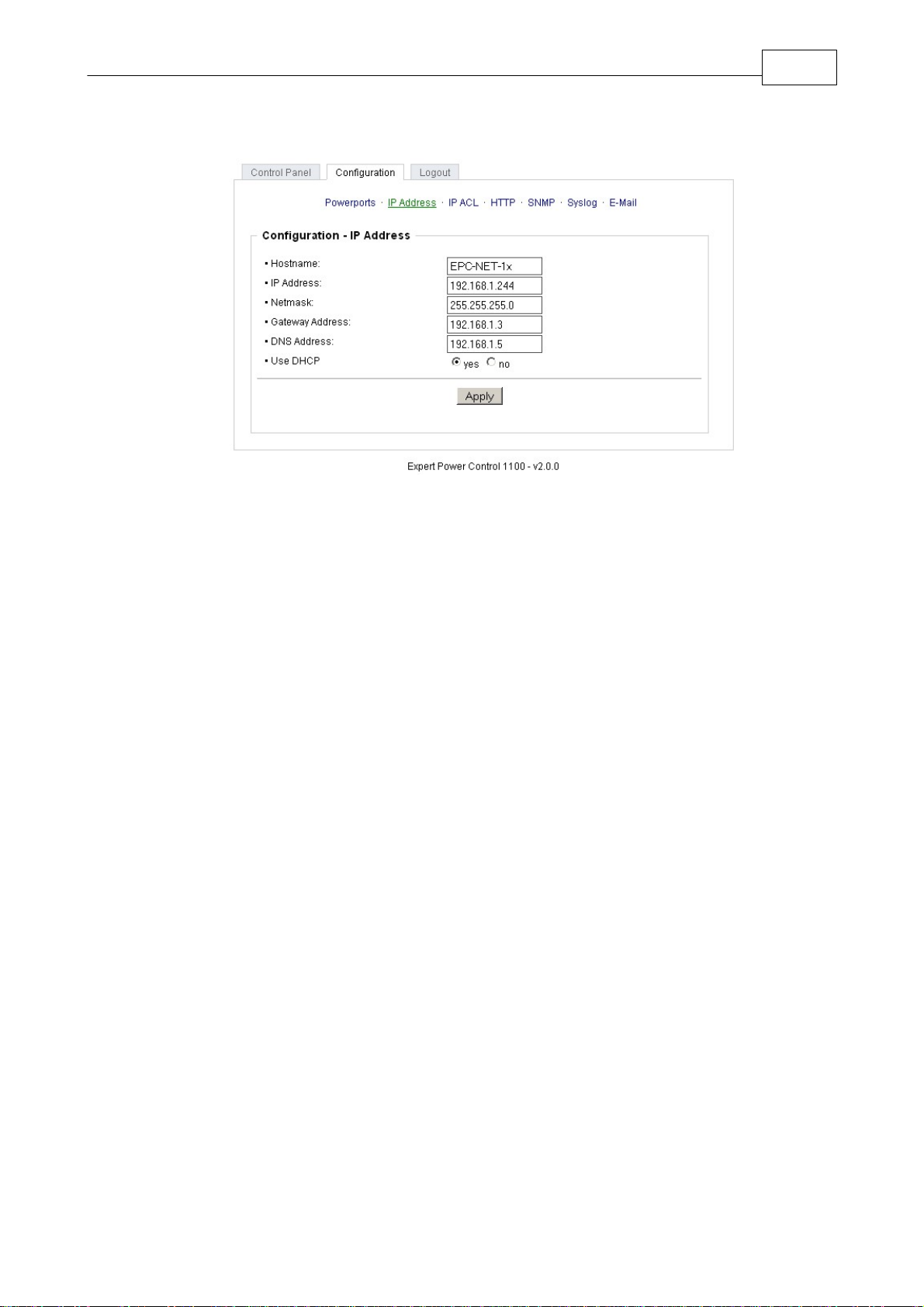
Operation and configuration are made by a webinterface. Additionally, the device can be switched directly buttons at the
housing, via SNMP or http commands, integrated in customer made applications.
An energy meter displays the energy consumption of the connected device and a lot of other electrical information. These
informations are displayed via webinterface and SNMP.
A temperature sensor or a hybrid sensor (temperature and humidity) can be connected to the Expert Power Control
1100/1101.
A watchdog function for each power port is implemented.
3 Hardware
3.1 Content of delivery
Included in delivery are:
Expert Power Control 1100/1101
Power supply cable , if Expert Power Control 1101
Quick installation guide

6
Expert Power Control 1100/1101 Hardware
3.2 Connections
1) mini DIN socket for Sensor
2) Ethernet (RJ45)
3) Button
4) Power Port (EPC 1100 CEE 7/4, max 16A/ EPC 1101 IEC C19 max.10A)
5) Power Supply (EPC 1100 CEE 7/4, 230 VAC, max.16A/ EPC 1101 IEC C20 max.10A)
6) Power Port LED
7) Status LED
3.3 Installation
1.) Connect the AC power connector on the back of the Expert Power Control 1100/1101 with a power outlet, or plug the
device into an outlet. The machine starts and is ready for operation after a short moment. The LEDs should be lit.
2) Plug the network cable into the Ethernet port on the front of the unit and connect it to your network.
3) Connect the load to the Power Port.
3.4 Status LED
The Status LED shows different states of the device:
Status LED red: Device is not connected to the Ethernet
Status LED orange: Device is connected to the Ethernet, TCP/IP settings are not allocated
Status LED green: Device is connected to the Ethernet, TCP/IP settings allocated, device is ready to use
Status LED blinks alternately red and green: Device is in Bootloader mode.

7
Expert Power Control 1100/1101 Configuration
4 Configuration
4.1 DHCP
After switch-on Expert Power Control 1100/1101 looks for a DHCP server and requests an available IP address .
Please check the IP address allocated to Expert Power Control 1100/1101 in the DHCP server settings to make sure that
the same address is used at every reboot.
4.2 Network settings with GBL_Conf
For changing the network properties manually, the program GBL_Conf.exe is required. This tool is available for free on our
website www.gude.info.
Furthermore GBL_Conf.exe enables you to install firmware updates and to reset Expert Power Control 1100/1101 to its
factory settings.
Activate bootloader mode of Expert Power Control 1100/1101 and run GBL_Conf.exe. The program will look automatically
for connected devices and will display their network configuration.
If the displayed IP address accords with the factory settings (192.168.0.2), there is either no DHCP server available in the
network or no free IP address could be allocated.
Enter a free IP address and the according netmask in the entry mask, then save these changes by clicking on Program
Device gSaveConfig.
Restart the firmware of Expert Power Control 1100/1101, so that the changes will take effect. Now click on Search in order
to have the new network configuration displayed.

8
Expert Power Control 1100/1101 Configuration
4.3 Configuration via webinterface
Go to the website of Expert Power Control 1100/1101. Enter the IP address of Expert Power Control 1100/1101 into the
address line of your internet browser:
http://”IP address of Expert Power Control 1100/1101”/
and press LOGIN.
To enter the configuration menu, click on „Configuration“ on the upper left side of the screen.
4.3.1 Configuration - Power Ports
4.3.1.1 Label
A name with a maximum of 15 characters can be entered here for each Power Port.
4.3.1.2 Initialization Status
Here can be the status of the Power Ports defined, that should be attained after the device has been turned on (remember
last state, on, off).
4.3.1.3 Initialization Delay
When the Power Port Initialization is executed after powering up of the device, a delay in the Initialization sequence can be
specified. This will prevent to turn on too much load at the same time. The delay can last up to 8191 seconds. This
corresponds to about two hours and 20 minutes.
4.3.1.4 Repower Delay
When this feature is enabled (value greater than zero), the power port will turn itself on after the specified time. This happens
after the power port was turned off via webinterface, SNMP or serial interface.

9
Expert Power Control 1100/1101 Configuration
4.3.1.5 Reset Duration
If the Reset button in the switching menu is triggered, the device will turn of the specified Power Port, wait the time entered
here (in seconds) and then it will turn on the power port again.
4.3.2 Watchdog
While using the watchdog, electrical devices can be observed. The watchdog sends ICMP-pings or TCP-pings to the device.
If these pings were not answered, during a defined delay (time or pings), the power port will reset. The watchdog function
allows to restart e.g. crashed servers or NAS systems.
You can check the watchdog function and other imformation inside of the switching menu. There are different colors:
Green text: Watchdog is active and receives ping replies
Orange text: Watchdog is activating at the moment, waiting for first ping reply
Red text: Watchdog is active and does not receive ping replies any longer
When watchdog is activating it waits of a first ping reply. During this time, the information is written as an orange text. After
the receive of the first ping reply, it switches to active, written in green letters.
When a watchdog reset a power port, the watchdog again waits for a first ping reply, as stated above.
4.3.2.1 Enable Watchdog
Here you can activate the watchdog for this power port.
4.3.2.2 Watchdog type
Here you can switch between ICMP ping or TCP ping.
4.3.2.3 Host IP
Here you can enter the IP address this watchdog should observe.
4.3.2.4 TCP Port
If TCP pings are used, here you can enter the TCP port. A TCP port is not needed, when ICMP pings are choosen.
4.3.2.5 Ping interval
Here you can enter the time between two pings.
4.3.2.6 Ping retry
Here you can enter how often the ping should be repeated, before a power port reset will be done.

10
Expert Power Control 1100/1101 Configuration
4.3.3 Configuration - IP Address
4.3.3.1 Hostname
Enter the host name of Expert Power Control 1100/1101. Expert Power Control 1100/1101 uses this name to connect with
DHCP server.
Special signs may destabilize your network.
All changes need a restart of the firmware to get valid.
4.3.3.2 IP Address
Here you can change the IP address of Expert Power Control 1100/1101.
All changes need a restart of the firmware to get valid.
4.3.3.3 Netmask
Here you can change the netmask of Expert Power Control 1100/1101.
All changes need a restart of the firmware to get valid.
4.3.3.4 Gateway
Here you can change the standard gateway of Expert Power Control 1100/1101.
All changes need a restart of the firmware to get valid.
4.3.3.5 Use DHCP
Here you can set, if Expert Power Control 1100/1101 shall get its TCP/IP settings directly from your DHCP server. If DHCP
is activated, Expert Power Control 1100/1101 proves if a DHCP server is active inside of your LAN. Then Expert Power
Control 1100/1101 requests TCP/IP settings from this server. If there is no DHCP server inside of your network, we
recommend to deactivate this function.
All changes need a restart of the firmware to get valid.

11
Expert Power Control 1100/1101 Configuration
4.3.4 Configuration - IP ACL
IP Access Control List (IP ACL) acts as an IP filter for your Expert Power Control 1100/1101. Wether it is active hosts and
subnets only can contact Expert Power Control 1100/1101, if their IP adresses are stated in this IP ACL.
e.g.: „http://192.168.0.1“ or „http://192.168.0.1/24“
If you locked yourself out by mistake, please activate the bootloader mode of Expert Power Control 1100/1101, start
Gbl_Conf.exe and deactivate IP ACL.
You can find more information about configuration of IP ACL or have a look at http://www.gude.info/wiki.
4.3.4.1 Reply ICMP-Ping requests
Here you can set, if Expert Power Control 1100/1101 shell react on pings.
4.3.4.2 Enable IP Filter
Here you can activate the IP Access Control List (IP ACL) of Expert Power Control 1100/1101.
If IP ACL is active, DHCP and SNMP only work, if all necessary servers and clients are registered in this list.
4.3.4.3 IP Access Control List
The IP Access Control List (IP ACL) is an IP filter for the Expert Power Control 1100/1101. If the filter is active, only those
hosts and subnets whose IP addresses are entered in the list, can contact the device to change settings or switch the ports.
Example:
Entry in the IP ACL
Operation
192.168.0.123
a PC with IP Address „192.168.0.123" can access to the device
192.168.0.1/24
all Devices in the Subnet „192.168.0.1/24“ can access
Sollten Sie sich hier aus Versehen „ausgesperrt“ haben, aktivieren Sie den Bootloader-Modus des Expert Power Control
1100/1101 und deaktivieren Sie mit Hilfe der GBL_Conf.exe die IP ACL.
You find possible adjustments of the IP ACL in the chapter "Configuration - IP ACL".

12
Expert Power Control 1100/1101 Configuration
4.3.5 Configuration - HTTP
4.3.5.1 HTTP Port
Here you can enter the HTTP port number, if necessary. Possible numbers are 1 ... 65534 (standard: 80). To get access to
Expert Power Control 1100/1101, you have to enter the port number behind the IP address of Expert Power Control
1100/1101, e.g.: http://192.168.0.2:1720
All changes need a restart of the firmware to get valid.
4.3.5.2 Enable HTML Auto Refresh
You can activate and de-activate the auto-refresh of the web interface. The auto-refresh keeps the information of the status
page up to date, but the additional network traffic can be unwanted.
4.3.5.3 Require HTTP Password
Password protected access can be activated here. In this case, a user and an admin password have to be defined.
Passwords have a maximum lengths of 15 characters.
Administrators are authorized to switch all ports and to modify the settings of Expert Power Control 1100/1101 and of all
ports. The username of the admin is “admin”.
Users are authorized to switch all ports but are not allowed to modify the settings of neither Expert Power Control
1100/1101 nor the ports. The username of the user is “user”.
If you have forgotten your password, activate the bootloader mode of Expert Power Control 1100/1101, start GBL-Conf.exe
and deactivate the password request.
All changes need a restart of the firmware to get valid.
4.3.5.4 Check Password on start page
If activated, the user has to enter his password, before logging in to the webinterface.

13
Expert Power Control 1100/1101 Configuration
4.3.6 Configuration - Messages
4.3.6.1 Peak measurement period
Here you can set how long the peak values of the sensors and the current measurement should be recorded.
4.3.6.2 Generate Messages
This entries control the threshold values (Min- Max values) at which alerts are send via SNMP traps, Syslog and email.
4.3.6.3 Hysteresis
A Hysteresis value prevents that too much messages are generated, when a sensor value is jittering around a sensor limit.
The following example shows the behaviour for a temperature sensor and a hysteresis value of "1". An upper limit of "50" is
set.
Example:
49.9°C - is below the upper limit
50.0°C - a message is generated for reaching the upper limit
50.1°C - is above the upper limit
...
49.1°C - is below the upper limit, but in the hysteresis range
49.0°C - is below the upper limit, but in the hysteresis range
48.9°C - a message is generated for crossing the upper limit inclusive hysteresis range
49.0°C - is below the upper limit
...

14
Expert Power Control 1100/1101 Configuration
49.9°C - is below the upper limit
50.0°C - a message is generated for reaching the upper limit
4.3.7 Configuration - SNMP
4.3.7.1 Enable SNMP-get
Here you can activate SNMP-get protocol of the Expert Power Control 1100/1101.
4.3.7.2 Community public
Here you can enter the SNMP public community.
4.3.7.3 Enable SNMP-set
Here you can activate SNMP-set protocol of the Expert Power Control 1100/1101.
4.3.7.4 Community private
Here you can enter the SNMP private community.
4.3.7.5 Download SNMP MIB
Here you can download the Expert Power Control 1100/1101 MIB table.
4.3.7.6 Enable Traps
Here you can activate SNMP-traps. if enabled, the Expert Power Control 1100/1101 will dispatch SNMP-traps to all
receivers listed.
4.3.7.7 Trap Version
Here you can choose between SNMP-traps standard v1 and v2c.
More information about the SNMP functions of the Expert Power Control 1100/1101, you can find in chapter SNMP, on
http://www.gude.info/wiki or ask our support team.

15
Expert Power Control 1100/1101 Configuration
4.3.7.8 SNMP Trap receiver
In these fields you can enter up to 8 trap receiver. A new line appears when you press the "add" button. Receiver addresses
have to be listed as follows: IP address (and, if necessary the HTTP port), e.g.: 192.168.0.2:8000.
4.3.7.9 SNMP
To get detailed status information of Expert Power Control 1100/1101 SNMP can be used. SNMP communicates via UDP
(port 161) with Expert Power Control 1100/1101: You can use SNMP to switch the power ports as
well.
Supported SNMP commands:
- SNMPGET: request status information
- SNMPGETNEXT: request the next status information
- SNMPSET: Expert Power Control 1100/1101 request change of status
You will need a Network Management System, e.g. HP-Open View, OpenNMS, Nagios etc., or the command line tools of
NET-SNMP to request information of Expert Power Control 1100/1101 via SNMP.
4.3.7.9.1 SNMP-communities
SNMP authentifies requests by so called communities.
The public community has to be added to SNMP-read-requests and the private community to SNMP write requests. You can
see the SNMP communites like read/write passwords. SNMP v1 and v2 transmit the communities without encryption.
Therefore it is simple to spy out these communities. We recommend to use a DMZ or IP ACL.
4.3.7.9.2 MIB
All information, that can be requested or changed, the so called „Managed Objects“, are descripted in „Management
Information Bases“ (MIBs).
There are three MIBs, which can be requested fromthe Expert Power Control 1100/1101:
„system“, „interface“ and „powerports“
„system“ and „interface“ are standardised MIBs (MIB-II).
„powerports“ (GUDEADS-EPC-MIB::gadsEPC) was created especially for the Expert Power Control 1100/1101.
At least, there are so called Object Identifiers (OID) subordinated to those three structures. An OID describes the location of
an information inside a MIB.
4.3.7.9.3 SNMP-traps
SNMP-Traps are system messages, sent via SNMP-protocol to different clients. On following events, Expert Power Control
1100/1101 will dispatch a SNMP-Trap:
Switching of the Power Ports
Min/Max-Alerts from the sensors
You can find more information about configuration of SNMP at http://www.gude.info/wiki.
4.3.8 Configuration - Syslog

16
Expert Power Control 1100/1101 Configuration
Syslog messages are simple text messages transmitted to a syslog server using UDP.
Linux OS regularly have a syslog daemon installed, e.g. syslog-ng. For Windows there are some freeware tools available.
On following events, Expert Power Control 1100/1101 will send a syslog message:
- Booting up
- Activation/deactivation of syslog
- Switching of Power Ports
You can find more information about configuration of Syslog in chapter Configuration - Syslog or have a look at http://www.
gude.info/wiki.
4.3.8.1 Enable Syslog
Here you can activate Syslog of Expert Power Control 1100/1101.
4.3.8.2 Syslog Server IP
If syslog is active enter here the IP address of you Syslog server.
4.3.8.3 Syslog Port
If syslog is active enter here the port number, that your Syslog server uses to receive syslog information.
More information about Syslog you can find in chapter Syslog, on http://www.gude.info/wiki or ask our support team.
4.3.9 Configuration - E-Mail
4.3.9.1 Enable E-Mail
Here you can activate the e-mail function of the device.
4.3.9.2 E-Mail server
Enter the e-mail server, e.g. mail@gmx.net
4.3.9.3 Sender address
Enter the address, the device should use, when sending e-mails.
4.3.9.4 Recipient address
Enter the e-mail address of the recipient.

17
Expert Power Control 1100/1101 Configuration
4.3.9.5 Enable Authentifiaction
If your e-mail server needs an authentification, you can enter it here.
4.3.9.6 Username
Enter the username, the device should use to log on your e-mail server.
4.3.9.7 Set new password
If your server needs a password for sending e-mails, you can enter it here.
4.3.9.8 Repeat password
Repeat the password, to enable it.
5 Operation
5.1 Switching at the device
To switch the Power Port press the button right of the RJ45 socket for 2 seconds.
You can see the state of the Power Port from the color of the (on/off) LED at the front (green = on / red = off).
5.2 Switching by Webinterface
Go to the website of Expert Power Control 1100/1101. Enter the IP address of Expert Power Control 1100/1101 into the
address line of your internet browser:
http://”IP address of Expert Power Control 1100/1101”/ and press LOGIN
5.2.1 Control Panel
In the Control Panel, you can turn on the power port directly. The exact switching functions are subsequently
described.
The Control Panel also shows the Energy Measurement values and if the sensor is connected. There you can reset the
Relative Energy counter when you press the reset button. The Total energy meter will show its values counting from the first
start.
The Min / Max values of the sensors can also be reset via the "Reset min/max" button.

18
Expert Power Control 1100/1101 Operation
5.2.1.1 Reset
By using this function, the port will be switched off. Ten seconds later, the port will switch on again, automatically.
5.2.1.2 Batchmode
The Power Port of the Expert Power Control 1100/1101 can be switched on or switched off for a selectable delay (1-30 sec.
or 1-30 min.). After the chosen delay the selected port will be switched off or switched on again automatically.
5.3 Sensor
Connect the temperature sensor with the sensor connector at the front of the device. If it is connected exactly, the recent
temperature is displayed in the login window, in the switching window and can be requested via SNMP.
The temperature sensor can be ordered as additional supplies. More information can be found at www.gude.info or requested
Temperature sensor 7001
Hybrid sensor 7002
Temperature sensor 7001
Cable length
˜ 2m
Connection
MiniDIN
Measurement
-20°C - +100°C ±2°C (max) and ±1°C (typical)
Hybrid sensor 7002
Cable length
˜ 2m
Connection
MiniDIN
Measurement
-20 - +80 Grad, ± 0,5°C / Moisture 0-100% ±3%

19
Expert Power Control 1100/1101 Operation
5.4 Energy Measurement
Electrical Measurement Specification
Category
Range
Unit
Resolution
Inaccuracy
(typical)
Voltage
110-265
V
0.01
< 1%
Current
0,1 - 16
A
0.001
< 1.5%
Frequency
45-65
Hz
0.01
< 0.03%
Phase
-180 - +180
°
0.1
< 1%
Active power
1 - 4000
W
1
< 1.5%
Reactive power
1 - 4000
Var
1
< 1.5%
Apparent power
1 - 4000
VA
1
< 1.5%
Powerfactor
0 - 1
-
0.01
< 3%
Energy Counter
Active Energy
(total)
9.999.999,999
kWh
0.001
< 3%
Active Energy
(temporary)
9.999.999,999
kWh
0.001
< 3%
6 Features
6.1 Bootloader mode
To activate the bootloader mode of Expert Power Control 1100/1101 the button must be pushed while restarting the
device. In bootloader mode it is possible to disable the password protection, to update the firmware and to restore the default
settings by running the program GBL_Conf.exe.
If the device runs already, press the buttons "select" and "ok" for three seconds. The bootloader mode of Expert Power
Control 1100/1101 is indicated by “BOOT-LDR” appended to the device name in the program window of GBL_Conf.exe.
During bootloader mode an alteration of the relais is not possible.
To restart the firmware, without toggle the Power Ports, press the buttons select and ok for three seconds again.
6.2 Firmware update
In order to update the firmware the program GBL_Conf.exe and the latest firmware are needed.
Start the device in bootloader mode and run the program GBL_Conf.exe. On the left side of the program window all Gude
devices that are in the network are listed. Select the device, that should be updated, click on Program DeviceFirmware
Update and determine the location of the new firmware.
Please note: The up-to-date firmware and GBL_Conf.exe can be found at www.gude.info, free to download.

20
Expert Power Control 1100/1101 Features
6.3 Technical information
Connections:
1 x Ethernet (RJ45)
Power Port:
1 x CEE 7/4, 230 VAC, max. 16A (1100)
or 1 x IEC C13, 230 VAC, max. 10A (1101)
Power supply inlet:
1 x CEE 7/4, 230 VAC, max. 16A (1100)
or 1 x IEC C14, 230 VAC, max. 10A (1101)
1 x Sensor Connector (mini DIN)
Network:
10/100 MBit/s 10baseT Ethernet
Protocols:
TCP/IP, HTTP, SNMP v1 and v2c, SNMP traps, Syslog, E-Mail
Switched Power (total):
10 A (~ 2000W) (1101)
16 A (~3000W) (1100)
Switched Power (per port):
10 A (~ 2000W) (1101)
16 A (~3000W) (1100)
Operating temperature:
0°C-50°C
Dimensions:
120 mm x 95 mm x 65 mm (L x H x W)
Weight:
ca.300g
6.4 Factory settings
In order to restore the default settings the device must be started in bootloader mode. Besides that the program GBL_Conf.
exe is required.
Run GBL_Conf.exe and select the device whose settings should be restored. Then click on Program Device -> Reset to Fab
default.
Please notice that all current settings will be deleted. The default settings will be loaded when the firmware of the device is
restarted the next time.
7 Support
In case of further questions, about installation or operation of the device, please have look at www.gude.info/wiki or do not
hesitate to contact our support (mail@gude.info).
8 Contact
Gude Analog- und Digitalsysteme GmbH
Eintrachtstraße 113
50668 Cologne
Germany
Phone: +49-221-912 90 97
Fax: +49-221-912 90 98
E-Mail: [email protected]
Internet: www.gude.info
Managing Director: Dr.-Ing. Michael Gude
District Court: Köln, HRB-Nr. 17 7 84
WEEE-number: DE 58173350
Value added tax identification number (VAT): DE 122778228
This manual suits for next models
1
Table of contents
Other Gude Network Hardware manuals
Popular Network Hardware manuals by other brands

Davicom
Davicom Cortex 360 quick start guide

Bosch
Bosch Rexroth NK350 manual

Idis
Idis DR-6516P-A quick start guide

M86 Security
M86 Security M86 Threat Analysis Reporter user guide

Rosenberg
Rosenberg Taurus B1 installation guide

ZyXEL Communications
ZyXEL Communications ZYWALL OTPV2 - SUPPORT NOTE V1 Support notes