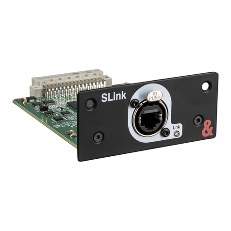
DCB 8 DBRA User manual

DCB, Inc.
2949 CR 1000 E
Dewey, Illinois
61840
217.897.6600 Tel
800.432.2638 Toll Free
217.897.1331 Fax
www.dcbnet.com
8 DBRA (Data Bridge Card) Startup and Configuration Guide
Ver 2, April, 2011
There are 2 version of the 8DBRA card, one with 2 RJ45s and 2 HD44 connectors that require 2
fanout cables, each with one D 9 and 2 DB25s. The other card has 8 RJ45 connectors. The all
RJ45 version is preferred because the connectors are all the same. The card supports transmit
data, receive data and ground on each port. RS232 control leads are not supported.
The 8DBRA card with the 8 RJ45 connectors provides easier, cleaner looking connections.
Pin outs for the RJ45 connectors:
Pin Number Signal Source
1 Signal Ground Common
3 Received Data DC (8DBRA)
5 Transmitted Data DT
7 Signal Ground Common
The 8 DBRA card supports asynchronous ports at any speed up to 19,200 bps. The speed
setting in the 8DBRA card setup screen is for reference only.
The 8DBRA card is compatible with other 8DBRA cards and any synchronous RS232 56Kbps or
64 Kbps card or 56K or 64K OCUDP from Loop or other manufacturers (tested!). The 8DBRA
card uses oversampling. See Page 16 for a description of the oversampling technique. Terminal
devices attached to non-8DBRA cards must run at the same speed as the devices attached to
the 8DBRA cards.
The 8 ports of the 8DBRA can be mapped into 3 or 4 Virtual Ports (VP). If the 8DBRA card is
configured for “NO Backup” or “1+1 Port Backup”, all 4 of the Virtual Ports are available.
Backing up the entire card in the same or a different chassis limits the card to 3 virtual ports.
Data is carried to the backup card, whether in the same chassis or to a remote site, via one of
the Virtual Ports (VP4).
Page 1

DCB, Inc.
2949 CR 1000 E
Dewey, Illinois
61840
217.897.6600 Tel
800.432.2638 Toll Free
217.897.1331 Fax
www.dcbnet.com
The 8 DBRA card has 32 time slots for each Virtual Port, for a total of 128 time slots. Any one of
the RS232 ports can be mapped to maximum of 20 downstream endpoints (DS-0s) on a
multidrop circuit.
Mapping is a 2 step process. The first step is to map the physical RS232 ports to virtual ports,
then map the virtual ports to one or more DS-0s. The card mapping is a sub menu for the card
slot. The Virtual Port mapping is done at the AM3440 system time slot interchange (TSI)
mapping level.
The 8 DBRA card protection mode allows port/card protection on the same card, on a different
card in the same chassis, or on a different (remote) chassis.
The 8DBRA card can be used at a central host site, a midpoint remote drop location, or endpoint
remote drop location.
At a host site, backup may be:
–To the backup ports (ports are paired 1 and 5, 2 and 6, 3 and 7, 4 and 8).
–To a second card in the same chassis. Card slots are paired 1&2, 3&4, 5&6, etc.
–To a second card in a different chassis at another location
At a remote drop site (downstream location), backup may be:
–To the backup ports (ports are paired 1 and 5, 2 and 6, 3 and 7, 4 and 8).
–To a second backup card in the same chassis
All 8 ports of the 8DBRA card can be mapped to different locations unless the card is set for 1+1
port backup. In 1+1 port backup, 1&5, 2&6, 3&7, 4&8 are paired, limiting the ports to 4 pairs.
The 8DBRA card can be used as a host end digital bridge device or an 8 port asynchronous data
card. The 8DBRA card is most useful, and is unique for its function as a host digital bridge
device, where data from a host computer attached to one of the RS232 host ports is broadcast
out to as many as 20 endpoints. At the card level, RS232 ports are mapped to Virtual Ports
(VPs). At the Time Slot Interchange (TSI) map level, the Virtual Port (VP) time slots are mapped
to DS-0s on T1/ 1/FOM circuits. Therefor mapping is a 2 step process.
If a card is used as an 8 port asynchronous port card only (not for its bridging capability), each
port is mapped to a different time slot on a Virtual Port. As an 8 port asynchronous card in a
point to point application, only 8 of the 128 time slots are used. Only one Virtual Port (VP) needs
to be used.
Page 2

DCB, Inc.
2949 CR 1000 E
Dewey, Illinois
61840
217.897.6600 Tel
800.432.2638 Toll Free
217.897.1331 Fax
www.dcbnet.com
Step One, setting up t e card mode for 56 Kbps or 64 Kbps operation:
The 8DBRA card can be set to over sample at either 56 Kbps or 64 Kbps. All 8 ports share the
same sampling rate of either 56 Kbps or 64 Kbps. After the card is changed from one rate to the
other, it is necessary to reset the card.
When the 8DBRA card is reset, all card mapping is set to default (no mapping). The card reset
takes about 50 seconds to complete. Be patient.
Below are the screens showing the “M Mode Setup” selection, the 56/64K selection.→
SLOT 5 8DBRA P1 === Port Menu === 13:51:15 04/03/2011
Version : SW V1 02 01 03/31/2011
HW Ver B FPGA Ver B
Backup Mode: NO (64K)
[DISPLAY] [SETUP]
T -> Port Map Configuration M -> Mode Setup
C -> RS232 Configuration B -> Backup Setup
K -> Port Map Setup
S -> RS232 Config Setup
G -> Upgrade Firmware
SLOT 5 8DBRA P1 === Mode Setup === 13:51:30 04/03/2011
ARROW KEYS: CURSOR MOVE, TAB: ROLL OPTIONS
Mode: 64K
Note: Change Mode will reset card
Card reset celars all 8DBRA card mapping (8DBRA ports and time slots to Virtual Ports). The
reset process takes a bit less than one minute.
Page 3

DCB, Inc.
2949 CR 1000 E
Dewey, Illinois
61840
217.897.6600 Tel
800.432.2638 Toll Free
217.897.1331 Fax
www.dcbnet.com
Simple Application of t e 8DBRA, single ost location only:
First, note that the chassis has 8DBRA cards in slots 3 and 4.
LOOP AM3440-C === Information Summary === 11:54:00
12/01/2010
Slot Card/Interface Serial Software Version Registered Card
==== ================ ====== =================== ===============
A FOM N/A FOM
B
C
D
==== ================ ====== =================== ===============
1 Quad T1 002095 V3 02 03 07/30/2010 Quad T1
2 E&M 001937 V4 02 02 07/30/2010 E&M
3 8DB A N/A V1.01.01 05/05/2010 8DB A
4 8DB A N/A V1.01.01 05/05/2010 8DB A
5 FXS 002097 V3 01 03 07/30/2010 FXS
Next, select a card. From the main menu, “U” and “3” for slot 3. No backup mode selected
yet.
SLOT 3 8DBRA P1 === Port Menu === 11:57:44 12/01/2010
Version : SW V1 01 01 05/05/2010
HW Ver B FPGA Ver A
Backup Mode: NO
[DISPLAY] [SETUP]
T -> Port Map Configuration B -> Backup Setup
C -> RS232 Configuration K -> Port Map Setup
S -> RS232 Config Setup
L -> Loopback Test
Page 4

DCB, Inc.
2949 CR 1000 E
Dewey, Illinois
61840
217.897.6600 Tel
800.432.2638 Toll Free
217.897.1331 Fax
www.dcbnet.com
G -> Upgrade Firmware
Select “B - > Backup Setup” Select “1+1 Port Backup”. This selection pairs ports 1 & 5, 2 & 6,
3 & 7, 4 & 8. They are digitally bridged together.
SLOT 3 8DBRA P1 === Backup Setup === 12:01:19 12/01/2010
ARROW KEYS: CURSOR MOVE, TAB: ROLL OPTIONS
Backup Type : 1+1 Port Backup
Warning!! Change Backup Type will clear map
Next you can select “S - > RS232 Config Setup”. This is reference only. The card supports any
async speed up to 19200 bps regardless of what is on this screen.
SLOT 3 8DBRA P1 === RS232 Setup === 12:04:25 12/01/2010
ARROW KEYS: CURSOR MOVE, TAB: ROLL OPTIONS
ATE : 9.6KBps
Interface : 8RJ
Back out to the Port Menu and select “K - > Port Map Setup” See the port map setup on the
next page. You will need to map only ports 1, 2, 3 and 4.
In the example below, RS232 (the physical port) is mapped to time slots 1, 2 and 3 of Virtual Port
1. This will allow the data from RS232 port 1 to be mapped to 3 different DS-0s. Use the arrow
keys to move down the screen from Virtual Port, to TS start, to Total TS, RS232 Port and
Command. When you get down to “Command : Set”, use the “ nter” key to accept the
selection. Using the arrow key does not accept the mapping.
Page 5

DCB, Inc.
2949 CR 1000 E
Dewey, Illinois
61840
217.897.6600 Tel
800.432.2638 Toll Free
217.897.1331 Fax
www.dcbnet.com
SLOT 3 8DBRA P3 === Port Map Setup === 13:31:19 12/01/2010
ARROW KEYS: CURSOR MOVE, TAB: ROLL OPTIONS
[Setup]
Virtual Port: P1
TS start : 01
Total TS : 01
RS232 Port : 1
Command : Set
[Display]
Port TS: 1 9 17 25 32
VP1 MAP: 111iiiii iiiiiiii iiiiiiii iiiiiiii
VP2 MAP: iiiiiiii iiiiiiii iiiiiiii iiiiiiii
VP3 MAP: iiiiiiii iiiiiiii iiiiiiii iiiiiiii
VP4 MAP: iiiiiiii iiiiiiii iiiiiiii iiiiiiii
Note: i=idle, 1~8=RS232 port number
After the RS232 ports are mapped to the Virtual Ports, back out to the Main Controller Menu,
then select “S - > System Setup” and “C - > TSI Map Setup”. Map the Virtual Ports to the
appropriate DS-0s.
In the example below, Virtual Port 1 of the 8DBRA in slot 3 is mapped to DS-0 number 1 on 3
different T1 circuits on the Slot 1 Quad T1 card. PO is the port, TS the time slot, SL is the slot
number. Immediately below is a snapshot of the key data from the TSI mapping page.
8DBRA Quad T1
================
PO/TS D SL/PO TS
1 1 d 1 1 1
1 2 d 1 2 1
1 3 d 1 3 1
When mapping the System Time Slot Interchange (TSI), you are always mapping 8DBRA virtual
ports. The first column above labeled “PO” under 8DBRA is the Virtual Port number. RS232
ports were previously mapped to the virtual ports using the card slot sub menu. See the top of
this page.
Page 6

DCB, Inc.
2949 CR 1000 E
Dewey, Illinois
61840
217.897.6600 Tel
800.432.2638 Toll Free
217.897.1331 Fax
www.dcbnet.com
The full DS-0 TSI mapping page is shown below:
LOOP AM3440-C === System Setup (MAP) === 13:47:09 12/01/2010
ARROW KEYS: CURSOR MOVE, TAB: ROLL OPTIONS
MAP NO: MAP_1
Target 8BDRA Source
Target PO/TS D SL/PO TS PO/TS D SL/PO TS PO/TS D SL/PO TS PO/TS D SL/PO TS
Slot : 3 ===== ========== ===== ========== ===== ========== ===== ==========
Port : 1 1 d 1 1 1 17 d
T S : 01 1 2 d 1 2 1 18 d
1 3 d 1 3 1 19 d
4 d 20 d
T S # : 1 5 d 21 d
Clear : No 6 d 22 d
d/v : d 7 d 23 d
8 d 24 d
9 d 25 d
Source 10 d 26 d
Slot : A 11 d 27 d
Port : 12 d 28 d
T S : 01 13 d 29 d
14 d 30 d
Confirm?Yes 15 d 31 d
16 d 32 d
Since 1+1 Port Backup was selected, host ports 1 & 5, 2 & 6, 3& 7, 4 & 8 are bridged. Host data
transmitted into either port and is received downstream via the Virtual Port time slots mapped to
the T1 DS-0s. Remote terminal responses are received on both of the paired ports.
In summary, follow these steps:
1. Select the backup type.
2. Map RS232 ports to the Virtual Ports through the card slot sub menu.
3. Map the Virtual Ports to the T1/ 1/FOM time slots on the System Setup TSI Map Setup.
Page 7

DCB, Inc.
2949 CR 1000 E
Dewey, Illinois
61840
217.897.6600 Tel
800.432.2638 Toll Free
217.897.1331 Fax
www.dcbnet.com
Mid point 8DBRA wit local RTU and data passed downstream:
The host is presumed to be mapped per the first example on pages 2 through 6. The midpoint
AM3440 will have an 8DBRA card and a Quad T1 card. We want to do the following:
Set the 8DBRA card for 1+1 Port Backup
On the 8DBRA Port Map Setup, map RS232 port 1 to the upstream host T1 to the AM3440.
On the 8DBRA Port Map Setup, map RS232 port 2 to the downstream T1 to the V4200
SLOT 3 8DBRA P1 === Backup Setup === 14:13:33 12/01/2010
ARROW KEYS: CURSOR MOVE, TAB: ROLL OPTIONS
Backup Type : 1+1 Port Backup
SLOT 3 8DBRA P1 === Port Map Setup === 14:14:01 12/01/2010
ARROW KEYS: CURSOR MOVE, TAB: ROLL OPTIONS
[Setup]
Virtual Port: P1
TS start : 01
Total TS : 01
RS232 Port : 1
Command : Set
[Display]
Port TS: 1 9 17 25 32
VP1 MAP: 1iiiiiii iiiiiiii iiiiiiii iiiiiiii
VP2 MAP: 2iiiiiii iiiiiiii iiiiiiii iiiiiiii
VP3 MAP: iiiiiiii iiiiiiii iiiiiiii iiiiiiii
VP4 MAP: iiiiiiii iiiiiiii iiiiiiii iiiiiiii
Two different Virtual Ports (VP1 and VP2) are used in the above example. VP1 only could have
been used, with RS232 port 1 mapped to VP1, Time Slot 1, and RS232 port 2 mapped to VP1,
Time Slot 2.
Page 8

DCB, Inc.
2949 CR 1000 E
Dewey, Illinois
61840
217.897.6600 Tel
800.432.2638 Toll Free
217.897.1331 Fax
www.dcbnet.com
The screen below shows that the 8DBRA RS232 Port 1 is mapped to Virtual Port 1, and VP 1 is
mapped to the Slot 1 Port 1 DS-0 number 1, which is a Quad T1 card. This time slot goes
upstream toward the host.
LOOP AM3440-C === System Configuration (Map) === 14:18:05 12/01/2010
ARROW KEYS: CURSOR MOVE, TAB: ROLL OPTIONS
Map Number:MAP_1
Slot Number: 3 8BDRA PO/TS D SL/PO TS PO/TS D SL/PO TS
Port Number:VP1 ===== ========== ===== ==========
1 1 d 1 1 1 17 d
2 d 18 d
3 d 19 d
The screen below shows that the 8DBRA RS232 Port 2 is mapped to Virtual Port 2, and VP 2 is
mapped to the Slot 1 Port 2 DS-0 number 1, which is a Quad T1 card. This time slot goes
downstream toward the V4200.
LOOP AM3440-C === System Configuration (Map) === 14:18:05 12/01/2010
ARROW KEYS: CURSOR MOVE, TAB: ROLL OPTIONS
Map Number:MAP_1
Slot Number: 3 8BDRA PO/TS D SL/PO TS PO/TS D SL/PO TS
Port Number:VP2 ===== ========== ===== ==========
2 1 d 1 2 1 17 d
2 d 18 d
3 d 19 d
Data from the host comes out RS232 Ports 1 and 5 because of the 1+1 Port Backup. RS232
Port 1 can be connected to a local RTU. To get data downstream, connect RS232 Port 5 to
RS232 Port 2 or 6 with a 3-wire RJ45 to RJ45 crossover cable. See the table on page 1 for
pinouts. Connect the ground 1 to 1 or 7 to 7. Connect 3 to 5 and 5 to 3 to cross the data leads.
Page 9

DCB, Inc.
2949 CR 1000 E
Dewey, Illinois
61840
217.897.6600 Tel
800.432.2638 Toll Free
217.897.1331 Fax
www.dcbnet.com
SCADA Dual Primary and Secondary Backup Host:
First, set the Backup on the Primary Host of a Dual Host system.
SLOT 3 8DBRA P1 === Backup Setup === 16:36:29 12/01/2010
ARROW KEYS: CURSOR MOVE, TAB: ROLL OPTIONS
Backup Type : Dual Host
Site : Primary
Map the RS232 ports to the Virtual Ports. There are 3 Virtual Ports available. VP4 is used to map
the card to the Secondary backup site.
Page 10

DCB, Inc.
2949 CR 1000 E
Dewey, Illinois
61840
217.897.6600 Tel
800.432.2638 Toll Free
217.897.1331 Fax
www.dcbnet.com
In the example below, RS232 ports 1 and 2 each have 2 time slots mapped. RS232 Port 1 is
mapped to VP1, RS232 Port 2 is mapped to VP2. Alternatively, both RS232 ports could be
mapped to VP1, where RS232 Port 1 uses VP1, Time Slots 1 and 2, RS232 Port 2 could use VP1,
Time Slots 3 and 4 (or any other, but consecutive time slots are easier to track.
SLOT 3 8DBRA P1 === Port Map Setup === 16:38:15 12/01/2010
ARROW KEYS: CURSOR MOVE, TAB: ROLL OPTIONS
[Setup]
Virtual Port: P1
TS start : 01
Total TS : 01
RS232 Port : 1
Command : Set
[Display]
Port TS: 1 9 17 25 32
VP1 MAP: 11iiiiii iiiiiiii iiiiiiii iiiiiiii
VP2 MAP: 22iiiiii iiiiiiii iiiiiiii iiiiiiii
VP3 MAP: iiiiiiii iiiiiiii iiiiiiii iiiiiiii
Note: i=idle, 1~8=RS232 port number
Map the Virtual Ports VP1 and VP2 shown above to the appropriate T1 DS-0s that go out to the
remote locations. The map below has VP1 mapped to the Quad T1 Port 1, time slots 1 and 2.
LOOP AM3440-C === System Setup (MAP) === 16:48:13 12/01/2010
ARROW KEYS: CURSOR MOVE, TAB: ROLL OPTIONS
MAP NO: MAP_1
Target 8BDRA Source
Target PO/TS D SL/PO TS PO/TS D SL/PO TS PO/TS D SL/PO TS PO/TS D SL/PO TS
Slot : 3 ===== ========== ===== ========== ===== ========== ===== ==========
Port : 1 1 d 1 1 1 17 d
T S : 01 1 2 d 1 1 2 18 d
3 d 19 d
4 d 20 d
T S # : 1 5 d 21 d
Clear : No 6 d 22 d
d/v : d 7 d 23 d
8 d 24 d
9 d 25 d
Source 10 d 26 d
Slot : 1 11 d 27 d
Port : P1 12 d 28 d
T S : 01 13 d 29 d
14 d 30 d
Confirm?Yes 15 d 31 d
16 d 32 d
<< Press ESC to return to Controller Setup menu, then Press D to active >>
Page 11

DCB, Inc.
2949 CR 1000 E
Dewey, Illinois
61840
217.897.6600 Tel
800.432.2638 Toll Free
217.897.1331 Fax
www.dcbnet.com
Map the Virtual Port 4 to the T1 that connects to the Secondary Backup site. The example below
shows 2 DS-0s mapped over a T1 to the backup site. The 2 DS-0s are necessary because there
are 2 Virtual Ports used on the 8DBRA Primary Site card that are also directed to the Secondary
backup site. ach DS-0 on VP4 carries a separate asynchronous polling data stream.
LOOP AM3440-C === System Setup (MAP) === 16:49:13 12/01/2010
ARROW KEYS: CURSOR MOVE, TAB: ROLL OPTIONS
MAP NO: MAP_1
Target 8BDRA Source FOM CAS
Target PO/TS D SL/PO TS PO/TS D SL/PO TS PO/TS D SL/PO TS PO/TS D SL/PO TS
Slot : 3 ===== ========== ===== ========== ===== ========== ===== ==========
Port : VP4 4 1 d 1 3 1 17 d 1 d 17 d
T S : 01 4 2 d 1 3 2 18 d 2 d 18 d
3 d 19 d 3 d 19 d
4 d 20 d 4 d 20 d
T S # : 1 5 d 21 d 5 d 21 d
Clear : No 6 d 22 d 6 d 22 d
d/v : d 7 d 23 d 7 d 23 d
8 d 24 d 8 d 24 d
9 d 25 d 9 d 25 d
Source 10 d 26 d 10 d 26 d
Slot : A 11 d 27 d 11 d 27 d
Port : P1 12 d 28 d 12 d 28 d
T S : 01 13 d 29 d 13 d 29 d
14 d 30 d 14 d 30 d
Confirm?Yes 15 d 31 d 15 d 31 d
16 d 32 d 16 s
<< Press ESC to return to Controller Setup menu, then Press D to active >>
Set up the backup mode in the Secondary backup site 8DBRA card.
SLOT 4 8DBRA P1 === Backup Setup === 17:09:12 12/01/2010
ARROW KEYS: CURSOR MOVE, TAB: ROLL OPTIONS
Backup Type : Dual Host
Site : Secondary
It is not necessary to map any ports at the Secondary backup site.
SLOT 4 8DBRA P1 === Port Map Setup === 17:10:57 12/01/2010
This is Secondary site of Dual Host, don't need set map!
[Display]
Port TS: 1 9 17 25 32
VP4 MAP: 12345678
Page 12

DCB, Inc.
2949 CR 1000 E
Dewey, Illinois
61840
217.897.6600 Tel
800.432.2638 Toll Free
217.897.1331 Fax
www.dcbnet.com
At the Secondary backup site, map the incoming T1 DS-0 time slots to the 8DBRA Virtual Port 4.
VP4 is the only port you can chose when mapping to a card set to be the Dual Host Secondary.
LOOP AM3440-C === System Setup (MAP) === 17:14:15 12/01/2010
Please Input decimal number (1~32), BACKSPACE to edit
MAP NO: MAP_1
Target 8BDRA Source
Target PO/TS D SL/PO TS PO/TS D SL/PO TS PO/TS D SL/PO TS PO/TS D SL/PO TS
Slot : 4 ===== ========== ===== ========== ===== ========== ===== ==========
Port : VP4 4 1 d 1 4 1 17 d
T S : 01 4 2 d 1 4 2 18 d
3 d 19 d
4 d 20 d
T S # : 1 5 d 21 d
Clear : No 6 d 22 d
d/v : d 7 d 23 d
8 d 24 d
9 d 25 d
Source 10 d 26 d
Slot : A 11 d 27 d
Port : 12 d 28 d
T S : 01 13 d 29 d
14 d 30 d
Confirm?Yes 15 d 31 d
16 d 32 d
Page 13

DCB, Inc.
2949 CR 1000 E
Dewey, Illinois
61840
217.897.6600 Tel
800.432.2638 Toll Free
217.897.1331 Fax
www.dcbnet.com
1+1 Card Backup
Backup cards are in adjacent slots, such as 1 & 2, 3 & 4, 5 & 6, 7 & 8, 9 & 10. The odd
numbered slot is primary, the even numbered slot is the backup.
First set the back up mode in both cards.
SLOT 3 8DB A P1 === Backup Setup === 17:31:56 12/01/2010
ARROW KEYS: CURSOR MOVE, TAB: ROLL OPTIONS
Backup Type : 1+1 Card Backup
Mode : revertible
Force Switch: NO
Status : Working
SLOT 4 8DB A P1 === Backup Setup === 17:32:50 12/01/2010
ARROW KEYS: CURSOR MOVE, TAB: ROLL OPTIONS
Backup Type : 1+1 Card Backup
Mode : revertible
Force Switch: NO
Status : Stand-By
Page 14

DCB, Inc.
2949 CR 1000 E
Dewey, Illinois
61840
217.897.6600 Tel
800.432.2638 Toll Free
217.897.1331 Fax
www.dcbnet.com
Now map the odd numbered card. The map is automatically propagated to the second card.
SLOT 3 8DBRA P1 === Port Map Setup === 17:47:32 12/01/2010
ARROW KEYS: CURSOR MOVE, TAB: ROLL OPTIONS
[Setup]
Virtual Port: P1
TS start : 03
Total TS : 01
RS232 Port : 1
Command : Set
[Display]
Port TS: 1 9 17 25 32
VP1 MAP: 11iiiiii iiiiiiii iiiiiiii iiiiiiii
VP2 MAP: 22iiiiii iiiiiiii iiiiiiii iiiiiiii
VP3 MAP: iiiiiiii iiiiiiii iiiiiiii iiiiiiii
Map the Virtual Ports to the DS-0 time slots as described previously in this document. Now the
same port number in either card can be connect to a polling host. Polls from either host are
broadcast out to the remote drop locations. All poll responses from remote locations come out
the same RS232 port number to the polling host on both cards.
Page 15

DCB, Inc.
2949 CR 1000 E
Dewey, Illinois
61840
217.897.6600 Tel
800.432.2638 Toll Free
217.897.1331 Fax
www.dcbnet.com
8DBRA card used as an 8 port async ronous card
Set the card for “Backup Type: NO”
SLOT 3 8DBRA P1 === Backup Setup === 18:14:18 12/01/2010
ARROW KEYS: CURSOR MOVE, TAB: ROLL OPTIONS
Backup Type : NO
Map port 1 through 8 to VP1 using the “K - > Port Map Setup”.
SLOT 3 8DBRA P1 === Port Map Setup === 18:15:56 12/01/2010
ARROW KEYS: CURSOR MOVE, TAB: ROLL OPTIONS
[Setup]
Virtual Port: P1
TS start : 01
Total TS : 01
RS232 Port : 1
Command : Set
[Display]
Port TS: 1 9 17 25 32
VP1 MAP: 12345678 iiiiiiii iiiiiiii iiiiiiii
VP2 MAP: iiiiiiii iiiiiiii iiiiiiii iiiiiiii
VP3 MAP: iiiiiiii iiiiiiii iiiiiiii iiiiiiii
VP4 MAP: iiiiiiii iiiiiiii iiiiiiii iiiiiiii
Map the VP1 time slots 1 through 8 to whatever DS-0 time slots required.
LOOP AM3440-C === System Setup (MAP) === 18:17:05 12/01/2010
Please Input decimal number (1~24), BACKSPACE to edit
MAP NO: MAP_1
Target 8BDRA Source Quad-T1 CAS
Target PO/TS D SL/PO TS PO/TS D SL/PO TS PO/TS D SL/PO TS PO/TS D SL/PO TS
Slot : 3 ===== ========== ===== ========== ===== ========== ===== ==========
Port : VP1 1 1 d 1 1 1 17 d 1 1 d 3 1 1 17 d
T S : 08 1 2 d 1 1 2 18 d 1 2 d 3 1 2 18 d
1 3 d 1 1 3 19 d 1 3 d 3 1 3 19 d
1 4 d 1 1 4 20 d 1 4 d 3 1 4 20 d
T S # : 01 1 5 d 1 1 5 21 d 1 5 d 3 1 5 21 d
Clear : No 1 6 d 1 1 6 22 d 1 6 d 3 1 6 22 d
d/v : d 1 7 d 1 1 7 23 d 1 7 d 3 1 7 23 d
1 8 d 1 1 8 24 d 1 8 d 3 1 8 24 d
9 d 25 d 9 d
Source 10 d 26 d 10 d
Slot : 1 11 d 27 d 11 d
Port : P1 12 d 28 d 12 d
T S : 08 13 d 29 d 13 d
Page 16

DCB, Inc.
2949 CR 1000 E
Dewey, Illinois
61840
217.897.6600 Tel
800.432.2638 Toll Free
217.897.1331 Fax
www.dcbnet.com
Async ronous Data Over Sync ronous Links Using Oversampling
Any synchronous bit stream RS232 interface can transport asynchronous data that is 1/3 or less
the synchronous data rate. For example, 2400 async data can be sent over a 9600 bps
synchronous link. Data running async 9600 can be sent over a synchronous 56 or 64 kbps link.
Data at 19200 bps is right at the borderline with 56 kbps links, but will typically work reliably.
Likewise, 38,400 bps async data can be sent over a synchronous link of 192 kbps or 256 kbs.
While 1/3 may be sufficient, it is preferable to have a synchronous sample rate that is at least 4
times faster than the asynchronous data rate.
The key is that the synchronous channel is fast enough so the bit width of the async data is the
1/3 or less the sync bit width. The async bit width can be distorted and shift back and forth (jitter)
as long as the sync sampling is fast enough.
Async UARTS will sample async data at a rate 16 times the async bits per second rate. A UART
sets or resets its sampling starting point whenever there is a data transition between a one to a
zero (mark to space). The async UART then counts over 8 sample times to the middle of the
data bit transition data, where each count, or sample, is 1/16th of the async bit time. At the 8th
sample, the UART makes the decision if the bit is a one or is a zero.
With asynchronous characters, typically 8 data bits plus a start bit and a stop bit, the UART is
guaranteed that there is a zero at least every 10 bits, since every start bit of a character is a
start/space/zero bit that follows a stop/mark/one bit.
How over sampling works is illustrated below with underscore and dash, where the underscore
represents a one, the dash a zero. The sync sample is a “+” , the async sample is “|”:
Async Bit: ___----------------____
Sync sample Rate: + + + + + +
Async UART sample Rate:|||||||||||||||||||||||||||||
The above shows that both the sync data channel and the async UART use sampling. The sync
channel sampling of the async data mimics the function of the standard async UART, but with a
lower sample rate. While the sample rate is lower, the async one and zero data bits are sampled
fast enough to allow the sync channel to replicate the data over the communications link.
Page 17
Table of contents
Other DCB Network Hardware manuals
Popular Network Hardware manuals by other brands
Vivotek
Vivotek ND8301 Quick installation guide
GIGA
GIGA G4200C Quick installation guide

Cambium Networks
Cambium Networks ePMP Elevate quick start guide
Rockwell Automation
Rockwell Automation Allen-Bradley 1756-EN2F user manual
Cisco
Cisco LightStream 1010 Hardware installation guide
H3C
H3C SecPath L1000-A installation guide
Ingrasys
Ingrasys nastorage 4600 series user manual
BreezeCOM
BreezeCOM BreezeACCESS MMDS Series Installation guides
Zhone
Zhone 6211 Quick installation instructions

Helwett Packard
Helwett Packard FF 12904E Product End-of-Life Disassembly Instructions
Vega Absolute
Vega Absolute SI-13 user manual
ESD electronic
ESD electronic CAN-PCI/266 Hardware installation and technical data
