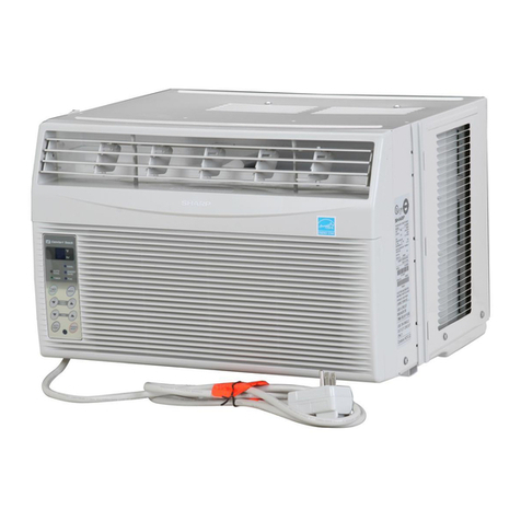
Sharp AF-S80CX User manual

1
AF-S80CX
S3212AFS08CX/
SERVICE MANUAL
Page
SPECIFICATIONS ................................................................................................................................................ 2
EXTERNAL DIMENSIONS ................................................................................................................................... 4
HOW TO OPERATE ............................................................................................................................................. 5
INSTALLATIOIN INSTRUCTIONS ......................................................................................................................13
DISASSEMBLING PROCEDURE....................................................................................................................... 16
HOW TO REPAIR REFRIGERATION .................................................................................................................19
ELECTRICAL COMPONENT TEST ....................................................................................................................21
MICROCOMPUTER CONTROL SYSTEM ..........................................................................................................22
TROUBLESHOOTING GUIDE ............................................................................................................................26
COOLING LOAD ESTIMATE FORM ...................................................................................................................31
RUNNING CONDITION .......................................................................................................................................33
PACKING AND ACCESSORIES .........................................................................................................................34
REPLACEMENT PARTS LIST ............................................................................................................................35
TABLE OF CONTENTS
AIR CONDITIONER
MODEL
Intheinterestsofuser-safety(Requiredbysafetyregulationsinsome
countries)thesetshouldberestoredtoitsoriginalconditionandonly
parts identical to those specified should be used.
AF-S80CX
SHARP CORPORATION This document has been published to be used for after
sales service only.
The contents are subject to change without notice.

2
AF-S80CX
SPECIFICATIONS
Models AF-S80CX
Cooling capacity BTU/h 8000
Moisture removal Pints/h 2.3
ELECTRICAL DATA
Phase Single
Rared frequency Hz 60
Rated voltage Volts 115
Rated current Amps 6.7
Rated input Watts 730
Power factor % 95
EER BTU/Wh 11.0
COMPRESSOR
Type (Hermetically sealed rotary type)
Model, Motor output 2R12T126A-6A, 550W
REFRIGERANT SYSTEM
Evaporator Louver fin, Grooved tube, 7mm, Hair pin
Condenser Louver fin, Grooved tube, 7mm, Hair pin
Control O.D. x I.D. x Length x Q'ty(mm) 2.7 x 1.0 x 800 x 2
(Capillary tube)
Refrigerant volume R-22(OZ) 15.5
(Factory change)
NET DIMENSIONS
Width Height Depth
inches(mm)
19-11/16(500) x 14-9/16(370) x 17-3/32(434)
Net Weight lbs 53
GROSS DIMENSIONS
Width Height Depth
inches(mm)
22-27/32(580) x 18-5/16(465) x 19-31/32(507)
Gross Weight lbs 60
FAN SYSTEM
Indoor side(Evaporator) Centrifugal fan
Outdoor side(Condenser) Propeller fan
Air flow rate(indoor side) CFM High / Med / Low
187 / 173 / 155
OTHERS
Safety devices Compressor: Overload relay
Fan motor: Internal thermal protector
Air filter Polypropylene net
Power cord length ft 6.0
Power plug type 125V, 10A

3
AF-S80CX
ELECTRICAL PARTS
Models
AF-S80
CX
Running capacitor 250V-35µF
Fan capacitor 250V-6µF
Thermistor 15kΩat 78˚F
Fan motor OBM-2508K1 (MLB003)
Overload relay MRA98706
WIRING DIAGRAM
Figure W-1
GR
OVERLOAD
PROTECTOR
A.C
EARTH
M.C
CONNECTOR
HML
FAN MOTOR
CAPACITOR
250V 6µF
FAN MOTOR
RUNNING
CAPACITOR
250V 35µF
THERMAL
PROTECTOR
BL
BL
BLBK
BK
BK
GY RE OR WH
COMPRESSOR
MOTOR
BK
BL
RE
WH
GR
GY
OR
: BLACK
: BLUE
: RED
: WHITE
: GREEN
: GRAY
: ORANGE
POWER SUPPLY CORD
115V 60Hz
3A 125V
IN
GR MRY CONTROL
BOARD UNIT
NR C1
CN1
BCN2
BCN3
TR
OUT
RIBBED
NON RIBBED
BK
BK
C
R
RE WH
GY
BCN1
CN2
CN3
WH
OR
RE
GY
S
FU1
123654
WIRE COLOR
YELLOW TH1
RY3
RY2
RY1
CNR3
CNR2
CNR1
THERMISTOR
(ROOM TEMP)
8
7
1
3
5
DISPLAY
BOARD
UNIT

4
AF-S80CX
EXTERNAL DIMENSIONS
19-11/16"
35-7/16" (full opened)
23-5/8" (full closed)
17-3/32"
13-5/8"
1-15/32"
15-11/16"
4-15/32"
Fig. E-1

5
AF-S80CX
PARTS NAMES
UNIT
CONTROL PANEL
1Front Cabinet
2Air Inlet (Indoor Side)
3Horizontal Louvers
4Vertical Louvers
5Air Outlet (Indoor Side)
6Control Panel
7Rear Cabinet
8Air Inlet (Outdoor side)
9Filter (Pull the filter handle
to the right to remove.)
0Filter Handle
qPower Cord
1Receiver window for remote control signal
2Display
3SELECTOR indicator
4SELECTOR pad
5TEMPERATURE setting pad
----Lower temp. ----Raise temp.
6TIMER ON/OFF pad
7TIMER indicator
8ENERGY SAVER pad
9ENERGY SAVER indicator
0POWER ON/OFF pad
qPOWER indicator
POWER
ON/OFF
F
hr
SELECTOR
TIMER
ON/OFF
ENERGY
SAVER
COOL / FAN TEMP
12
10
3
4 5 6 7 9
8
11
34567
8
9
10
11
1
2
HOW TO OPERATE

6
AF-S80CX
NOTE:
•The latest temperature setting will be memorized and will appear on the display the next time
the unit is turned on.
•In cases of power outages or when the unit is disconnected; when the power is restored or the
unit is plugged in, the unit and display will return to the preset conditions of 74°F and HIGH
COOL. The unit will not automatically turn back on. The user must touch POWER ON/OFF to
resume opertion.
---Lower temp.
---Raise temp.
Touch POWER ON/OFF pad.
•The unit is preset at 74°F and HIGH
COOL. This will show in the display
when the power is first turned on.
•POWER indicator and SELECTOR
indicator (COOL) will light.
Toturnofftheunit,touchPOWER
ON/OFF pad again.
•POWER indicator and SELECTOR
indicator will go off.
Touch the TEMPERATURE setting
pad to adjust the temperature
setting.
•Temperature can be set within the range
of 64°F to 86°F.
•Display will change as you touch
the pad.
2
1
During cooling operation
COOLING OPERATION
TO CHANGETEMPERATURE SETTING
POWER
ON/OFF
F
hr
SELECTOR
TIMER
ON/OFF
ENERGY
SAVER
COOL / FAN TEMP
POWER
indicatorSELECTOR indicator
POWER ON/OFF pad
POWER
ON/OFF
F
hr
SELECTOR
TIMER
ON/OFF
ENERGY
SAVER
COOL / FAN TEMP
TEMPERATURE setting pad

7
AF-S80CX
POWER
ON/OFF
F
hr
SELECTOR
TIMER
ON/OFF
ENERGY
SAVER
COOL / FAN TEMP
SELECTOR indicator
SELECTOR pad
TO CHANGE FAN SPEED AND OPERATION MODE
During operation
TouchSELECTORpadandselectthe
operation mode and fan speed.
•SELECTORindicatoranddisplaywilllight
in order as you touch.
NOTES ON OPERATION MODE:
SELECTOR DISPLAY
HIGH COOL
MED COOL
LOW COOL
HIGH FAN
MED FAN
LOW FAN
•The latest operation mode will be memorized and the selector indicator and display will light
when the unit is turned on.
•In fan only operation, the temperature display will go off.
•When the SELECTOR is changed to fan only operation from cooling operation, it will take 5
seconds for the compressor to stop.
COOL
COOL
COOL
FAN
FAN
FAN
MODE
Cooling operation with high fan speed.
Cooling operation with medium fan speed.
Cooling operation with low fan speed.
Fan only operation with high fan speed.
Fan only operation with medium fan speed.
Fan only operation with low fan speed.
HIGH COOL MED COOL
MED FANLOW FAN
LOW COOL
HIGH FAN

8
AF-S80CX
ENERGY SAVER
TO CHANGE AIR FLOW DIRECTION
Horizontal louvers
Adjust UP/DOWN air flow
The horizontal louvers are used to adjust the UP / DOWN direction of air flow, and the vertical
louvers are used to adjust the LEFT / RIGHT direction of air flow for uniform and efficient
cooling of the room.
During normal operation, the thermostat automatically controls cooling and the fan runs
continuously. When the ENERGY SAVER is selected, the thermostat automatically controls
cooling and the fan automatically stops when the compressor is not operating. (Fan will stop 30
seconds after the compressor stops. After the fan stops, the fan is programmed to rotate for
approx. 2 minutes to detect room temperature. This will occur within a 20 min time span.)
2Tocancel,touchENERGYSAVER
pad again.
•ENERGY SAVER indicator will go
off.
NOTE: ENERGY SAVER cannot be set during fan only (HIGH FAN, MED FAN, LOW FAN)
operation.
During cooling operation
1
Vertical louvers
Adjust LEFT/RIGHT air flow
Lever
Touch ENERGY SAVER pad.
•ENERGY SAVER indicator will light.
POWER
ON/OFF
F
hr
SELECTOR
TIMER
ON/OFF
ENERGY
SAVER
COOL / FAN TEMP
ENERGY SAVER indicator
ENERGY SAVER pad

9
AF-S80CX
ONTIMER OPERATION
(If you wish to start the operation
6 hours and 30 minutes later, set
the delay time as shown above.)
1Touch the TIMER ON/OFF pad to set
the delayed start time.
•Thetimesettingwillchangeasyoutouchthe
pad. The display will change as follows;
•The timer will be set, 5 seconds after the
TIMER ON/OFF pad is touched for the last
time.
•SELECTOR indicator and TIMER indicator
will light.
•The time display will count down the
remaining time.
•The unit will start when the set time expires.
The temperature setting will be displayed.
•This unit has a built-in timer that can be programmed to start the unit up to 12 hours in advance.
You can set the timer to start in increments of 30 minutes (0.5 hours) up to 9.5 hours in advance
of the start time, or in 1 hour increments from 10 to 12 hours in advance of the start time.
•The unit will start automatically according to your setting.
NOTES FOR TIMER SETTING AND OPERATION:
•Aftersetting the TIMER, change the temperature and fanspeedsettingsasshownonpages11
and12. When the temperatureissetinthetimermode, the temperaturewillshowinthedisplay
for 5 seconds and then return to the time display.
•The last setting used will be memorized and will appear on the display the next time you
operate the unit with the TIMER function.
•If a power failure occurs while the ON or OFF TIMER is set, the TIMER memory will be cancelled
and will not resume even after power is reinstated. The unit will not automatically start.
•OFF TIMER OPERATION can also be set with the REMOTE CONTROL.
When the unit is not operating
TO CANCEL THE TIMER SETTING
Touch the TIMER ON/OFF pad again after the
timer is set, or press the TIMER ON/OFF pad
until CL(cancel) appears on the display.
0.5h 1.0h 1.5h 10h
Preset(0.5h)
Previous setting
11h12h
CL(cancel)
POWER
ON/OFF
F
hr
SELECTOR
TIMER
ON/OFF
ENERGY
SAVER
COOL / FAN TEMP
SELECTOR indicator
TIMER ON/OFF pad
TIMER indicator

10
AF-S80CX
OFFTIMER OPERATION
•Thisunit has a built-intimer that can beprogrammedto shut theunitoff up to12hours in advance.
You can set the timer to stop in increments of 30 minutes (0.5 hours) up to 9.5 hours in advance
of the stop time, or in 1 hour increments from 10 to 12 hours in advance of the stop time.
•The unit will stop automatically according to your setting.
1Touch the TIMER ON/OFF pad to set
the delayed stop time.
•Thetimesettingwillchangeasyoutouchthe
pad. The display will change as follows;
•The timer will be set, 5 seconds after the
TIMER ON/OFF pad is touched for the last
time.
•TIMER indicator will light.
•The time display will count down the
remaining time.
•The unit will stop when the set time expires.
All indicators and displays will go out.
(If you wish to stop the operation
10 hours later, set the delay time
as shown above.)
TO CANCEL THE TIMER SETTING
Touch the TIMER ON/OFF pad again after the
timeris set or, press the TIMER ON/OFF paduntil
CL(cancel) appears on the display.
When the unit is operating
0.5h 1.0h 1.5h 10h
Preset(0.5h)
Previous setting
11h12h
CL(cancel)
TIMER indicator
POWER
ON/OFF
F
hr
SELECTOR
TIMER
ON/OFF
ENERGY
SAVER
COOL / FAN TEMP
TIMER ON/OFF pad

11
AF-S80CX
Remove the battery compartment cover.
Insert the batteries in the compartment,
making sure the and polarities
are properly aligned.
Replace the cover.
INSTALLING BATTERIES
Use two size-AAA (R03) batteries.
Batterycompart-
ment cover
NOTES:
•The battery life is approximately one year with normal use.
•When you replace the batteries, always use two new ones of the same type.
•If the remote control does not operate normally after replacing the batteries, take out the
batteries and replace them again after 30 seconds.
•Ifyouwillnotbeusingtheunitforalongtime,removethebatteriesfromtheremotecontrol.
ATTACHINGTHE REMOTE CONTROL HOOK
•Remove the backing from the remote control hook.
•Attach the hook onto the left side of the unit's front
cabinet.
•Topreventloss,hooktheremotecontrolonthefront
cabinet when not in use. Front Cabinet
Remote control hook
Rear Cabinet
HOWTO USETHE REMOTE CONTROL
Point the remote control towards the unit's re-
ceiver window and press the desired button. A
beep will sound when the unit receives the signal.
•Make sure no objects, such as curtains, block the
receiver window.
•The remote control operates from up to 20 feet (6
meters) away.
•The beep will also sound when each pad on the
control panel is touched.
CAUTION:
•Do not expose the receiver window to direct sunlight. This can adversely affect its operation. In
such case, close the curtains to block the sunlight.
•Use of a fluorescent lamp in the same room may interfere with the transmission of the signal.
•Theunitmaybeaffectedbysignalsemittedfromtheremotecontrolofatelevision,VCRorother
equipment used in the same room.
•Donot leavethe remotecontrol exposed to direct sunlightor neara heater. Protect the remote
control from moisture and shock which can discolor or damage it.
2
1
3
USINGTHE REMOTE CONTROL

12
AF-S80CX
POWER
TEMP.
TEMP.
SELECTOR
SET TIMER/OFF
ON/OFF
• Thetimesettingwillchangeasyoupushthebutton. Thedisplay
will change as follows;
• The last OFF time setting is memorized by the unit and will
appear on the display when the button is pushed.
• Thetimerwillbeset,5secondsaftertheSETTIMER/OFFbutton
is pushed for the last time.
• Ifyouwishtocancelthetimer,pushtheSETTIMER/OFFbutton
again after the time is set or, push the SET TIMER/OFF button
until CL (cancel) appears on the display. A double beep will
sound when the timer is cancelled.
• The "ON" TIMER cannot be set with the remote control.
It can only be activated by the TIMER ON/OFF pad on the unit's
control panel ( See page 9 ).
TEMP.
TEMP. ---Raise temp. setting 1°F at a time.
---Lower temp. setting 1°F at a time.
OPERATINGWITHTHE REMOTE CONTROL
TRANSMITTER
TEMPERATURE setting button
POWER ON/OFF button
Push to start or stop the operation.
SELECTOR button
Push to change fan speed and operation
mode.
Fan speed and operation mode selec-
tions are shown to the right.
SET TIMER/OFF button
Push to set delay "OFF" timer during operation.
To change temperature setting when ON/OFF timer is in use
1.Push a TEMPERATURE setting button.
The current set temperature will be recalled on the unit's display.
2.Use the TEMPERATURE setting buttons to set the new temperature.
The new set temperature will show on the display for 5 seconds and return to
the time display.
HIGH COOL
MED COOL
LOW COOL
HIGH FAN
MED FAN
LOW FAN
0.5h 1.0h 1.5h 10h
Preset(0.5h)
Previous setting
11h12h
CL(cancel)

13
AF-S80CX
11
10
9
8
6
7
3
45
1
2
11
10
9
8
7
6
5
4
3
2
1
ACCESSORIES
No. Accessories Q'ty
Right closure assembly 1
Left closure assembly 1
Window sash foam seal 1
1. Screw driver (medium size Phillips)
2. Tape measure or ruler
3. Knife or scissors
6 7
2
2
SUGGESTEDTOOLS
Window sash foam seal 1
(adhesive type)
Bottom gasket 1
Screws (L=1", 25.4mm) 7
Screws (L= 13/32", 10mm) 6
Base pan angle 2
Remote control 1
Battery 2
Remote control hook 1
INSTALLATION INSTRUCTIONS

14
AF-S80CX
Insert the right closure assembly and the
left closure assembly into the top angle
and the bottom channels.
Secure the right and left closure to the
cabinet with six of the provided screws.
(L= 13/32", 10mm)
2
3Open the window sash and place theair
conditioner on the sill.
Balance the unit on the sill and closethe
window sash securely behind the top
angle.
4Insert the bottom gasket into the space
betweenthewindowsilland the bottomof
the unit to seal outside air.
If there is space between the bottom
channelandthesill, fill the gap with athin
board or other hard filler.
Closure assembly
Bottom gasket
Cut the window sash foam seal (adhesive
type) to the proper length and attach it to
the underside of the window sash.
1
WARNING: Make sure the unit is turned off and unplugged before working.
Sash
Jamb
Sill
Window sash foam seal
(adhesive type)
WARNING: unit
sill incline backwards approximately
1cm (3/8")
At this step, make sure the unit is inclined
approximately 1 cm (3/8") to the back.
If the unit is not properly inclined, the water
collected in the bottom tray during opera-
tionwillnot drain properlyand mayflowinto
the room where the air conditioner is in-
stalled.
INSTALLATION

15
AF-S80CX
1/2 inches
(13mm)
Indoor
side
Indoor
side
7
8Secure the top angle of the unit and the
top of the closure assemblies to the sash
with three of the provided screws. (L=1",
25.4mm)
And secure the bottom of the closure
assemblies to the sill with two of the
provided screws. (L=1", 25.4mm)
9Cut the window sash foam seal to the
proper length and seal the opening be-
tween the top of the inside window sash
and the outside window sash.
6
Top angle
Window sash foam seal
Secure the base pan angle to the sill by
using the hole of the front side on the
angle with one screw. (L=1", 25.4mm)
Loosen screws on both sides of the
cabinet, then hang the base pan angle
on and secure the screws again.
Insert the closure assemblies on both
sides into the rails of the jamb.
5
Jamb
(Left)
Sill
Stool
Closure assembly
(Left)
Closure assembly
(Left)

16
AF-S80CX
1. Unscrew the 2 screws holding the front panel on each
side.
DISASSEMBLING PROCEDURE
CAUTION: DISCONNECT THE ROOM AIR CONDITIONER FROM THE POWER SUPPLY BEFORE ANY SERVICE
2. Remove the front panel by pulling the front panel at the
lower corner toward you about one inch.
Next lift up and pull it toward you.
5. Remove the control panel.
6. Take off the fan motor connector.
4. Remove the thermistor holder.
7. Unscrew the 5 screws.
3 screws are holding the control box at the top and
right side.
1 screw is holding the power supply cord.
1 screw each screw on the evaporator.
3. Unscrew the 8 screws holding the cabinet.
2 screws are on each side.
4 screws are on back side.
2 screws are on top side.
And remove the cabinet.
8. Cut the wire fixing band, slide the control box rightward
and remove.
Slide

17
AF-S80CX
9. Unfasten the one nut at the top of the compressor
holding the terminal cover.
Then remove the wiring connector of the compressor
cord.
13. Unscrew the 7 screws.
4 screws are holding the evaporator on each side.
3 screws are holding the bulkhead to the base pan on
each side and back side.
10. Unscrew the 4 screws holding the condenser.
1 screw is on right side.
1 screw is on left side.
2 screws are on back side.
And remove the condenser from the unit.
14. Lift up and take out the bulkhead.
15. Unscrew the 1 screw holding the orifice.
16. Unscrew the 1 screw holding the top duct ass'y.
11. Unfasten the nut holding the propeller fan by rotating it
counter-clockwise. And remove the propeller fan.
12. Unscrew the 2 screws holding the condenser shround.
And remove the condenser shround.

18
AF-S80CX
17. Unscrew the 1 screw holding the centrifugal fan. 18. Unscrew the 3 screws holding fan motor.
DISASSEMBLINGTHE CONTROL BOX
1. Unscrew the 1 screw holding the control box cover.
CAUTION: DISCHARGE THE FAN MOTOR CAPACITOR
AND RUNNING CAPACITOR BEFORE
TOUCHINGTHOSE CAPACITORSOR OTHER
COMPONENTS OR WIRING.
4. Unscrew the 1 power supply cord grounding screw.
Unscrew the earth screw. Unscrew the 1 screw holding
the capacitor clamp and the fan motor capacitor.
2. Unscrew the 3 screws holding the printed wiring board. 5. Detach each connector by using long-noise pliers.
6. Unscrews the 2 screws holding the transformer and
removethecontrolboardwith unhooking the 2spacers.
3. Cut the wire fixing bands holding the fan motor lead
wires, the compressor cord and the power supply cord.

19
AF-S80CX
PROPER FLUXING
Flux is necessary when using silver solder; it is not required
when using silfos on copper to copper joints.
To do a good job the flux should cover the tube surface
completely. Be careful not to introduce any flux inside the
tubing.
Fluxing should be done after the tubing is mated together
and just before brazing is done. Do not allow it to dry out.
When brazing, the flux should become entirely liquid and
clear,likewater. Thetemperaturewill beat1100˚F andonly
alittlemoreheatwillallowthealloytoflowfreelyintothejoint.
INNER CONE
TORCH STEM
SILVER ALLOY
Figure 3
Directing Torch Flame to Copper Tubing.
3/8"
4) Do not over fill any charging cylinders, as they could explode when over
filled.
5) Use proper wrenches.
6) Use safety goggles when working with refrigerants.
7) Keep a fire extinguisher within easy reach.
8) Watch flame direction when soldering so as not to burn clothing, wiring or
other components.
9) Solder in a well ventilated area. If a high concentration of freon is present,
an open flame will create phosgene gas which can be harmful.
PROPER SOLDERING
Joint clearances should be maintained so that the brazing alloy will flow
between the closely mated surfaces rather than forming large fillets.
This films make the strongest joints, capillary attraction also work best with
close tolerance.
The best clearance is between 0.01" to 0.03" , the amount of lap will be
approximately 3/8" depending on the swaging tool used. (Figure 1.)
CLEANING TUBING
To make a sound, leak tight joint, the brazing alloy when raised to brazing
temperature, must wet and flow freely over the entire surface of the tubing in
the joint area.
To assure this, the tubing surfaces must be free of all dirt, grease, oil and
oxidesotherwisethealloywillnot wet and flowproperlyoveranysurfacewith
theseelementspresent.Cleaning can bedonewithan abrasive clothorsteel
wool. Never blow into the tubing because this will introduce a lot of moisture
into the system. Open tubing joints should be covered if exposed for long
periods of time.
HOWTO REPAIR REFRIGERATION
Before sealed system work can be preformed a refrigerant recovery EPA and LOCALLY approved certification is
required, additionally, EPA and LOCALLY approved refrigerant recovery equipment is required.
SEALED SYSTEM REPAIR
Sealed system repairs should be properly diagnosed before entering into a repair of the system.
It is important to follow proper procedures when doing a system repair for safety reasons and that the repair will result in a
restoration of the system to proper factory standards.
SAFETY REMINDERS
1) Do not heat any system component with an open flame for any reason.
2) Do not solder until you are sure that all refrigerant has been removed from the system.
3) Donot heat thecharging cylinderwith an openflame. Usewarm water onlyand donot exceed 125˚F(nottoo hot to keep
your hand in.)
Figure 1
Fi
g
ure 2
GOOD FIT
POOR FIT
Joint Clearance.
PROPER
JOINT FIT
CLEARANCE
0.01" TO 0.03"
EMERY CLOTH
KEEP TUBE IN
DOWNWARD POSITION
Cleaning Tubing.

20
AF-S80CX
OUTER CONE
HOTTEST PART
OF FLAME
INNER CONE
TORCH STEM
Figure 4
Composition of Torch Flame.
HEATING THE TUBING
Direct the torch flame so that the larger tube receives most
of the heat. Silver solder flows at 1200˚F and silfos flows at
1300˚F.
Heat all around the tubing.
The flame is composed of two cones, a smaller inner cone
(paleblue)incalorandamuchlargeroutercone.Thehottest
part of the flame is at the tip of the inner cone. The flame
should be directed at the joint with the tip of the cone just
touching the surface of the tubing. Figure 3 and 4.
DEHYDRATING SEALED SYSTEM
Many servicers feel that since air conditioners run with evaporator temperatures above 33˚F, moisture will not present a
problem.Nothingisfurther from thetruth.Oxygen in moistureplusthe heat producedduringcompression will reactwiththe
refrigerant oil to produce harmful acids in the system which will break down motor winding insulation, create sludge and pit
component parts, reducing efficiency of the air conditioner and shortening the life of compressors.
There it becomes mandatory that good dehydrating practices be adhered to at all times.
Proper hook up procedures as shown in Figure 5 must be used in order to pull and good vacuum from the system.
The use of a good vacuum pump is very important so that the boiling point of any water in the system will be lowered to a
point where it will vaporize and be expelled from the system in the form of vapour.
Type of evacuation methods
1. Piston Type Compressor No good.
System parts must be above 110˚F.
2. Rotary Vacuum Pump Disavantages.
Low CFMC. 4 oil gets dirty.
3. Single State Vacuum Pump will not clean oil.
Oil must be changed often.
4. Two Stage Vacuum Pump will reach 50 microns.
First stage is below atmospheric pressure.
Moisture is removed into second stage which works up
to atmospheric pressure thus keeping oil clean.
Manometer cannot be read to 1/2 mm. Micron gauge
reads from 25,400 microns to 0.
It becomes clear that good equipment and maintained properly must be used in order to remove air and moisture from the
system.
When a vacuum of 1,000 to 500 microns is reached, block off the vacuum pump from the system.
This is done by closing the value between the pump and system. If the micron gauge does not increase above 1,000, the
system is free of moisture and no leak exists. If the micron gauge increases to higher levels moisture or a leak exists.
HIGH VACUUM PUMPHook up for Evacuation and charging
TO RELATED SERVICE
VALVE OR PROCESS
TUBES OF THE UNIT.
LARGE DIAMETER
BRAIDED VACUUM
HOSES
HIGH VACUUM
MANIFOLD
DIAL-CHARGE
CHARGING CYLINDER
HIGH SIDE
GAUGE
LOW SIDE
GAUGE
ELECTRIC
VACUUM
GAUGE
Figure 5
Table of contents
Other Sharp Air Conditioner manuals

Sharp
Sharp AY-XP9RMR User manual

Sharp
Sharp AU-X18UXD User manual

Sharp
Sharp AH-G13 User manual

Sharp
Sharp AH-AP18KSY User manual

Sharp
Sharp AH-XP18UHD User manual

Sharp
Sharp AF-R140CX User manual
Sharp
Sharp AH-S22AW2 User manual

Sharp
Sharp Plasmacluster GS-XP07FR User manual
Sharp
Sharp AY-XP12GH User manual

Sharp
Sharp AF-S100PX User manual

Sharp
Sharp GX-X18SCR User manual

Sharp
Sharp AY-XP18GR User manual

Sharp
Sharp Plasmacluster AE-X30EJ User manual

Sharp
Sharp Plasmacluster AE-X12FR User manual

Sharp
Sharp Plasmacluster AY-AP18CE User manual

Sharp
Sharp AH-X08CR User manual

Sharp
Sharp AY-AP12FHR User manual

Sharp
Sharp AF-Q100RX User manual

Sharp
Sharp AH-X08BE User manual

Sharp
Sharp AH-A24FEF User manual