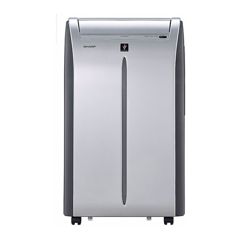
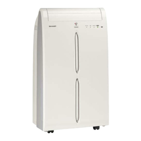
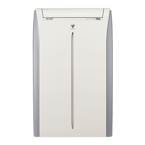
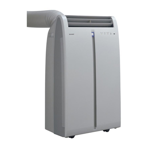
Sharp CV10CTXW User manual

SERVICE MANUAL
CV10CTX
No. S1101CV10CTX
Parts marked with " " are important for maintaining the safety of the set. Be sure to replace these parts with specified ones for maintaining the
safety and performance of the set.
This document has been published to be used for
after sales service only.
The contents are subject to change without notice.
CHAPTER 1. PRODUCT SPECIFICATION
[1] SPECIFICATION ...........................................1-1
[2] ELECTRICAL PARTS.................................... 1-1
[3] WIRING DIAGRAM ....................................... 1-2
[4] EXTERNAL DIMENSION ..............................1-3
[5] PART NAMES ............................................... 1-4
CHAPTER 2. ATTENTION WHEN REPAIRING
[1] HOW TO REPAIR REFRIGERATION ...........2-1
CHAPTER 3. TROUBLESHOOTING GUIDE
[1] TROUBLESHOOTING................................... 3-1
[2] FUNCTION..................................................... 3-4
CHAPTER 4. DISASSEMBLING PROCEDURE
[1] DISASSEMBLING PROCEDURE.................. 4-1
Parts Guide
CONTENTS
PORTABLE AIR CONDITIONER
CV-10CTX-W
CV-10CTX-B
CV-10CTX-S
MODEL
In the interests of user-safety (Required by safety regulations in some countries) the set should
be restored to its original condition and only parts identical to those specified should be used.
High
Low
Auto
Fan only
Dry
Cool
Heat MODE
Min
ON/OFF

1-1
CV10CTX
CHAPTER 1. PRODUCT SPECIFICATION
[1] SPECIFICATION
[2] ELECTRICAL PARTS
MODEL CV-10CTX-W CV-10CTX-B CV-10CTX-S
Cooling Capacity BTU/h 10000 10000 10000
CV-10CTX-W CV-10CTX-B CV-10CTX-S
Running capacitor 450V - 50μF / 250V - 10μF
Fan capacitor (IN/OUT) 250V - 10μF
Thermistor 15kΩ at 77°F (RT1), 20kΩ at 77°F (RT2, RT3)
Fan motor YD45W
Overload relay B350-150-141E/BF1518-JH
Splash motor SN03V
Phase Single
Rated frequency Hz 60
Rated voltage V 115
Rated current A 9 9 9
Rated input W 1250 1250 1250
EER BTU/Wh 8.9 8.9 8.9
Noise level (Hi / Lo) dB (A) 53 / 49 53 / 49 53 / 49
Electrical Data
Type (Hermetically sealed rotary type)
Model, Motor Output YZG-A082Y2D2
(850W)
Compressor
Evaporator Aluminum Fin-copper Tube
Condenser Aluminum Fin-copper Tube
Control O.D. x I.D x Length(mm) Φ2.3 x Φ1.0 x 450
(Capillary Charge)
Refrigerant Volume R-410A (OZ) 16.9
REFRIGERANT SYSTEM
Width Height Depth Inch (mm) 13.4"(340) x 30.7"(780) x 15.5"(394)
Net Weight Lbs 53
NET DIMENSIONS
Width Height Depth Inch (mm) 16.3"(415) x 22.4"(568) x 33.1"(840)
Net Weight Lbs 66
GROSS DIMENSIONS
Indoor side (Evaporator) Centrifugal fan
Outdoor side (Condenser) Centrifugal fan
Air Flow rate (Indoor side) CFM High 176
FAN SYSTEM
Safety devices Compressor:Overload Protector
Internal thermal protector
Air lter Polypropylene net
Power cord length ft 5.3
Power plug type NEMA 5-15P
OTHERS

1-2
CV10CTX
[3] WIRING DIAGRAM
TRANSFORMER
TC
TR-IN TR-OUT
G
ELECTRIC BOX
G
G
SENSOR
N3
C2
RD
FAN
MOTOR
BN
~
M1 YEGN
M2
WATER MOTOR
17
RT1
AP2
DISP1
ROOM TEMP.
DISP2
RD
W7
W6
HIGH-WP
~
BK
WH
COM
NC
SA
BU
W1
COMP.
MOTOR
DISP1
BU WH
BK
YE RD
W4
FAN
RD
W2
DISP2
WATER(WATER1)
N1
AP1
R(M,V)
COMP(4)
L(3)
K201
C1
YE
W3
(1) (2)
C(T,U)
YEGN
COMP
~
S(W,X)
W5
N3
BU
BU(WH)
YEGN(GN) N
BN(BK) L
POWER
ROOM
WATER LEVEL
SWITCH
SAT
TUBE
TUBE TEMP.
RT2
SENSOR

1-3
CV10CTX
[4] EXTERNAL DIMENSION
Unit:inch
High
Min Low
Auto
FAN
SPEED
ON/OFF Fan only
Heat Dry
Cool
MODE
High
Min Low
Auto
FAN
SPEED
ON/OFF Fan only
Heat Dry
Cool
MODE
13.4”
30.7”
15.5”

1-4
CV10CTX
3. Remote control
4. Remote control display
1. MODE Button:Press it to select operation
mode(AUTO/COOL/DRY/FAN)
2. + Button : Press it to increase
temperature setting
3. Not available on this unit
4. TIMER Button: Press it set auto-on/auto-
off timer
5. SLEEP Button
6. FAN Button
7. - Button : Press it to decrease
temperature setting
8. ON/OFF Button : Press it to start or stop
operation
ON/OFF
MODE
FAN
SLEEP TIMER
+
-
AUTO
COOL
DRY
FAN
T-ONT-OFF
SLEEP
LOCK
SPEED
1
2
3
4
5
6
7
8

1-5
CV10CTX
[5] PART NAMES
1
2
3
4
5
6
7
8
9
10
11
12
21
13
14
15
17
16 18 19 20
ON/OFF
MODE
FAN
SLEEP TIMER
+
-
AUTO
COOL
DRY
FAN
T-ONT-OFF
SLEEP
LOCK
SPEED
1. Front view
2. Rear view
1 Control panel and display lamp
2 Remote control signal receiver window
3 Handel
4 Remote controller box
5 Air outlet
6 Vertical louvers
7 Horizontal louvers
8 Wheel
9 Air inlet
10 Grille
11 Air outlet
12 Air inlet
13 Power cord hook
14 Power cord
15 Rear clip (bottom)
16 Rain guard
17 Mothproof net
18 Rear clip (upper)
19 Exhaust hose
20 Joint
21 Remote Controller

2-1
CV10CTX
CHAPTER 2. ATTENTION WHEN REPAIRING
[1] HOW TO REPAIR REFRIGERATION
[1] HOW TO REPAIR REFRIGERATION
Before sealed system work can be preformed a refrigerant recovery EPA and LOCALLY approved certication is required,
additionally, EPA and LOCALLY approved refrigerant recovery equipment is required.
1. Sealed system repair
Sealed system repairs should be properly diagnosed before
entering into a repair of the system.
It is important to follow proper procedures when doing a system
repair for safety reasons and that the repair will result in a
restoration of the system to proper factory standards.
2. Safety reminders
1) Do not heat any system component with an open ame for
any reason.
2) Do not solder until you are sure that all refrigerant has been
removed from the system.
3) Do not heat the charging cylinder with an open ame. Use
warm water only and do not exceed 125 F (not too hot to keep
your hand in.)
4) Do not over ll any charging cylinders, as they could explode
when over lled.
5) Use proper wrenches.
6) Use safety goggles when working with refrigerants.
7) Keep a re extinguisher within easy reach.
8) Watch ame direction when soldering so as not to burn
clothing, wiring or other components.
9) Solder in a well ventilated area. If a high concentration of
freon is present, an open ame will create phosgene gas which
can be harmful.
3. Proper soldering
Joint clearances should be maintained so that the brazing alloy
will ow between the closely mated surfaces rather than forming
large llets.
This lms make the strongest joints, capillary attraction also work
best with close tolerance.
The best clearance is between 0.01" to 0.03", the amount of lap
will be approximately 3/8" depending on the swaging tool used.
4. Cleaning tubing
To make a sound, leak tight joint, the brazing alloy when raised
to brazing temperature, must wet and ow freely over the entire
surface of the tubing in the joint area.
To assure this, the tubing surfaces must be free of all dirt,
grease, oil and oxides otherwise the alloy will not wet and ow
properly over any surface with these elements present. Cleaning
can be done with an abrasive cloth or steel wool. Never blow
into the tubing because this will introduce a lot of moisture into
the system. Open tubing joints should be covered if exposed for
long periods of time.
5. Proper uxing
Flux is necessary when using silver solder; it is not required
when using silfos on copper to copper joints.
To do a good job the ux should cover the tube surface
completely. Be careful not to introduce any ux inside the tubing.
Fluxing should be done after the tubing is mated together and
just before brazing is done. Do not allow it to dry out.
When brazing, the ux should become entirely liquid and clear,
like water. The temperature will be at 1100 F and only a little
more heat will allow the alloy to ow freely into the joint.
GOOD FIT
POOR FIT
Joint Clearance.
PROPER
JOINT FIT
CLEARANCE
0.2mm TO 0.6mm
EMERY CLOTH
KEEP TUBE IN
DOWNWARD POSITION
Cleaning Tubing.
INNER CONE
TORCH STEM
SILVER ALLOY
Directing Torch Flame to Copper Tubing.
10mm

2-2
CV10CTX
6. Heating the tubing
Direct the torch ame so that the larger tube receives most of the heat.
Silver solder ows at 1200 F and silfos ows at 1300 F.
Heat all around the tubing.
The ame is composed of two cones, a smaller inner cone (pale blue)
in calor and a much larger outer cone. The hottest part of the ame is
at the tip of the inner cone. The ame should be directed at the joint
with the tip of the cone just touching the surface of the tubing.
7. Dehydrating sealed system
Many servicers feel that since air conditioners run with evaporator temperatures above 33 F, moisture will not present a problem.
Nothing is further from the truth. Oxygen in moisture plus the heat produced during compression will react with the refrigerant oil to
produce harmful acids in the system which will break down motor winding insulation, create sludge and pit component parts, reducing
efciency of the air conditioner and shortening the life of compressors.
There it becomes mandatory that good dehydrating practices be adhered to at all times.
Proper hook up procedures as shown in Figure 5 must be used in order to pull and good vacuum from the system.
The use of a good vacuum pump is very important so that the boiling point of any water in the system will be lowered to a point where
it will vaporize and be expelled from the system in the form of vapor.
7.1. Type of evacuation methods
1. Piston Type Compressor No good.
System parts must be above 110 F.
2. Rotary Vacuum Pump Disavantages.
Low CFMC. 4 oil gets dirty.
3. Single State Vacuum Pump will not clean oil.
Oil must be changed often.
4. Two Stage Vacuum Pump will reach 50 microns.
First stage is below atmospheric pressure.
Moisture is removed into second stage which works up to atmospheric
pressure thus keeping oil clean.
Manometer cannot be read to 1/2 mm. Micron gauge reads from
25,400 microns to 0.
It becomes clear that good equipment and maintained properly must be used in order to remove air and moisture from the system.
When a vacuum of 1,000 to 500 microns is reached, block off the vacuum pump from the system.
This is done by closing the value between the pump and system. If the micron gauge does not increase above 1,000, the system is
free of moisture and no leak exists. If the micron gauge increases to higher levels moisture or a leak exists.
OUTER CONE
HOTTEST PART
OF FLAME
INNER CONE
TORCH STEM
HIGH VACUUM PUMP
LARGE DIAMETER
BRAIDED VACUUM
HOSES
HIGH VACUUM
MANIFOLD
DIAL-CHARGE
CHARGING CYLINDER
HIGH SIDE
GAUGE
LOW SIDE
GAUGE
ELECTRIC
VACUUM
GAUGE
TO RELATED SERVICE
VALVE OR PROCESS
TUBES OF THE UNIT.
Hook up for Evacuation
and charging

2-3
CV10CTX
8. Leaks
Several methods are used to detect leaks in systems.
● Electronic Leak Detectors are very sensitive and are able to detect leaks down to 1/2 ounce per year.
A good electronic leak detector is generally far better in locating very small leaks.
● Halide Torch be sure the room is free from refrigerant vapours. Watch the ame for the slightest change in calor.
A very faint green indicates a small leak. The ame will be unmistakably changed to green or purple when large leaks are encountered.
To simplify leak detection pressurize the system to approximately 75 lbs.
Some leaks can be located by a visual inspection of the system components and solder joints and if oil is found at any given location it
generally is a sign that a leak exists at that point due to the fact that ame does carry oil with it travels through the system.
● Soap Bubbles
Liquid detergents can sometimes assist in nding small leaks by brushing detergent on the suspect area and watching for bubbles.
Before applying detergent be sure that the system is pressurized.
Tap line devices are permissible for diagnosis only they are not suitable when evacuating the system. After the diagnosis has been
made they must be removed so that the system will be restored to a hermeticly sealed condition.
RUNNING CAPACITOR AND FAN CAPACITOR
NOTE: DISCHARGE THE RUNNING CAPACITOR AND FAN CAPACITOR
BEFORE TOUCHING CAPACITOR OR WIRING.
1) Discharge capacitor by shorting terminals.
2) Take the wires off the capacitor terminals.
3) Set the selector switch of a volt-ohm-meter (or a tester) on the resistance
range.
4) Connect the probes to the capacitor terminals and watch the indicator swing.
The indicator does not swing at all ..... Open.
The indicator swings but does not return ..... Shorted.
The indicator swings, then returns a moment later ..... Good.
1. Insulation test
Check the resistance between the terminals and case.
Reading must be more than 10MΩ at DC 500V.
2. Overload relay
Check continuity between terminals with volt-ohm-meter.
3. Insulation test
Check resistance between terminals and the relay case.
Reading must be more than 10MΩ at DC 500V.
4. Compressor
1) Take the wires off compressor terminals.
2) Set selector switch of volt-ohm-meter on the resistance range.
3) Put the probes on the terminals of the compressor and check continuity
between each terminal.
5. Insulation test
Check the resistance between the terminals and the copper tube.
Reading must be more than 10MΩ at DC 500V.
[2] ELECTRICAL COMPONENT TEST
RUNNING CAPACITOR
FAN CAPACITOR

3-1
CV10CTX
Energize and turn on
the unit
Indoor unit display
F1-F2 ?
Check the connection
status of indoor tem-
perature sensor
Indoor unit displays
F3/F4/F5
whether it's
connected tightly?
Check the connection
status of outdoor
temperature sensor
Whether it's
connected tightly?
Replace temperature
sensor
Is malfunction
eliminated?
Adjust the connection
status
Is malfunction
eliminated?
Is malfunction
eliminated?
Replace main board
of indoor unit
Replace temperature
sensor
Is malfunction
eliminated?
Replace main board
of outdoor unit
Energize and turn on
the unit
yes
yes
yes
yes
no
no
no
no
no
no
no
Adjust the
connection status
1. Failure for Temperature Sensor
Main test point:
● If the outdoor environment temperature is in normal range
● If fan motor normally runs.
● If the radiating environment of indoor and outdoor unit is good
Check the ow process of failure is:
CHAPTER 3. TROUBLESHOOTING GUIDE
[1] TROUBLESHOOTING

3-2
CV10CTX
2. Failure for Switch of Water Level
Y
N
Y
N
N
Y
Y
Y
YY
N
Turn on the unit
Display H8
If the defrosting tray
is over-blow
Refer to the indication
of instruction to discharge
the water of chassis.
Connection line of
water level switch is tight.
Failure is
cancelled.
Adjust
connection
Failure is
cancelled.
Replace the
switch of water
level
Failure is
cancelled.
Replace
control
board
End
Main test point:
● If the defrosting tray is over-blow
● If the connection line of water level switch is good.
● If the water level switch is damaged.
Check the ow process of failure is:

3-3
CV10CTX
3. Overcurrent Protection
Start
Is the supply voltage unstable with big fluctuation?
Is the supply voltage too low with overload?
Is the indoor / outdoor heat exchanger too dirty,
or are the air inlet and outlet blocked?
Measure the current of live wire
on the main board with a clamp ampere meter. Is the
current higher than the value of the overcurrent
protection?
Is the fan motor running abnormally; is the fan speed too
low or does it fail to run?
Is there blockage inside the system?
(Filth blockage, ice plug, greasy blockage, the Y-valve hasn’ t
been opened completely)
Is the compressor running
abnormally? Is there abnormal sound or oil leakage; is
the temperature of the shell too high, etc.?
no
no
no
no
yes
no
no
Replace the control
panel
End
Normal fluctuation is within 10% of the rated voltage on the
nameplate
yes Malfunction is eliminated.
no
Adjust the supply voltage to maintain it within normal range
yes Malfunction is eliminated.
no
Clean the indoor and outdoor heat exchangers and remove
the blockage of air inlet and outlet
yes Malfunction is eliminated.
no
Check the motor and reinstall the motor to have the fan run
normally
yes Malfunction is eliminated.
no
Replace the controller
no Malfunction is eliminated.
no
Flush the heat exchangers with high pressure nitrogen
yes Malfunction is eliminated.
no
Replace the compressor
yes Malfunction is eliminated.
no
yes
yes
yes
yes
yes
yes
yes

3-4
CV10CTX
[2] FUNCTION
The temperature in this manual is expressed by Centigrade.If Fahrenheit is used, the switchover between them is
Tf=TcX1.8+32.
1.Temperature Parameters
◆Indoor preset temperature (Tpreset)
◆Indoor ambient temperature (Tamb.)
2.Basic Functions
Once the compressor is energized, there should be a minimum
interval of 3 minutes between two start-ups. Once the compressor
operates, the unitwill not stop within 6 minutes due to temperature
change.
1)Cool Mode
(a) When Tamb.≥Tpreset+1°C(2°F), the unit starts cooling
operation. In this case, the compressor and motor operate and the
fanoperates at set speed.
(b) When Tamb.≤Tpreset-1°C(2°F), the compressor and the motor
stop while the fan runs at set speed.
(c) When Tpreset-1°C(2°F)<Tamb.<Tpreset+1°C(2°F), the unit
willmaintain its current running status. In cooling mode, temperature
setting range is 16~30°C(61~86°F).
2)Dry Mode
In this mode, the set temperature and ambient temperature will not
be displayed. Fan will operate at low speed while compressor , fan
and motor continuously operate.
3)Fan Mode
In fan mode, set temperature and ambient temperature will not
be displayed. Fan will operate at set speedwhile compressor and
motor stop operating.In this mode, temperature setting range is
16~30°C(61~86°F).
4)AUTO Mode
In AUTO mode, Tpreset in standard cooling is 25°C(77°F) while in
standard heating is 20°C(68°F).
When Tamb.26°C>(79°F), the unit enters auto cooling mode;When
Tamb.20°C<(68°F), the unit enters auto fan mode;
When 20°C(68°F)≤Tamb.≤23°C(73°F) if the unit is in fan mode, it
will keep its status; If not, it will enter auto dry mode;
When 26°C(79°F)≥Tamb.≥24°C(74°F), the unit enters auto dry
mode;
When 26°C(79°F)≥Tamb.≥20°C(74°F), If the unit is energized for
the rst time, it will enter dry mode.
3.Basic Functions
1)Buzzer
Upon energization or availably operating the unit or remote
controller, the buzzer will give out a beep.
2)Sleep Function
(a) After setting the sleep function in cooling mode, Tpreset will
increase1°C(2°F) in 1 hour later and 2°C(4°F) to tally in 2 hours
later.After that, the set temperature will not increase any more and
the upper limit of set temperature after increase is 30°C(86°F).
(b)There is no sleep function in Fan or Dry mode.
(c)After setting sleep function, it will be cancelled by switching
operation mode.
(d)The set temperature displayed on remote controller will not
change with the decrease or increaseof the set temperature in this
mode.
3)Auto Fan
(a)fan speed in cooling mode:
Tamb.≥Tpreset + 2°C(4°F), High speed;
Tpreset<Tamb.<Tpreset +2°C(4°F), Medium speed;
Tamb.≤Tpreset, Low speed;
(b) There is 210s’ delay for switch of Auto Fan mode.
4)Timer function
General Timer
Timer ON can be set at unit OFF. If selected ON time is reached,
the unit will start to operate according to previous setting status.
Time setting range is 0.5-24hr in 30-minute increments.Timer OFF
can be set at unit ON. If selected OFF time is reached, the unit
will stop operation. Time setting range is 0.5-24hr in30-minute
increments.
Clock Timer
Timer ON
If timer ON is set during operation of the unit,the unit will continue
to operate. If timer ON is set at unit OFF, upon ON time reaches the
unit will start to operate according to previous setting status.
Timer OFF
If timer OFF is set at unit OFF, the system will keep stand by status.
If timer OFF is set at unit ON, upon OFF time reaches the unit will
stop operation.
5)Memory Function
If the unit is de-energized, it will operate at the previous mode after
it is energizedagain. If the unit operates before de-energization,the
compressor will operate in 3 min later after the unit is energized
again.
6)Indicator Lamp and “Dual 8” Nixie Tube
(a)When the unit operates at cooling mode, the cooling indicator
lamp is on and “dual 8”nixie tube displays set temperature.
(b)When the unit operates at fan mode, the fan indicator lamp is on
and“dual 8”nixie tube will not display anything.
(c)When the unit operates at dry mode, the dry indicator lamp is on
and “dual 8”nixie tube will not display anything.
7)Button
(a) ON/OFF :control ON/OFF of the unit
(b) Mode: The setting of mode is circulated as the cooling mode、
Dry mode、Fan mode.
(c)/: Press “+” to increase the set temperature while press “-” to
decrease the set temperature when the unit operates.The set
temperature will increase or decrease 1°C or 1°F for each press.
The set temperature can’t be decreased if it reaches 16°C or 61°F
while it can’t be increased when it reaches 30°C or 86°F. In that
case, Auto, Dry or Fan mode will be invalid.
(d) Fan: Fan speed setting circulated as following: low-medium-
high-auto-low.
8)Light Control
If light is turned on by remote control, the indicator lamp and “dual 8”
nixie tube will display the current status. If it is turned off, all lights
will be turned off. If the button on front panel or remote controller
is pressed when the light is turned off, the indicator lamp and “dual
8”nixie tube will display the current status for 5s and then the light
will be turned off. The display of malfunction is not affected by
remote light control.
4.Protection Function
1)Freeze Prevention Protection
When the freeze prevention protection is detected, the compressor
will stop and the fan will operate at set speed. Once such protection
is removed, the previous status will be resumed in 3 minutes later.
2)Overow Prevention Protection
When detecting that the water is full for continuous 3 seconds,
overow prevention protection will occur, malfunction code H8 will
be displayed.

4-1
CV10CTX
CHAPTER 4. DISASSEMBLING PROCEDURE
[1] DISASSEMBLING PROCEDURE
"ACTUAL UNITS MAY VARY SLIGHTLY FROM THOSE PICTURES BELOW"
CAUTION: ● DISCONNECT THE PORTABLE TYPE ROOM AIR CONDITIONER FROM THE POWER SUPPLY BEFORE ANY SERVICE.
● DISCONNECT THE EXHAUST HOSE FROM THE UNIT BEFORE ANY SERVICE.(SEE OPERATION MANUAL)
● DRAINAGE SHOULD BE PERFORMED BEFORE ANY SERVICE.
(SEE "WHENEVER THE UNIT IS MOVED" OF OPERATION MANUAL )
1.Remove the panel sub-assy
panel sub-assy
2.Remove cable collection board
cable collection board
3.Remove grille and filter sub-assy
grille and filter sub-assy
Steps Procedure
Remove the two screws fixing panel sub-assy, lift
to remove the panel sub-assy.
Remove the screws fixing cable collection board,
to remove the board.
Pull outward the grille and filter sub-assy by
hands, to remove them.

4-2
CV10CTX
4.Remove rear board assy
rear board assy
5.Remove front panel sub-assy panel sub-assy
6.Remove display board sub-assy display board sub-assy
7.Remove the electric box sub-assy
electric box cover
electric box sub-assy
cable
Steps Procedure
Remove the six screws fixing rear board, to
remove the rear board assy.
Remove the screws fixing the left, right and back
side of the front panel, to remove the panel
sub-assy.
Remove the fixing screws fixing display board
sub-assy, to remove the display board sub-assy.
Remove the two screws fixing electric box cover,
to remove the electric box cover. Pull off the
connection cable on electric box, remove the
screws fixing electric box, to remove the electric
box sub-assy.

4-3
CV10CTX
8.Remove propeller cover
propeller cover
9.Remove supporting board1
supporting board1
10.Remove connection pipe
welding joint
11.Remove evaporator assy
evaporator
Steps Procedure
Remove the screws fixing propeller cover, to
remove the propeller cover.
Remove the screw fixing supporting board to
remove the board1.
Welding cut the joints on the connection pipe, to
remove the connection pipe. (Discharge the
refrigerant clearly before welding cutting.)
Remove the screws fixing evaporator assy, to
remove the evaporator assy.

4-4
CV10CTX
12.Remove air flue assy
air flue assy
13.Remove upper propeller
upper propeller
14.Remove upper centrifugal fan blade
upper centrifugal
fan blade
15.Remove lower propeller
lower propeller
16.Remove diversion circle
diversion circle
17.Remove lower centrifugal fan blade
lower centrifugal
fan blade
Steps Procedure
Remove the four screws fixing air flue assy, to
remove the air flue assy.
Remove the four screws fixing upper propeller to
remove the upper propeller.
Remove the screw nut and gasket fixing upper
centrifugal fan blade, to remove the upper
centrifugal fan blade.
Remove the three screws fixing lower propeller,
to remove the lower propeller.
Remove the four screws fixing air guide loop, to
remove the diversion circle.
Remove the screw nut and gasket fixing lower
centrifugal fan blade, to remove the lower
centrifugal fan blade.

4-5
CV10CTX
18.Remove motor
water tray
motor
19.Remove water baffle and supporting board 2 3
water
baffle
supporting board
2 3
20.Remove compressor
compressor
21.Remove condenser assy
condenser
assy
22.Remove water splash motor, floatsub-assy and castor
water splash motorsub-assy
float
sub-assy
castor
Steps Procedure
Take off the water tray, remove the three screws
fixing motor, to remove the motor.
Remove the screws fixing water baffle, to remove
the water baffle. Remove the screws fixing
supporting board 2, 3, to remove the supporting
boards.
Remove the three foot screw nuts fixing
compressor, to remove the compressor.
Remove the connecting screw fixing condenser
assy and chassis, to remove the condenser assy.
Remove the screws fixing water splash sub-assy,
to remove the water splash sub-assy.
Remove the screws fixing float sub-assy, to
remove the float sub-assy.
Remove the screws fixing castors, to remove the
castors.

PARTS GUIDE
CONTENTS
Parts marked with " " are important for maintaining the safety of the set. Be sure to replace these
parts with specified ones for maintaining the safety and performance of the set.
This document has been published to be used
for after sales service only.
The contents are subject to change without notice.
CV10CTX
PORTABLE AIR CONDITIONER
CV-10CTX-W
CV-10CTX-B
CV-10CTX-S
MODEL
In the interests of user-safety (Required by safety regulations in some countries) the set should
be restored to its original condition and only parts identical to those specified should be used.
[1] CV-10CTX-W CV-10CTX-B CV-10CTX-S
[2] PACKAGE [3] SUPPLIED ACCESSORIES
High
Low
Auto
Fan only
Dry
Cool
Heat MODE
Min
ON/OFF

2
CV10CTX
[1] CV-10CTX-W CV-10CTX-B CV-10CTX-S
NO. PARTS CODE "PRICE
RANK"
"NEW
MARK"
"PART
RANK" DESCRIPTION
CV-10CTX-W CV-10CTX-B CV-10CTX-S
1 9JQ20006125_K75948 Front Panel Assy [CV-10CTX-W]
1 9JQ20006158_K75948 Front Panel Assy [CV-10CTX-B]
1 9JQ20006161_K75948 Front Panel Assy [CV-10CTX-S]
2 9JQ27226122007 Front Panel 2 [CV-10CTX-W]
2 9JQ27226122008 Front Panel 2 [CV-10CTX-B]
2 9JQ27226122009 Front Panel 2 [CV-10CTX-S]
3 9JQ10516074 Guide Louver 7 [CV-10CTX-W]
3 9JQ1051607402 Guide Louver 7 [CV-10CTX-B]
3 9JQ10516074B Guide Louver 7[CV-10CTX-S]
4 9JQ10516073 Guide Louver 6 [CV-10CTX-W]
4 9JQ1051607302 Guide Louver 6 [CV-10CTX-B]
4 9JQ10516073B Guide Louver 6 [CV-10CTX-S]
5 9JQ10586022 Guide Blade Lever 2 [CV-10CTX-W CV-10CTX-S]
5 9JQ1058602202 Guide Blade Lever 2 [CV-10CTX-B]
6 9JQ2000611602 Front Case [CV-10CTX-W]
6 9JQ27220105240 Front Case [CV-10CTX-B]
6 9JQ2000611602P Front Case [CV-10CTX-S]
7 9JQ30567022 Display Board [CV-10CTX-W CV-10CTX-B CV-10CTX-S]
8 9JQ63066061 Membrane [CV-10CTX-W]
8 9JQ63026168 Membrane [CV-10CTX-B CV-10CTX-S]
9 9JQ03006269 Capillary Sub-assy [CV-10CTX-W CV-10CTX-S]
9 9JQ3006168 Capillary Sub-assy [CV-10CTX-B]
10 9JQ01006098 Evaporator Assy [CV-10CTX-W CV-10CTX-S]
10 9JQ01006090 Evaporator Assy [CV-10CTX-B]
11 9JQ01406272 Electric Box Assy [CV-10CTX-W CV-10CTX-B CV-10CTX-S]
12 9JQ7671101601 Partition Pole (PC board) [CV-10CTX-W CV-10CTX-B CV-10CTX-S]
13 9JQ33000046 Capacitor CBB65 [CV-10CTX-W CV-10CTX-B CV-10CTX-S]
14 9JQ01406050 Electric Box Sub-Assy [CV-10CTX-W CV-10CTX-B CV-10CTX-S]
36
56
72 73
46
22
11
1
4
59
48
61
2
6
3
5
10
9
8
7
12
13
14
15
16
17 18 19 20 23
21 24 25 26 27 28 29 30 31 32 33 34 35
37
38
39
40
41
42
43
44
45
47
49
50
51
52
53
54 55
57 58 60
67
68
69
70
71
63
62
64
65
66
74
75
76
77
This manual suits for next models
2
Table of contents
Other Sharp Air Conditioner manuals

Sharp
Sharp Plasmacluster GS-XP07FR User manual

Sharp
Sharp AF-S60RX User manual

Sharp
Sharp CV-P10PR User manual

Sharp
Sharp AF-S60RX User manual

Sharp
Sharp AE-X4M30PU User manual

Sharp
Sharp CV-P10RC User manual

Sharp
Sharp AU-1802Y User manual

Sharp
Sharp AY-XPM7FR User manual

Sharp
Sharp AY-XM09BE User manual

Sharp
Sharp AH-XP10UXD User manual

Sharp
Sharp AY-X36RU User manual

Sharp
Sharp AF-S85NX User manual

Sharp
Sharp AY-X12PSR User manual

Sharp
Sharp CV-P09LX User manual

Sharp
Sharp AY-M09AE User manual

Sharp
Sharp AF-T908X User manual

Sharp
Sharp AF-A9LA User manual

Sharp
Sharp AH-AP9SMD User manual

Sharp
Sharp CV-P10LJ User manual

Sharp
Sharp AH-XPC9RV User manual