manuals.online logo
Brands
  1. Home
  2. •
  3. Brands
  4. •
  5. Sharp
  6. •
  7. Air Conditioner
  8. •
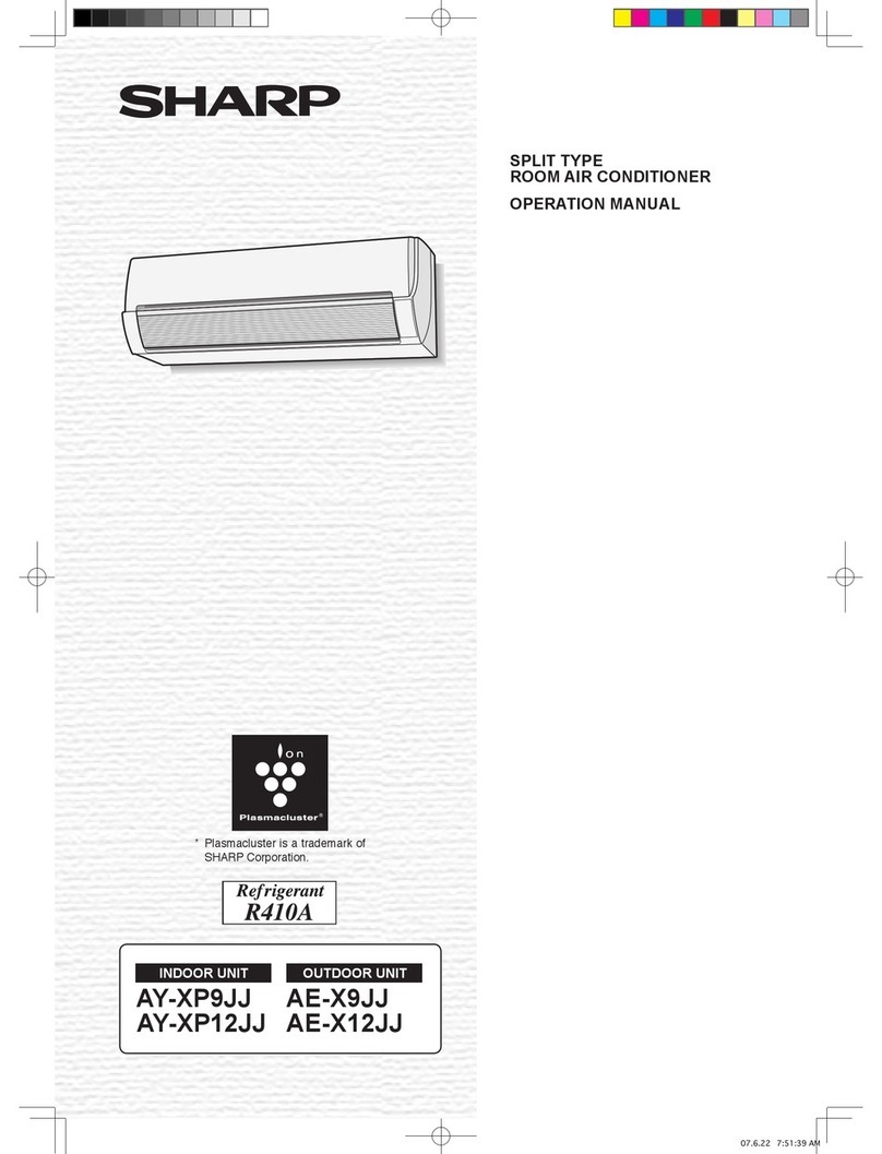
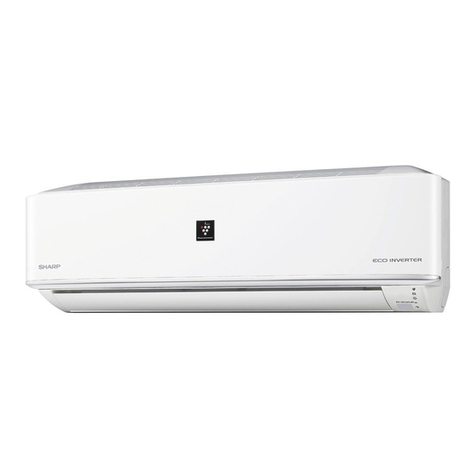
  9. Sharp AH-XPC9RV User manual

Sharp AH-XPC9RV User manual

860
108
A
125
J
175
115
I
F
E
D
J
E
A
F
I
D
292
45
30
Mounting the indoor unit
For right side piping
(1) Pass the pipes and the drain hose through the
piping hole.
(2) Hook the unit onto the mounting plate.
(3) Pull the connecting cable into the indoor unit.
(4) Push the unit and apply the bottom hooks to the
mounting plate's support.
(5) Pull the bottom of the unit to check that the unit
For left side piping
(1) Reverse the positions of the drain hose and
drain cap. Refer to “Exchange the drain hose”.
(2) Connect the pipes and wrap tape around the in-
sulation of the piping joints tightly not to become
thick.
(3) Bind the pipes and connecting cable with tape.
(4) Set the pipes and connecting cable along the
back of the unit, and attach the piping holder.
(5) Pass the pipes, connecting cable and the drain
hose through the piping hole.
(6) Hook the unit onto the mounting plate.
(7) Push the unit and apply the bottom hooks to the
mounting plate's support.
(8) Pull the bottom of the unit to check that the unit
Notes:
•Bend the pipes carefully as not to damage them.
•Lay the drain hose below the pipes.
(1) Remove the screw and pull out the drain
hose.
(2) Pull out the drain cap.
(3) Reconnect the drain hose to the right
and insert the drain cap to the left.
•Fully insert the drain hose until it stops and
•Insert a hexagon wrench (4 mm diagonal)
into the drain cap, and press it fully.
Caution:
After replacing, make sure that both the drain
ITEMS
Q’ty
APPLICATION ITEMS
Q’ty
APPLICATION ITEMS
Q’ty
APPLICATION
1MOUNTING PLATE
1
To mount the indoor
unit on the wall.
4DRY BATTERY
2
For the remote con-
trol.
AAA batteries.
6
REMOTE CONTROL
HOLDER
1
To mount the remote
control on the wall.
2LONG SCREW
(M4.5x30)
7
plate with the wall
plugs.
5SHORT SCREW
(M4x20)
2
REMOTE
CONTROL HOLD-
ER.
7CABLE COVER
1
To secure the cable.
3REMOTE CON-
TROL
1
To control remotely.
1
COVER
8
MANUALS
1
Installation manual
1
Operation manual
INSTALLATION DIAGRAM
Drain Hose
MOUNTING PLATE
Taping
NOTES ON LOCATIONS
Provide as much installation space as possible for
Drain Cap
ACCESSORIES
SAFETY PRECAUTIONS
•Installation must be made in accordance with the installation
manual by service personnel.
•Be sure to use the attached accessories parts and parts
for installation.
falling.
•The appliance shall be installed in accordance with national wir-
ing regulations.
•After installation has complete, check that there is no leakage of
refrigerant gas.
•Ventilate the room if refrigerant gas leaks during installation.
•Use the electrical cable.
Make sure the cable is secured in place and that the terminals are free
result.
•Form the cable so that the control box cover, the cord holder and
cable holder are not loose.
OPER
INSTALL
Drain Hose
Hexagon wrench
Drain cap
Drain Hose
Screw
Drain Cap
1.
entire room.
2.
Make a drain hose hole for easy drainage.
3. both sides and above the unit.
4.
5.
Keep TV set, radio and the like 1 m or more away from the
unit and the remote
control.
6. Keep the air inlet clear of obstacles that could block incoming air.
7.
The remote control may not function properly in a room equipped
with an electronic
lighting.
8.
Select a location that does not cause loud operation noise
and extreme vibrations.
2
SETTING UP THE INDOOR UNIT
Piping route
zone
without leaving any sharp edge.
(Keep the cut-out plate for possible future use.)
Plate Cut the plate along
notch.
Plate
Plate
Hook
MOUNTING PLATE
SPLIT TYPE ROOM AIR CONDITIONER
INSTALLATION MANUAL B510
AH-XPC9RV
AH-XPC12RV
ENGLISH
•Tighten the nut with a torque wrench according to the
method.
long time and cause refrigerant gas leakage.
•When installing the unit, take care not to enter air substance other
than the refrigerant(R410A) in the refrigerant cycle.
Otherwise, it will cause burst and injury as a result of abnormal high pres-
sure in the refrigerant cycle.
•Be sure to connect the refrigerant pipe before running the compres-
sor.
Otherwise, it will cause burst and injury as a result of abnormal high pres-
sure in the refrigerant cycle.
•Earth the unit.
Incomplete earth may cause electrical shock.
•Install an earth leakage breaker to avoid electric shock in case of
leak.
Use the current-activated, high-sensitivity, high-speed type breaker with a
rated sensitivity current of below 30 mA and an operating time of below 0.1
second.
•Arrange the drain hose to ensure smooth drainage.
• This room air conditioner uses refrigerant R410A.
Use the .
Carefully read and follow these instructions for
smooth and trouble-free installation.
Screw
Tape
Insulation
Piping holder
Use the refrigerant pipes shown in the table below.
Pipe size Pipe
thickness Thermal insulation
Liquid
side
1/4"
(ø 6.35 mm) 0.8 mm
Thickness:
6 mm or thicker
Material:
Polyethylene foam
Gas
side
3/8"
(ø 9.52 mm)
•The thermal insulation should cover both the gas and liquid
pipes.
Exchange the drain hose
1
23
4
5
This manual describes the installation of indoor unit only
For the installation of the outdoor unit, see the installation manual accompanying outdoor unit.
Wall
1
PLACING THE MOUNTING PLATE AND MAKING A PIPING HOLE
Installing the mounting plate
(1) Referring to the “INSTALLATION
DIMENSION OF INDOOR UNIT”,
holes and the piping hole.
marked in circle around the hole.
(7 points)
• Make sure that the mounting
plate is horizontally.
(2) Secure the mounting plate to the
wall with the long screws and
check the stiffness.
1MOUNTING PLATE 2LONG SCREW
Indoor Outdoor
Cut with a saw.
Cap
5 mm
Sleeve (Downward to
outdoor
)
Length unit: mm
Center of wall hole
Center of wall hole
Outline of indoor unit
(unit size)
(unit size)
INSTALLATION DIMENSION OF INDOOR UNIT
Making a piping hole
(1) Drill a piping hole
with 70mm diameter
concrete drill or a hole
saw with a 5mm down
ward slant to the out-
side.
(2) Set the sleeve and
caps.
Tape
Pipes
Drain Hose
50 mm or more
50 mm or more
50 mm or more
70 mm or more
Coating tape
(Commercially
available)
A3AHXPC9_2RV_B510.indd 1 2011-8-11 8:13:41
(3)
(2)
(4)
(1)
Not running wavy.
Not left in water.
5
CONNECTING THE REFRIGERANT PIPES
No trap
allowed. Not to rise.
Connecting the drain hose
(1) Connect a drain hose.
(2) Tape over the connecting part.
Drain hose
ø16 mm
Connecting the pipes
outdoor unit.
(1)
(2) Use a wrench and torque wrench to tighten up the pipes.
•Do not over tighten the pipes. It may be deformed or
damaged.
Flare nut tightening torque
Pipe size Torque
Liquid side 1/4"
(ø 6.35 mm) 16 ± 2 N·m (1.6 ± 0.2 kgf·m)
Gas side 3/8"
(ø 9.52 mm) 38 ± 4 N·m (3.8 ± 0.4 kgf·m)
4
CONNECTING THE DRAIN HOSE
No trap allowed.
90°
A
Notes:
•
•
Be careful not to allow the drain hose to rise, form a trap or
leave its end in
water, as shown below.
•Coil thermal insulation around a drain hose extension, if run-
ning in the room.
7
TEST RUN
(1) Start the operation with the remote control.
(2) To start test run in cooling, hold down the AUX button on the unit
for over 5 seconds until a beep sound is heard and an operation
(3) Make sure the system runs well.
To stop the operation, press the AUX button again.
8 ITEMS TO CHECK
Is the earth wire connected properly arranged?
Is the drainage properly?
Is there any gas leakage at the pipe connection?
EXPLANATION TO CUSTOMER
• Explain to the customer how to use and maintain the system, referring to the operation manual.
•Ask the customer to carefully read the operation manual.
• When the system has been set up, hand the installation manual to the customer.
TINS-B510JBRZ
“ “ mark
Fix the remote control holder
to the wall with the short
screws.
6 REMOTE CONTROL
HOLDER
5 SHORT SCREW
Loading the batteries
(1) Slide and open the cover.
(2) Insert the batteries.
(3) Replace the cover.
(4) Press the RESET button using a thin
stick.
6
HANGING THE REMOTE CONTROL
DETACHING THE FRONT PANEL
For servicing, for example, detach the front panel in the fol-
lowing steps. Be sure to disconnect the power cable from
the wall outlet or turn off the circuit breaker.
(1)
(2) Unscrew the 2 screws of the front panel.
(3)
(4) Remove the front panel.
•Slightly open the lower part of the front panel, and extract
the 5 hooks along the upper surface for disassembly.
(5) Screw
DETACHING THE UNIT FROM THE MOUNTING PLATE
Push the “ “ marks at the bottom of the indoor unit and pull the bottom of
the unit. When the hooks are released from the mounting plate, support the
bottom of the unit and lift the unit upwards.
Checking drainage
(1) Open the open panel.
(2)
(3) Pour some water into the
drain pan.
(4) Check the water drains
smoothly.
Use a copper cable.(Cross-section area 1.0 mm2)
-
ible cord (code designation 60245 IEC 57).
(1) Process the end of the connecting cable for the indoor side.
(2) Open the open panel.
(3) Connect the cable.
(4) Fix the cable with the cable cover and the short screw.
(5) Close the open panel.
Cautions:
•Be sure to put the cable leads deep into the terminal board and
malfunction.
•Be very careful not to confuse the terminal connections. Wrong
cabling may damage the internal control circuit.
•Be sure to connect the cable to match the markings on the indoor
unit’s terminal board and those of the outdoor unit.
8 mm
8 mm
40 mm
50 mm
3
CONNECTING THE CABLE TO THE INDOOR UNIT
Earth wire
Flare nut
Wrench
Torque wrench
(4) Flaring
Flare processing
dimensions(A)
(5) Checking
Flare nut not missing.
Flaring the pipe end
(1) Cutting with a pipe cutter
Cut at a right angle.
(2) Deburring
Allow no cuttings in the pipe.
Tool A
R410A tool 0 - 0.5 mm
Conventional tool 1.0 - 1.5 mm
N1 2
5 SHORT SCREW
7 CABLE COVER
Connecting cable
Earth wire
Terminal board
AUX
(3) Wind coating tape around refrigerant pipes to-
gether with drain hose and cable for general.
•Lay the drain hose below the pipes.
•The thermal insulation
should cover both the gas
and liquid pipe. As insulation,
use polyethylene foam 6 mm
or thicker.
Liquid pipe
Gas pipe Insulation
Drain hose
Cable
A3AHXPC9_2RV_B510.indd 2 2011-8-11 8:13:43

Other manuals for AH-XPC9RV

1

This manual suits for next models

1

Other Sharp Air Conditioner manuals

Sharp AE-A189J User manual

Sharp

Sharp AE-A189J User manual

Sharp AH-S327W2 User manual

Sharp

Sharp AH-S327W2 User manual

Sharp AY-XP08CE User manual

Sharp

Sharp AY-XP08CE User manual

Sharp AY-XPC9RR User manual

Sharp

Sharp AY-XPC9RR User manual

Sharp AY-XP07ER User manual

Sharp

Sharp AY-XP07ER User manual

Sharp AF-R80CX User manual

Sharp

Sharp AF-R80CX User manual

Sharp AE-XM30GR User manual

Sharp

Sharp AE-XM30GR User manual

Sharp CV10CTXW User manual

Sharp

Sharp CV10CTXW User manual

Sharp AE-X26FR-N User manual

Sharp

Sharp AE-X26FR-N User manual

Sharp AH-S22DP2 User manual

Sharp

Sharp AH-S22DP2 User manual

Sharp AY-AP12FHR User manual

Sharp

Sharp AY-AP12FHR User manual

Sharp CV-2P10SX User manual

Sharp

Sharp CV-2P10SX User manual

Sharp AY-AP7FHR User manual

Sharp

Sharp AY-AP7FHR User manual

Sharp AF-05CML User manual

Sharp

Sharp AF-05CML User manual

Sharp AH-X075E User manual

Sharp

Sharp AH-X075E User manual

Sharp AH-AP09CF User manual

Sharp

Sharp AH-AP09CF User manual

Sharp AY-XPC12PU User manual

Sharp

Sharp AY-XPC12PU User manual

Sharp AH-A07CR User manual

Sharp

Sharp AH-A07CR User manual

Sharp AF-S85NX User manual

Sharp

Sharp AF-S85NX User manual

Sharp AH-XP10UXD User manual

Sharp

Sharp AH-XP10UXD User manual

Sharp AH-X08BE User manual

Sharp

Sharp AH-X08BE User manual

Sharp AH-N45DP2 User manual

Sharp

Sharp AH-N45DP2 User manual

Sharp AH-A9FEF User manual

Sharp

Sharp AH-A9FEF User manual

Sharp Plasmacluster GS-XP07ER User manual

Sharp

Sharp Plasmacluster GS-XP07ER User manual

Popular Air Conditioner manuals by other brands

Mitsubishi Electric CITY MULTI PUMY-P NHMU installation manual

Mitsubishi Electric

Mitsubishi Electric CITY MULTI PUMY-P NHMU installation manual

DURASTAR DRAL12F1A installation manual

DURASTAR

DURASTAR DRAL12F1A installation manual

REMKO MVX Series Operating and installation instructions

REMKO

REMKO MVX Series Operating and installation instructions

Daikin FXSQ05TAVJU engineering data

Daikin

Daikin FXSQ05TAVJU engineering data

DAEWOO ELECTRONICS DWC-084R Service manual

DAEWOO ELECTRONICS

DAEWOO ELECTRONICS DWC-084R Service manual

York PREDATOR 102 Technical guide

York

York PREDATOR 102 Technical guide

KINZO BL-168DLR instruction manual

KINZO

KINZO BL-168DLR instruction manual

Electra WNG 50 DCI Service manual

Electra

Electra WNG 50 DCI Service manual

Bryant DURAPAC 579F User's information manual

Bryant

Bryant DURAPAC 579F User's information manual

Soleus Air PAC12 user manual

Soleus Air

Soleus Air PAC12 user manual

Whirlpool ACD052MM0 Use and care guide

Whirlpool

Whirlpool ACD052MM0 Use and care guide

Perfect Comfort PCAA Series Installation, operation and maintenance manual

Perfect Comfort

Perfect Comfort PCAA Series Installation, operation and maintenance manual

Trane 4DCL4024 Installer's guide

Trane

Trane 4DCL4024 Installer's guide

Friedrich MD24Y3J Svc manual

Friedrich

Friedrich MD24Y3J Svc manual

Kaysun KCI-35 DR12 owner's manual

Kaysun

Kaysun KCI-35 DR12 owner's manual

Daikin Super Multi NX FTXS60GV1B installation manual

Daikin

Daikin Super Multi NX FTXS60GV1B installation manual

Carrier 48TC series installation instructions

Carrier

Carrier 48TC series installation instructions

Arctic King WWK15CR71N user manual

Arctic King

Arctic King WWK15CR71N user manual

manuals.online logo
manuals.online logoBrands
  • About & Mission
  • Contact us
  • Privacy Policy
  • Terms and Conditions

Copyright 2025 Manuals.Online. All Rights Reserved.