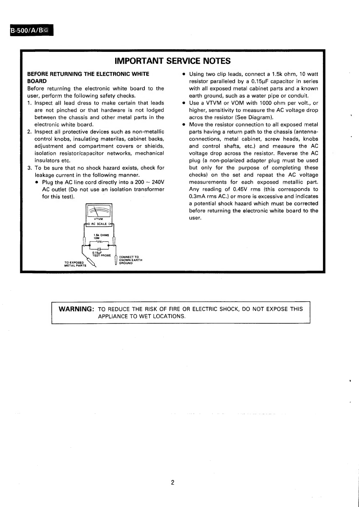
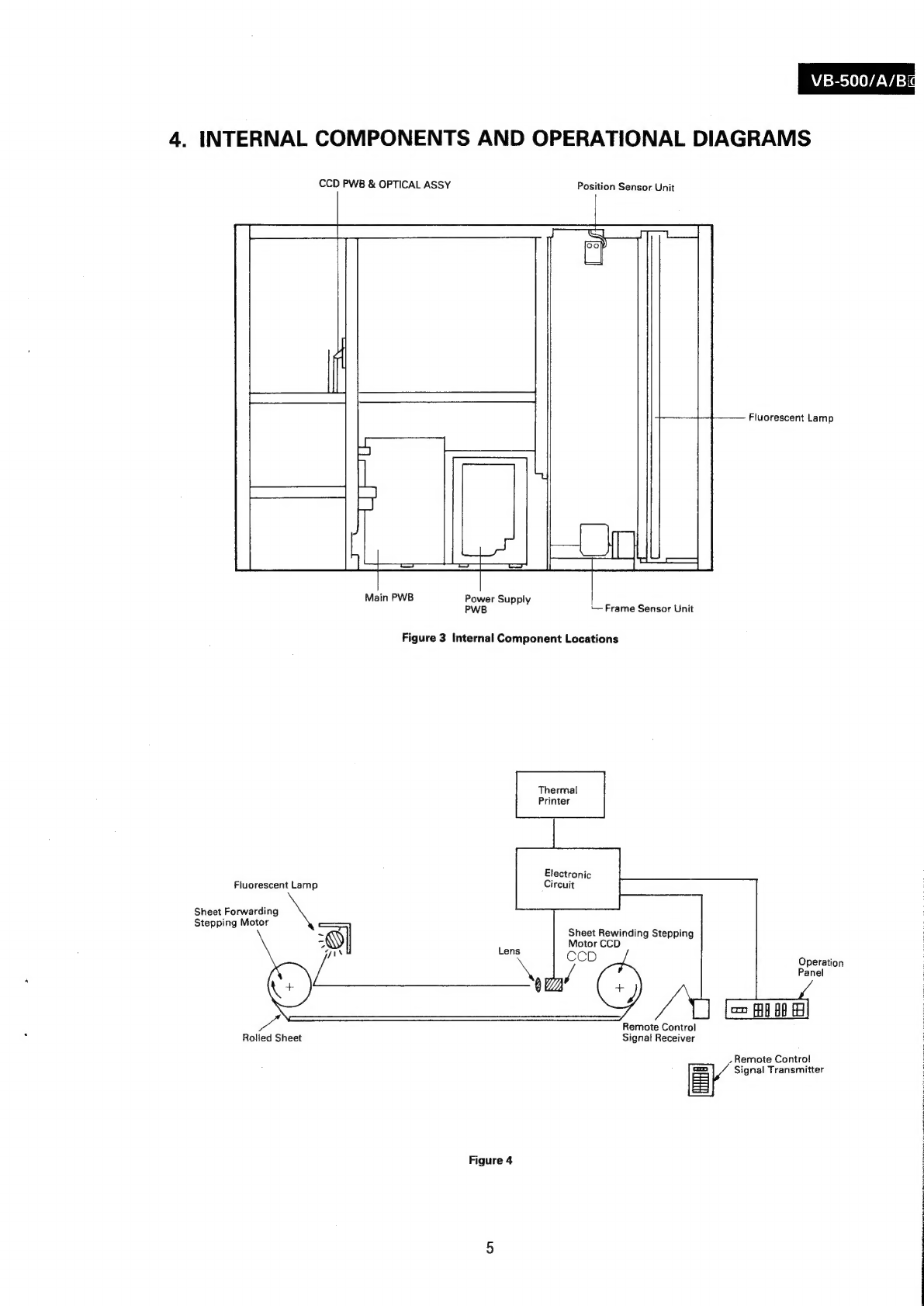
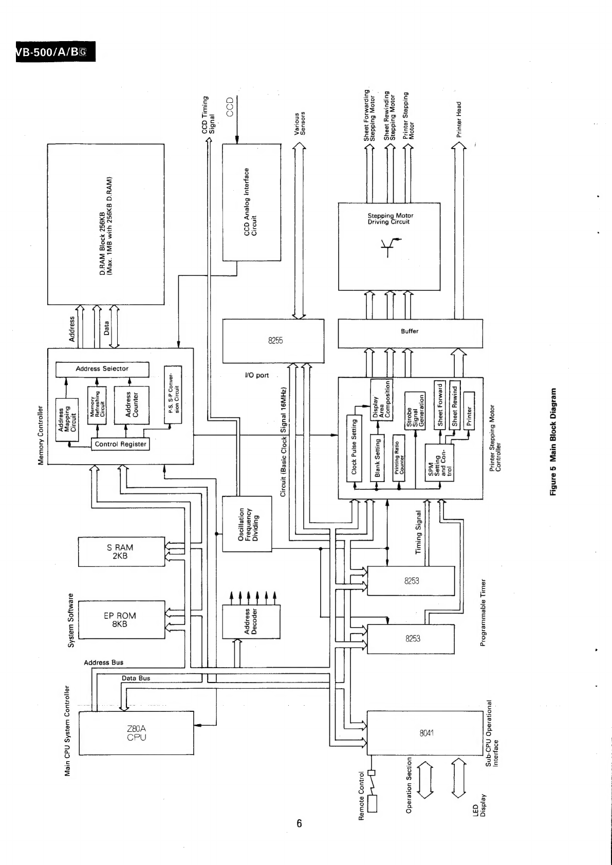
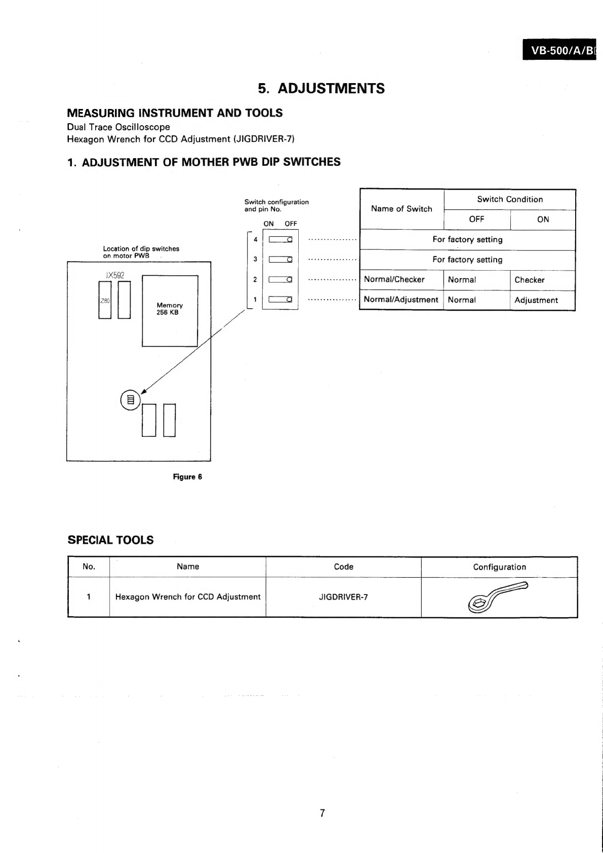
Sharp VB-500/A/BG User manual

VB-500/A/BG
SHARP
SERVICE
MANUAL
SERVICE-HANDBUCH
\
red
SY5K5VB500G//
ELECTRONIC
WHITE
BOARD
ELEKTRONISCHE
SCHAUTAFEL
MODEL/MODELL
VB-500/A/B
iG
In
the
interests
of
user-safety
(Required
by
safety
regulations
in
some
countries)
the
set
should
be
restored
to
its
original
condition
and
only
parts
identical
to
those
specified
should
be
used.
tm
Interesse
der
Benutzer-Sicherheit
(verlangt
von
den
Sicherheitsvor-
schriften
einiger
Lander)
sollte
das
Gerat
wieder
auf
seinen
urspringli-
chen
Zustand
eingestellt
und
nur
die
vorgeschriebenen
Teile
verwen-
det
werden.
SECTION/TEIL
I
CONTENTS
ON
OARPWN>
1.
2.
3.
4.
5.
6.
7.
8.
SHARP
CORPORATION

B-500/A/BiG
IMPORTANT
SERVICE
NOTES
BEFORE
RETURNING
THE
ELECTRONIC
WHITE
e
BOARD
Before
returning
the
electronic
white
board
to
the
user,
perform
the
following
safety
checks.
1.
Inspect
all
lead
dress
to
make
certain
that
leads
are
not
pinched
or
that
hardware
is
not
lodged
between
the
chassis
and
other
metal
parts
in
the
electronic
white
board.
.
Inspect
all
protective
devices
such
as
non-metallic
control
knobs,
insulating
materilas,
cabinet
backs,
adjustment
and
compartment
covers
or
shields,
isolation
resistor/capacitor
networks,
mechanical
insulators
etc.
.
To
be
sure
that
no
shock
hazard
exists,
check
for
leakage
current
in
the
following
manner.
@
Plug
the
AC
line
cord
directly
into
a
200
~
240V
AC
outlet
(Do
not
use
an
isolation
transformer
for
this
test).
VTVM
©
AC
SCALE
O
O.15uF
TEST
PROBE
()
connect
TO
KNOWN
EARTH
TO
EXPOSEO
\
GROUND
METAL
PARTS
Using
two
clip
leads,
connect
a
1.5k
ohm,
10
watt
resistor
paralleled
by
a
0.15yF
capacitor
in
series
with
all
exposed
metal
cabinet
parts
and
a
known
earth
ground,
such
as
a
water
pipe
or
conduit.
Use
a
VTVM
or
VOM
with
1000
ohm
per
volt.,
or
higher,
sensitivity
to
measure
the
AC
voltage
drop
acros
the
resistor
(See
Diagram).
Move
the
resistor
connection
to
all
exposed
metal
parts
having
a
return
path
to
the
chassis
(antenna-
connections,
metal
cabinet,
screw
heads,
knobs
and
control
shafts,
etc.)
and
measure
the
AC
voltage
drop
across
the
resistor.
Reverse
the
AC
plug
(a
non-polarized
adapter
plug
must
be
used
but
only
for
the
purpose
of
completing
these
checks)
on
the
set
and
repeat
the
AC
voltage
measurements
for
each
exposed
metallic
part.
Any
reading
of
0.45V
rms
(this
corresponds
to
0.3mA
rms
AC.)
or
more
is
excessive
and
indicates
a
potential
shock
hazard
which
must
be
corrected
before
returning
the
electronic
white
board
to
the
user.
WARNING:
TO
REDUCE
THE
RISK
OF
FIRE
OR
ELECTRIC
SHOCK,
DO
NOT
EXPOSE
THIS
APPLIANCE
TO
WET
LOCATIONS.

VB-500/A/B
1.
FEATURES
1)
Remote
controlled
operation
2)
May
be
stopped
at
any
point
using
<J>
and
stop
keys.
3)
In
addition
to
1-frame
copy,
compressed
copying
is
AVAILABLE
for
A
2
frame
consecutive
copy
and
A
4
frame
copy.
4)
Direct
selection
of
A
desired
FRAME
1
to
5.
(FRAME
5
cannot
be
copied.)
5}
Additional
printing
can
be
made
even
after
comple-
tion
of
printing.
(Last
Copy
IN
MEMORY.)
2.
SPECIFICATIONS
WHITE
BOARD
Board
Surface
Size
92.0
x
128.0
cm
(36-742
x
50-%
inches)
Effective
Width
of
Board
Surface
88.0
x
124.0
cm
(34-242
x
48-1%6
inches)
Number
of
Frames
5
Frames
Number
of
Copyable
Frames
4
Frames
RECORDER
Recording
Paper
Heat
sensitive
recording
paper
Copy
Size
A4
size
(210
x
297
mm)
Copy
Speed
20
sec/sheet
(ist
copy)
10
sec/sheet
(From
2nd
copy)
5.9
dots/mm
1
~
99
(Number
of
copies
can
be
increased
by
pushing
the
addi-
tional
printing
key.)
Copy
Color
Black
Recording
Density
Number
of
Copies
Picture
Memory
One
white
sheet
(256
KB)
Outside
Dimensions
149.0
(W)
x
66.3
(D)
x
196.5
(H)
(58-232
xX
26-Ve
X
77-1V32
inches)
Weight
Approx.
65
kg
(143
LBS.)
Power
Source
AC200-—240V
(50/60
Hz}
Power
Consumption
Approx.
180
W
during
operation
BTU:
Approx.
90
W
during
stand-by
ACCESSORIES
Heat
sensitive
recording
Paper
..........cccesseeeseeeenenes
1
Markers
(Black,
Blue,
Red)
..........ccscccccccseessnseeeereees
1
Each
EASOR
eecsvcsuvstccaciecienisitevizsicesedtvasedivaiecgers
oussuatiauevedne
1
MQ
MG
t
sisi
ccccssetdicsecepaseciearcasseencand
covsscuvsaizeccesseviariasees
1
Remote
control
transmitter
..........ccccccssseeessreeeeeeenees
1
Battery:
sissivisvs
sostaseesssacsvsvess
indeessivedanvesscecswiasadecstess
cee
2
Instruction
Manual
o........
ce
eeeesssseesseeceereesesseseeeeseenes
1
Manual
for
Unpackaging
and
Assembly
...........
1
*Specifications
subject
to
change
without
notice

B-500/A/BIS
3.
EXTERNAL
COMPONENT
IDENTIFICATION
FRONT
White
Sheet
REAR
Recording
Paper
-
Cover
Printer
Cover
Tray
Ass’y
Part
‘A’
Tray
Ass’y
Part
‘B’
Magnet
Fixing
Area
?
Caster
Figure
1
RS
|
BSS
Printer
Cross
Bar
‘A’
AC
Power
Cable
Figure
2
4
Remote
Control
Signal
Receiver
Display
Remote
Control
Unit
Holder

VB-500/A/Bid
4.
INTERNAL
COMPONENTS
AND
OPERATIONAL
DIAGRAMS
CCD
PWB
&
OPTICAL
ASSY
Position
Sensor
Unit
Fluorescent
Lamp
Main
PWB
Power
Supply
;
PWB
—
Frame
Sensor
Unit
Figure
3
Internal
Component
Locations
Thermal
Printer
Electronic
Fluorescent
Lamp
Circuit
Sheet
Forwarding
tepping
Motor
eiPepne
~
Sheet
Rewinding
Stepping
WY
L
Motor
CCD
Ain
ae
-
Rolled
Sheet
Signat
Receiver
Operation
Panel
Remote
Control
Remote
Control
Signal
Transmitter
Figure
4

weaGeig
yo0/q
uleEW
g
aunBiy
49|}013003
4oVOW
Buddays
sayug
ade
p9}u|
yeuonesadg
MdQ-qns
Jaw)
ajqewuuelboig
ie
-*
4]
Aejdsiq
qa
peta
ONE
ete
8041
==
-,
uonvag
uoneladG
8253
JO,OYy
Hidieie
ini
sow
Buiddars
¢¢
J
Bulpuimay
3884S
TayunoD
oney
Bunuig
uoljsoduwo7s
ealy
Aejdsig
Stepping
Motor
Driving
Circuit
JOjuOD
ajOWeYy
{—
aqons
—
4ojo-:
Buiddais
Suipienios
issue
5
;
3
a
S10SUaS
SNoueA
ite)
w
ic)
Wnasy
aoepaju)
Bojyeuy
G90
Goo
(ZHWL
leuBis
]42019
S1seg)
yNoIID
Burptaiq
Japooag
AQuanbai4
sseuppy
UO!e)|I9SQ
VO
port
leuBis
Buiwi,
goo
wna
uors
-IBAUOD
d-S
“S-d
na
5
a
sD
Jayunod
a
pa
S
‘
>
=
=
NO
5
ssauppy
2
7
o
S
o
?
&
i
3
rN
oO
a
{(WVY'O
8992
44M
EWI
xe)
Oo
=
(e)
AT
o
aygsz
19018
We'd
*
URHD
6
g
Ree
el
8
Burysesjay
3
Ms
5D
<
as
2
Ssaippy
Und)
alemyos
warshs
Buiddew
4a{josju0y
WayshS
dD
WIeW
sseuppy
49@}}04jU09
Aiowayy

5.
ADJUSTMENTS
MEASURING
INSTRUMENT
AND
TOOLS
Dual
Trace
Oscilloscope
Hexagon
Wrench
for
CCD
Adjustment
(JIGDRIVER-7)
1.
ADJUSTMENT
OF
MOTHER
PWB
DIP
SWITCHES
Switch
configuration
and
pin
No.
ON
OFF
4;
C9
Location
of
dip
switches
on
motor
PWB~.
3!
cc
Figure
6
SPECIAL
TOOLS
Name
Name
of
Switch
VB-500/A/Bi
Switch
Condition
OFF
ON
For
factory
setting
For
factory
setting
Normal/Checker
Normal
Checker
Code
Normal/Adjustment
Normal
Adjustment
Configuration
Hexagon
Wrench
for
CCD
Adjustment
JIGDRIVER-7

B-500/A/B&
ADJUSTMENT
PATTERNS
Set
to
the
bottom
of
the
sheet
and
stick
there.
(A)
(B)
Width
9mm
(Shallow
mark)
Draw
3~5
horizon-
tal
lines
with
a
red
marker
at
the
top,
center
and
bottom
of
the
sheet.
Adjust
to
the
sheet.
(C)
a
crossing
on
the
sheet
Draw
approx.
5cm
vertical
lines
with
a
marker
at
8mm
from
each
crossing,
at
the
top,
center
and
bottom,
in
the
left
side.
Figure
7
Draw
horizontal
line
with
a
mar-
ker
at
25mm
from
the
bottom
of
the
first
sheet.

VB-500/A/B
2.
FUNCTION
OF
CCD
PWB
COMPONENTS
AND
TEST
POINT
LOCATIONS
Main
PWB
GND
TP4
CCDOUTPUT
TP3
PR
Reference
pulse
for
read-out
range
(TP1)
[]
J
ue
Lens
holder
LPR
NB
RA
Figure
8
Angle
adjustment
plate
CCD
PWB
Adjustment
of
read-out
position
(angle
adjustment)
Adjustment
of
read-out
range
in
vertical
direction.
Keep
the
screw
Loose
and
turn
the
hexagon
nut.
Turn
the
hexagon
nut
while
keeping
the
rotational
adjustment
screw
Loose.
Figure
9
Angle
Adjustment
Plate
Light
Volume
Adjustment
Plate
Angle
Adjustment
ang
Screw
1
t
Lens
Fixing
Screw
Lens
1
od
NX
)
Lens
Focus
Adjustment
CCD
PWB
Lens
Holder
Franie
Figure
10

B-500/A/BG
3.
CCD
Adjustment
Adjustment
Pattern
Adjustment
Procedures
@
Preliminary
Adjustment
Turn
on
dip
switch
1
and
the
power
switch.
Check
the
output
waveforms
of
TP1
and
TP3
with
an
oscilloscope.
Oscilloscope
Range
0.5msec
2V/div
®
Make
a
preliminary
adjustment
of
the
lens
focus,
so
that
the
CCD
output
can
be
obtained
which
corresponds
nearly
to
the
reference
pulse
width
within
the
read-out
range.
Set
the
gain
control
at
Min
position.
Keep
the
light
volume
adjustment
plate
in
the
open
state.
Fix
each
screw
lightly.
Short-circuit
R223
and
R226
of
CCD
PWB.
Keep
the
optic
axis
at
lower
than
the
saturation
point
(to
ensure
no
variation).
@
Adjustment
of
Lens
(Focus
Dis-
tance)
short-circuit
R223
and
R226
Make
the
adjustment
so
that
the
checkers
of
the
white
sheet
or
the
marking
will
become
deepest
against
the
level
of
white.
Fix
the
lens
by
tightening
the
screws.
Oscilloscope
Range
0.5msec
2V/div
®
Adjustment
of
Read-Out
Range
Short-circuit
R223
and
R226.
Adjust
the
left
edge
of
the
TP1
pulse
to
the
marking
25
mm
dis-
tant
from
the
bottom
end
of
the
white
sheet
by
turning
the
hex-
agon
nut
@
of
Figure
9.
Then
fix
the
nuts
@
and
@.
TP1
Reference
pulse
-out
{
of
sheet
]
1
1
TP3
1
«
Signal
25
mm
mark
Make
adjustment
by
turning
the
hexagon
nut
of
CCD
PWB,
and
fi
j
Haadcubeanga
ix
after
adjustment.
Osilloscope
Range
0.2msec
2V/div
@
Adjustment
of
Optic
Axis
(Angle
Adjustment)
Short-circuit
R223
and
R226.
Turn
the
screw
©
of
Figure
9
until
the
mark
in
the
center
of
pattern
©
comes
down
to
the
lowest
posi-
tion.
When
viewed
from
the
lens
side,
the
read-out
position
is
8
mm
closer
to
the
board
from
the
area
brightened
by
reflection
of
fluores-
cent
lamp.
SS
Reference
pulse
Area
with
reflection
of
fluorescent
lamp
Make
adjustment
by
turning
the
angle
adjustment
screw
so
that
the
mark
in
the
middle
comes
to
the
center
of
waveform
(read-out
reference
pulse).
8mm
Adjustment
position
Osilloscope
Range
0.5msec
2V/div
10

CCD
Adjustment
Adjustment
Pattern
Adjustment
Procedures
VB-500/A/B&
©
Adjustment
of
Rotational
Direction
Short-circuit
R223
and
R226.
Make
the
adjustment
by
turning
the
hexagon
nut
®)
of
Figure
9
so
that
the
marks
in
pattern
©
all
appear.
Fix
the
nuts
©)
and
©
after
adjust-
ment.
©
[_____]
Angle
adjustment
Turn
to
adjust
Tighten
the
screws.
(5
~
6
kg.
cm)
Lens
holder
Oscilloscope
Range
0.5msec
2V/div
©
Adjustment
of
Waveform
Keep
open
R223
and
R226.
eAfter
turning
on
the
power
switch,
Let
the
unit
Warm
up
for
at
Least
10
minutes.
eClose
the
rear
cover
at
fluores-
cent
lamp
side.
Move
the
light
volume
adjustment
plate
so
that
the
output
waveform
of
TP3
becomes
flat
within
the
reference
pulse
range
(at
TP1).
Fix
the
light
volume
adjustment
plate
after
adjustment.
,
Reference
pulse
for
|
read-out
range
|
i
Make
adjustment
so
that
the
waveform
becomes
flat
within
the
reference
pulse
range.
Fix
the
light
volume
adjustment
plate
after
adjustment.
Oscilloscope
Range
0.5msec
2V/div
i
ae
Light
volume
adjustment
plate
@
Gain
Adjustment
Keep
open
R223
and
R226
Make
the
adjustment
at
the
rear
cover
of
fluorescent
lamp
side
and
in
a
darkroom.
eAfter
turning
on
the
power
switch,
Let
the
unit
warm
up
for
at
Least
10
minutes
prior
to
adjustment.
Adjust
R220
on
the
CCD
PWB
to
obtain
the
output
of
6V+05V.
Oscilloscope
Range
0.5msec
1V/div
Screw
Locking
Apply
screw-lock
to
the
screws.
Apply
screw-lock
to
the
screw,
hexagon
nut
and
lens
holder.
Apply
screw-lock
to
the
screw.
Apply
screw-lock
to
the
lens
fixing
Apply
screw-lock
to
Screw
the
screw,hexagon
nut
and
PWB.
Apply
screw-lock
to
the
screws.
Apply
screw-lock
to
the
screw.
11

B-500/A/BIG
4.
SIMPLIFIED
ADJUSTMENT
PROCEDURES
FOR
CCD
PWB
WITHOUT
USING
AN
OSCILLOSCOPE
Caution
The
procedures
described
below,
simplified
adjustment
methods
may
be
used
when
the
electronic
white
board
is,
for
instance,
moved
from
one
place
to
another
and
requires
readjustment.
When
conducting
this
adjust-
ment,
be
sure
not
to
move
the
lens
and
the
light
volume
adjustment
plate,
readjustment
of
the
Lens
require
the
use
of
an
oscilloscope.
Never
touch
the
red
marked
screws,
since
an
oscillo-
scope
is
also
required
for
their
adjustment.
1.
Adjustment
of
the
Read-Out
Range
Preparation
(1)
Remove
the
rear
cover
and
install
the
printer.
(2)
Remove
the
front
frame
and
turn
on
the
power
switch.
After
the
initial
setting,
select
the
4th
Frame.
(3)
Draw
horizontal
lines
with
the
marker
at
two
posi-
tions,
35
mm
from
the
upper
and
the
lower
ends
of
the
writing
white
sheet
as
shown
in
Figure
7.
(4)
Loosen
the
screws
@
and
@’
shown
in
Figure
9.
—
\
Main
body
Stretch
the
chart
of
Figure
13
like
this
way.
Read-out
position
Roll
white
sheet
Aluminum
sash
Board
position
of
first
Page
white
sheet
Figure
11
Brightened
area
due
to
reflection
of
fluorescent
lamp.
Adjust
the
reference
line
of
Figure
13
chart
to
this
position.
Adjustment
point
of
Figure
13
chart.
12
Adjustment
(1)
Make
a
copy
of
the
4th
Frame
and
check
that
the
horizontal
lines
on
the
writing
sheet
are
copied.
(2)
When
the
lines
are
not
copied,
turn
the
hexagon
nut
below
the
screw
@)
using
the
adjustment
Tool
while
making
a
copy
of
the
4th
Frame.
This
hexagon
nut
has
endless
turn
construction,
which
brings
the
nut
Back
to
its
initial
position
when
it
is
turned
360°.
In
making
the
adjustment,
therefore,
turn
this
nut
in
one
direction
until
the
point
is
found
where
both
of
the
horizontal
lines
are
copied.
(3)
Tighten
the
screws
@
and
@’.
Make
copy
of
the
4th
Frame
again
and
check
that
the
upper
and
the
lower
horizontal
lines
are
printed.
Then
apply
screw-lock
to
those
screws
to
finish
the
adjustment.
2.
Adjustment
of
the
Read-Out
Position
Preparation
(1)
Remove
the
rear
cover
and
install
the
printer.
(2)
Attach
the
adjustment
chart
in
such
way
that
the
marks
A-A
shown
in
Figure
13
will
come
precisely
to
the
edges
of
the
frame
as
shown
in
Figure
13-1.
(3)
Attach
the
“BOARD”
of
the
chart
at
the
other
side
of
A-A
marks
to
the
inside
of
the
aluminum
sash
while
avoiding
slackness.
(4)
Turn
on
the
power
switch
and
make
initial
setting.
Aluminum
sash
White
sh
eet
Figuret
3
chart
Figure
12

VB-500/A/B
Aluminum
Sash
Figure
13-1
Upper
Side
Adjustment
Point
OsL
Reference
Line
chart
and
stick
it
to
the
Adjust
this
mark
to
the
edge
ae
of
the
frame.
Stretch
the
aluminum
sash
of
the
board.
Lower
Side
To
be
pasted.
Not
to
paste
this
area.
To
be
pasted
Figure
13
Chart
for
Positional
Adjustment
13

B-500/A/BG
Adjustment
(1)
(2)
(4)
Make
a
copy
of
one
frame
and
check
its
printing
condition.
When
the
resultant
print
is
like
the
one
shown
in
Figure
14,
turn
the
screw
©
shown
in
Figure
9
slowly
counterclockwise
while
making
copy
of
one
frame.
Stop
the
screw
when
the
print
becomes
like
the
one
shown
in
Figure
15.
At
this
point,
the
adjustment
is
finished.
When
the
print
is
like
the
one
shown
in
Figure
16,
turn
the
screw
(©)
clockwise
to
adjust
to
the
condi-
tion
shown
in
Figure
15.
Apply
screw-lock
to
the
screw
©
to
finish
the
adjustment.
3.
Adjustment
of
Print
Distortion
Preparation
(1)
(2)
(3)
(4)
Remove
the
rear
cover
and
install
the
printer.
Turn
on
the
power
switch
and
make
initial
setting.
Draw
a
perpendicular
line
with
a
black
marker
along
with
an
arbitray
vertical
line
at
the
centre
of
the
writing
white
sheet.
Loosen
the
screws
©
and
(
shown
in
Figure
9.
Adjustment
(1)
(2)
(3)
(4)
(5)
(6)
(7)
Make
a
copy
of
the
frame
with
the
vertical
line.
Check
the
condition
of
the
copied
line.
When
the
vertical
line
is
printed
like
the
way
as
shown
in
Figure
17,
turn
the
hexagon
nut
®
in
Figure
9
counterclockwise
using
the
adjustment
Tool
until
the
line
becomes
like
the
one
shown
in
Figure
18.
When
the
line
is
printed
like
Figure
20,
turn
the
hexagon
nut
clockwise
until
the
line
be-
comes
like
Figure
18
or
19.
(In
some
cases,
the
vertical
line
like
Figure
19
is
printed
as
a
result
of
the
read-out
timing.
This
poses
no
problem
for
the
adjustment.)
Make
copy
of
the
vertical
line
several
times
and
repeat
this
adjustment
until
the
slope
of
the
printed
-
vertical
line
becomes
linear.
After
completion
of
adjustment,
fix
the
screws
©
and
(by.
Then
make
a
copy
of
the
vertical
line
again
and
check
that
the
adjustment
is
completely
done.
Check
the
reading-out
and
if
anything
wrong
is
found,
make
readjustment
according
to
the
proce-
dure
of
“2
Adjustment
of
Read-Out
Position”
on
page
13.
Apply
screw-lock
to
the
screws
(©)
and
(®’
to
finish
the
adjustment.
14
Figure
14
pe
Ns
2]
Se
aero
Figure
16
Vertical
li
Figure
17
Turn
the
screw
©
counterclockwise.
Eee
Ee
Gee
Figure
15
Turn
the
screw
©
clockwise.
ne
©
Hexagon
nut
@)
Figure
18
Depending
on
the
timing
of
read-out,
the
vertical
fine
may
be
printed
as
shown
in
the
left.
This
causes
no
problem
for
adjustment.
Figure
19
Oo=
Hexagon
nut
@)
Figure
20

VB-500/A/Bi
6.
REPLACEMENT
OF
WRITING
SHEET
1)
Disassembly
*Turn
off
the
power
switch
and
lock
the
casters
before
Performing
the
Replacement.
(1)
Remove
the
two
screws
at
the
right
and
left
sides
of
the
front
frame.
Pull
out
the
right
or
left
bottom
corner
of
the
front
frame
and
detach
the
bottom
of
the
front
frame.
Hold
the
top
and
the
bottom
of
the
frame
and
lift
it
up
at
an
angle
to
Detach
the
hooks
and
Remove
to
dismount
the
front
frame
from
the
main
body
frame.
(Figure
21)
(2
—
Figure
23
(6)
Detach
the
sheet
from
the
writing
sheet
holder.
(Figure
24)
(2)
Remove
the
nine
screws
at
the
bottom
of
the
board.
(Figure
22)
Figure
24
(7)
Plug
in
the
power
supply
cord
and
turn
on
the
power
switch.
(8)
Confirm,
by
the
E6
status
indicator,
that
the
white
sheet
is
stationary.
Push
the
Frame
Shift
button
|
>
and
left
the
white
sheet
completely
Wind
up
on
the
right
side.
(A
noise
will
be
heard
if
the
button
is
kept
pushed
after
the
white
sheet_is
all
wound
up.
Push
the
Frame
Shift
button
[STOP]
to
stop
the
white
sheet
before
the
noise
is
produced.)
Turn
off
the
power
switch.
Note:
If
the
noise
is
not
stopped,
the
white
sheet
may
be
dislocated
from
the
white
sheet
rail.
When
the
noise
is
heard,
push
the
[STOP]
button
or
turn
off
the
power
switch
promptly.
Figure
22.
(3)
Remove
the
nine
screws
at
the
top
of
the
board.
(4)
Pull
out
the
bottom
of
a
board
unit.
(Figure
23)
Besure
that
Lower
Supports
Lock
into
Position.
(5)
Hold
the
top
and
the
bottom
of
the
board
at
the
board
centre.
While
lifting
the
board
a
little,
pull
out
the
top,
keeping
the
main
body
and
the
frame
in
parallel.
15
Sim
NS
A
I
re
tt
Be
Pi
ed
SA
ne

B-500/A/BIG
(9)
Push
the
brake
solenoid
under
the
right
side
of
the
sheet
board
to
release
the
brake.
Pull
out
the
white
sheet
by
hand
slowly.
(Figure
25)
\
\
Figure
26
(10)
Push
the
sheet
bobbin
holder
lever
in
the
upper
part
of
the
right
side
Board,
and
remove
the
upper
part
of
the
white
sheet
bobbin.
(Figure
26)
/'I
f:
(11)
Lift
up
the
white
sheet
bobbin
and
draw
it
out
from
the
lower
white
sheet
holder.
(12)
While
rolling
up
the
white
sheet
TIGHTLY
on
the
bobbin
which
was
drawn
out,
carry
the
bobbin
from
the
right
side
of
the
board
to
the
left
side.
(Figure
27)
Figure
27
(13)
On
the
left
side,
follow
the
same
procedures
as
described
in
(10)
and
(11)
to
draw
out
the
bobbin.
(14)
After
taking
out the
bobbin,
retain
it
with
a
rubber
band.
(Figure
28)
Figure
28
2)
Reassembly
(1)
Wind
up
the
white
sheet
TIGHTLY
on
the
right
side
roll.
(2)
For
replacement
of
the
white
sheet,
take
out
the
roll
hub
unit
from
the
removed
white
sheet,
and
insert
it
to
the
new
white
sheet
bobbin.
Figure
29

(3)
(4)
(5)
(6)
(7)
(8)
(9)
(10)
(11)
(12)
While
Holding
the
white
sheet,
insert
the
bobbin
into
the
bobbin
holder
in
the
bottom
left
of
the
board,
match
the
notch
of
the
bobbin,
to
the
Notch
DF
Press
the
upper
part
of
the
white
sheet
bobbin
into
the
notch
of
the
upper
white
sheet
holder
to
complete
the
installation
of
the
left
side
white
sheet
bobbin.
While
paying
attention
not
to
loosen
the
Rolled
up
end
of
the
white
sheet,
feed
out
the
white
sheet
slowly
and
carry
it
to
the
right
side
of
the
board.
Note:
When
moving
to
the
right
side,
press
the
upper
and
the
lower
ends
of
the
bobbin
lightly
with
your
fingers
to
contact
them
to
the
board
face
for
parallel
movement.
Insert
the
white
sheet
bobbin
into
the
bobbin
holder,
matching
the
lower
side
notch
of
the
sheet
bobbin
to
the
bobbin
holder.
Press
the
upper
part
of
the
white
sheet
bobbin
into
the
notch
of
the
upper
white
sheet
holder
to
complete
the
installation
of
the
right
side
white
sheet
bobbin.
Piug
in
the
power
supply
cord
and
turn
on
the
power
switch
for
an
E6
indication.
Push
the
Frame
Shift
button[<]
to
wind
up
the
white sheet
towards
the
Left
for
about
5
seconds.
Then
turn
off
the
power
switch.
Insert
the
white
sheet
between
the
white
sheet
holder
and
the
board
at
both
upper
and
lower
ends.
Turn
on
the
power
switch
again
and
check
that
the
initial
setting
is
correctly
made.
Note:
(The
unit
is
in
normal
condition
if
the
indica-
tor
displays
FRAME
1
and
COPIES
0.)
Hold
the
top
and
the
bottom
of
the
board
at
the
board
center,
and
while
lifting
the
board
a
little,
hook
it
on
the
main
frame
with
the
upper
part
fixture.
Press
upon
the
stay
at
the
bottom
inside
of
the
board
lightly
with
your
hand
and
Reform
it.
Press
the
bottom
of
the
board
against
the
main
frame.
Figure
30
17
VB-500/A/Bi
Lever
=
¢
3
Figure
31
|
PUSH
Figure
32
(13)
Fix
the
top
and
the
bottom
of
the
board
to
the
main
frame
with
the
18
screws
respectively.
(14).
Hook
the-fixture
to-the
upper.part
of
the
front
frame
on
the
main
frame.
At
this
time,
check
that
the
board
is
hooked
securely.
(15)
Match
the
roller
catch
angle
holder
at
the
bottom
of
the
front
frame
to
the
roller
catch
B.

B-500/A/BE
7.
REPLACEMENT
OF
ROTATIONAL
MECHANISM
UNIT
Caution:
The
rotational
mechanism
unit
has
been
adjusted
be-
fore
shipment
to
provide
its
best
operational
accuracy,
and
when
its
replacement
is
needed,
due
care
must
be
taken
not
to
impair
its
accuracy
by
observing
the
procedures
shown
below.
Disassembly
of
Rotational
Mechanism
Unit
(1)
(2)
(3)
Unscrew
the
paper
tray,
paper
guide,
printer
and
rear
cover
in
this
order,
and
remove
the
rear
cover.
Remove
the
writing
sheet
according
to
the
instruc-
tion
in
“Replacement
of
Writing
Sheet”
and
store
it.
e@
Disconnect
the
connectors
PA
and
RO
at
the
photointerrupter
PWB,
and
remove
the
leads
from
the
lead
holder.
Return
the
writing
sheet
board
to
its
specified
position,
and
temporarily
fix
two
screws
at
the
centre
of
the
board,
one
each
at
the
upper
and
(4)
(5)
(6)
lower
parts.
Disconnect
the
relay
connector
which
is
used
to
connect
the
plunger
leads
coming
from
the
rota-
tional
mechanism
units
(right
and
left)
to
the
main
PWB,
and
then
the
connectors
RE
and
FF
which
are
used
to
connect
the
motor
leads
to
the
main
PWB.
And
remove
the
leads
from
the
lead
holders
and
leave
them
near
the
right
and/or
rotational
mechan-
ism
unit.
Remove
eight
screws,
two
each
at
the
places
@),
©,
©
and
@,
shown
in
Fig.
33.
Remove
the
screws
which
have
temporarily
fixed
the
writing
sheet
board,
and
detach
the
writing
sheet
board
from
the
main
body.
At
the
time,
be
careful
not
to
allow
the
leads
of
the
rotational
mechanism
unit
to
be
entwined
between
the
main
body
and
writing
sheet
board.
Connector
PA
Connector
RO
Figure
33
Rotational
Mechanism
Unit
with
Rear
Cover
Removed
Figure
34
Rear
View
of
Rotational
Mechanism
Unit
(at
Right
Side)
18

(7)
Remove
the
screws
@,
@,
©, @,
©
and
©
shown
in
Fig.
34
from
the
rotational
mechanism
unit
(at
right
side),
and
detach
the
rotational
mechanism
unit
from
the
writing
sheet
board.
The
same
proce-
dures
apply
to
removal
of
the
left
rotational
mechanism
unit.
Reassembly
of
Rotational
Mechanism
Unit
(1)
Referring
to
the
assembly
drawing
of
the
rotational
mechanism
unit
shown
in
Fig.
34,
align
the
screw
holes
of
the
rotational
mechanism
unit
with
those
of
the
writing
sheet
board.
Then
temporarily
fix
the
screw
();
this
screw
is
used
as
a
datum
screw
to
decide
the
accuracy
of
the
rotational
mechanism
unit.
(2)
Also
referring
to
Fig.
34,
temporarily
fix
the
screw
@
which
is
used
to
decide
the
accuracy
in
the
vertical
direction
and
secure
the
screw
@)
complete-
ly.
Then
secure
the
screw
@)
firmly
and
fix
the
screws
@),
@,
©
and
©
in
this
order.
(3)
The
same
procedures
apply
to
reassembly
of
the
left
rotational
mechanism
unit.
(4)
Attach
the
writing
sheet
board,
with
the
rotational
mechanism
unit
secured
on
it,
to
the
main
body
and
19
(5)
(6)*
(7)
(8)
VB-500/A/Bi
temporarily
fix
the
two
screws
at
the
center
of
the
board,
one
each
at
the
upper
and
lower
parts.
(At
the
time,
be
careful
not
to
allow
the
leads
of
the
rotational
mechanism
unit
to
be
entwined
between
the
rotational
mechanism
board
and
main
body.)
Referring
to
Fig.
33
secure
the
screws
at
the
places
@, ©,
©
and
@.
@
Connect
the
connectors
PA
and
RO
at
the
photo-
interrupter
PWB
and
arrange
the
leads
using
the
lead
holder.
Connect
the
plunger
lead
(coming
from
the
rota-
tional
mechanism
unit)
to
the
relay
connector
and
the
leads
(coming
from
the
motor)
to
the
connec-
tors
RE
and
FF
at
the
main
PWB.
Arrange
the
leads
using
the
lead
holders.
Remove
the
two
screws
which
have
temporarily
fixed
the
writing
sheet
board
and
attach
the
writing
sheet
to
the
board
according
to
the
instruction
in
“Attachment
of
Writing
Sheet”.
Attach
the
rear
cover,
printer,
paper
guide
and
paper
tray
in
this
order
to
the
main
body.
Thus,
replacement
of
the
rotational
mechanism
unit
is
completed.
a
TERS
E
ee
er
ee
LEP
PT
Ae
een
Le

B-500/A/BIG
8.
ARRANGEMENT
OF
COMPONENTS
10}01/
PUN
JaMOg
Se
aanBiy
yun
Jayjow
y89ys
||0"
due}
juaosaiony4
yun
sosuas
abeg
yun
Josuas
uoNIsog
JOU.
sue]
aje)d
juawysnipe
AWNIOA
14617
wun
goo
J@9Ys
|10Y
y
ywunan
4aaiaze.
jeuBis
[04}U09
aoWaY
20
Table of contents
Languages:
Other Sharp Interactive Whiteboard manuals