Sharp R-3H57 User manual

R-3H57
SHARP CORPORATION
SERVICE MANUAL
In interests of user-safety the oven should be restored to its original
condition and only parts identical to those specified should be used.
MODEL R-3H57
S8502R3H57PJZ
MICROWAVE OVEN
TABLE OF CONTENTS Page
CAUTION, MICROWAVE RADIATION ................................................................................................................ 1
WARNING..............................................................................................................................................................1
PRODUCT SPECIFICATIONS............................................................................................................................. 2
GENERAL INFORMATION ................................................................................................................................... 2
APPEARANCE VIEW........................................................................................................................................... 3
OPERATION SEQUENCE ................................................................................................................................... 4
FUNCTION OF IMPORTANT COMPONENTS .................................................................................................... 5
SERVICING .......................................................................................................................................................... 7
TEST PROCEDURE ............................................................................................................................................ 9
TOUCH CONTROL PANEL ................................................................................................................................ 18
COMPONENT REPLACEMENT AND ADJUSTMENT PROCEDURE............................................................... 24
MICROWAVE MEASUREMENT ........................................................................................................................ 30
WIRING DIAGRAM ............................................................................................................................................. 31
PICTORIAL DIAGRAM....................................................................................................................................... 33
CONTROL PANEL CIRCUIT .............................................................................................................................. 35
PRINTED WIRING BOARD ................................................................................................................................ 36
PARTS LIST........................................................................................................................................................ 37

R-3H57

R-3H57
1
SERVICE MANUAL
PRODUCT SPECIFICATIONS
SHARP CORPORATION
OSAKA, JAPAN
TEST PROCEDURE
SERVICING AND
TROUBLESHOOTING CHART
FUNCTION OF IMPORTANT
COMPONENTS
OPERATING SEQUENCE
APPEARANCE VIEW
MICROWAVE MEASUREMENT
WIRING DIAGRAM
PARTS LIST
TOUCH CONTROL PANEL
ASSEMBLY
COMPONENT REPLACEMENT
AND ADJUSTMENT PROCEDURE
MICROWAVE OVEN
R-3H57
GENERAL IMPORTANT INFORMATION
ThisManualhasbeenpreparedtoprovideSharpCorp.Service
engineers with Operation and Service Information.
It is recommended that service engineers carefully study the
entire text of this manual, so they will be qualified to render
satisfactory customer service.
CAUTION
MICROWAVE RADIATION
DO NOT BECOME EXPOSED TO RADIATION FROM
THE MICROWAVE GENERATOR OR OTHER PARTS
CONDUCTING MICROWAVE ENERGY.
Serviceengineersshouldnotbeexposedtothemicrowave
energy which may radiate from the magnetron or other
microwave generating devices if it is improperly used or
connected. All input and output microwave connections,
waveguides, flanges and gaskets must be secured. Never
operate the device without a microwave energy absorbing
load attached. Never look into an open waveguide or
antenna while the device is energized.
WARNING
Never operate the oven until the following points are ensured.
(A) The door is tightly closed.
(B) The door brackets and hinges are not defective.
(C) The door packing is not damaged.
(D) The door is not deformed or warped.
(E) There is not any other visible damage with the oven.
Servicing and repair work must be carried out only by trained
service engineers.
All the parts marked "*" on parts list are used at voltages more
than 250V.
Removal of the outer wrap gives access to potentials above
250V.
All the parts marked "∆" on parts list may cause undue
microwave exposure, by themselves, or when they are dam-
aged, loosened or removed.

R-3H57
2
PRODUCT SPECIFICATIONS
ITEM DESCRIPTION
Power Requirements 240 Volts (for Australia) / 230 - 240 Volts (for New Zealand)
50 Hertz
Single phase, 3 wire earthed
Power Consumption 1.37kW
Power Output 900 watts nominal of RF microwave energy (IEC 705)
750 watts (2 litre water load)
Operating fequency 2450 MHz
Case Dimensions Width 520 mm
Height 305 mm including foot
Depth 389 mm
Cooking Cavity Dimensions Width 348 mm
Height 197 mm
Depth 368 mm
Turntable diameter 325mm
Control Complement Touch Control System
Clock ( 1:00 - 12:59)
Timer (0 - 99 minutes 99 seconds)
Microwave Power for Variable Cooking
Repetition Rate;
HIGH............................................... Full power throughout the cooking time
MEDIUM HIGH .................................................. approx. 70% of Full Power
MEDIUM .............................................................approx. 50% of Full Power
MEDIUM LOW ....................................................approx. 30% of Full Power
LOW ................................................................... approx. 10% of Full Power
HELP pad
SENSOR COOK pads
SENSOR INSTANT ACTION pads
NUMBER pads
POWER LEVEL pad
EASY DEFROST pad
MEMORY pads
MORE, LESS pads
CLOCK pad
TIMER pad
STOP/CLEAR pad
AUTO START pad
INSTANT COOK/START pad
Set Weight Approx. 15 kg
GENERAL INFORMATION
WARNING
THIS APPLIANCE MUST BE EARTHED
IMPOTANT
THE WIRES IN THIS MAINS LEAD ARE COLOURED IN ACCORDANCE WITH THE FOLLOWING CODE:
GREEN-AND-YELLOW : EARTH
BLUE : NEUTRAL
BROWN : LIVE

R-3H57
3
8
9
10
4 2
713
5
3
6
11
14
4
1
12
APPEARANCE VIEW
1. Ventilation openings
2. Oven lamp
3. Door hinges
4. Door safety latches
5. See through door
6. Door seals and sealing
surfaces
7. Coupling
8. Door open button
9. Touch control panel
10.Digital readout
11.Waveguide cover
12.Power supply cord
13.Rating label
14.Menu label
Indicator
COOK KGSENSOR DEF HELP
HELP
SENSOR COOK
MEAT
Fresh Vegetables
Jacket Potato
Reheat Beverage
Fish Fillets
STOP
CLEAR AUTO
START
DESSERTS
RICE
PASTA
VEGETABLES
Info Display
INSTANT COOK
START
POWER
LEVEL EASY
DEFROST
TIMER
LESS MORE
CLOCK
MEMORY
1MEMORY
2
1 2 3 4 5
6 7 8 9 O
SMART
&EASY
REHEAT
SENSOR COOK PADS
Press to select Sensor Cook
mode.
NUMBER PADS
Press to enter cooking times, clock
time, weight or quantity of food.
POWER LEVEL PAD
Press to select microwave power
setting. If not pressed, HIGH is
automatically selected.
EASY DEFROST PAD
Press to defrost meat by entering
weight.
MORE ( ), LESS ( ) PADS
Press to increase/decrease the
time in one minute increments
during cooking or to alter the
doneness for the Convenience
Meals or Information Cook modes.
STOP/CLEAR PAD
Press to clear during programming.
Press once to stop operation of
oven during cooking; press twice
to cancel cooking programme.
HELP PAD
Press to select information guide
on/off, child lock or demonstration
modes.
Press to get cooking information.
SENSOR INSTANT ACTION PADS
Press once to cook 1 of 4 popular
menus.
MEMORY PADS
Press to enter two frequently used
cooking programmes.
Press to recall the memorized
programme.
TIMER PAD
Press to set Timer.
CLOCK PAD
Press to set Clock
INSTANT COOK/START PAD
Press once to cook for 1 minute at
HIGH or increase by 1 minute multiples
each time this pad is pressed during
cooking.
Press to start oven after setting
programmes.
AUTO START PAD
Press to set Auto Start time.
TOUCH CONTROL PANEL

R-3H57
4
OPERATION SEQUENCE
OFF CONDITION
Closing the door activates all door interlock switches
(1st. latch switch, 2nd. latch switch and stop switch).
IMPORTANT
When the oven door is closed, the monitor switch contacts
(COM-NC) must be open.
When the microwave oven is plugged in a wall outlet, rated
voltage is supplied to the point A3+A5 in the control unit.
Figure O-1 on page 31
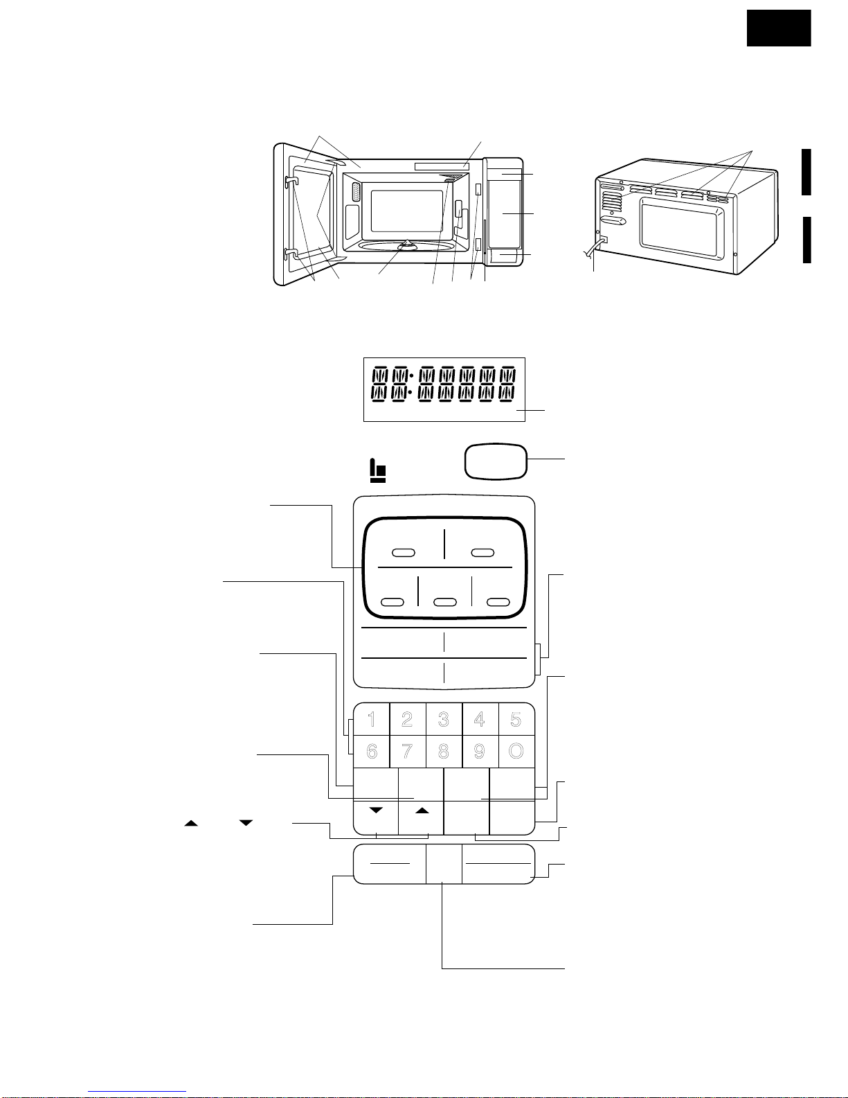
1. The display shows SHARP , MICRO- , WAVE
and OVEN .
2. To set any programmes or set the clock, you must first
touch the STOP/CLEAR pad.
3. : appears in the display.
NOTE: When the oven door is opened, the oven lamp
comes on at this time.
MICROWAVE COOKING CONDITION
HIGH COOKING
Enter a desired cooking time with the touching NUMBER
pad and start the oven with touching START pad.
Function sequence
Figure O-2 on page 32
CONNECTED COMPONENTS RELAY
Oven lamp, Fan motor, Turntable motor RY1
Power transformer RY2
1. Rated voltage. is supplied to the primary winding of the
powertransformer.Thevoltageisconvertedtoabout3.3
volts A.C. output on the filament winding and high
voltageofapproximately2000voltsA.C.onthesecondary
winding.
2. The filament winding voltage (3.3 volts) heats the
magnetron filament and the high voltage (2000 volts) is
senttothevoltagedoublingcircuit,whereitisdoubledto
negative voltage of approximately 4000 volts D.C..
3. The 2450 MHz microwave energy produced in the
magnetron generates a wave length of 12.24 cm. This
energy is channeled through the waveguide (transport
channel)intotheovencavity,wherethefoodisplacedto
be cooked.
4. When the cooking time is up, a signal tone is heard and
therelaysRY1+RY2gobacktotheirhomeposition.The
circuits to the oven lamp, power transformer, fan motor
and turntable motor are cut off.
5. When the door is opened during a cook cycle, the
switches come to the following condition
CONDITION
DURING DOOR OPEN
SWITCH CONTACT COOKING (NOCOOKING)
1st. latch switches COM-NO Closed Open
2nd. latch switch COM-NO Closed Open
Monitor switch COM-NC Open Closed
Stop switch COM-NO Closed Open
The circuits to the power transformer, fan motor and
turntable motor are cut off when the 1st. latch switch,
2nd. latch switch, and stop switch are made open. The
oven lamp remains on even if the oven door is opened
after the cooking cycle has been interrupted, because
the relay RY1 stays closed. Shown in the display is the
remaining time.
6. MONITOR SWITCH CIRCUIT
The monitor switch is mechanically controlled by oven
door, and monitors the operation of the 1st and 2nd.
latch switches.
6-1 Whentheoven door isopenedduringor after thecycle
of a cooking program, the 1st. latch switch, 2nd. latch
switch and stop switch must open their contacts first.
Afterthatthecontacts(COM-NC)ofthemonitorswitch
can be closed.
6-2. Whentheoven door isclosed,thecontacts (COM-NC)
of the monitor switch must be opened. After that the
contacts of the 1st. latch switch, 2nd. latch switch and
stop switch are closed.
6-3. When the oven door is opened and the contacts of
the1st. latch switch, 2nd. latch switch remain closed.
The fuse M8A will blow, because the monitor switch is
closed and a short circuit is caused.
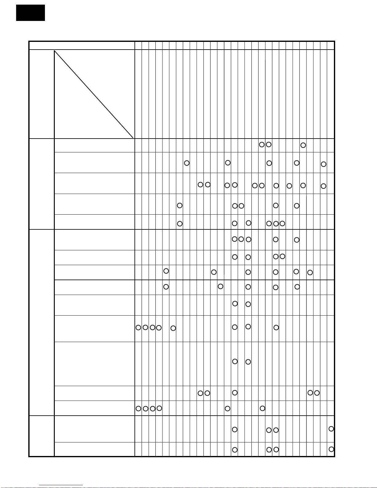
MEDIUM HIGH, MEDIUM, MEDIUM LOW, LOW
COOKING
When the microwave oven is preset for variable cooking
power, 230-240 volts A.C. power is supplied to the power
transformer intermittently within a 32-second time base
through the relay contact which is coupled with the current-
limiting relay. The following levels of microwave power are
given.
SETTING;
NOTE: TheON/OFFtimeratiodoesnotexactlycorrespond
to the percentage of microwave power, because
approx. 2 seconds are needed for heating up the
magnetron filament.
SENSOR COOKING CONDITION
UsingtheSENSORCOOKorSENSORINSTANTACTION
function, the foods are cooked or defrosted without figuring
time,powerlevelorquantity.Whentheovensensesenough
steam from the food, it relays the information to its micro-
processor which will calculate the remaining cooking time
and power level needed for best results.
When the food is cooked, water vapor is developed. The
32 sec. ON
24 sec. ON
18 sec. ON
12 sec. ON
6 sec. ON
8 sec. OFF
14 sec. OFF
20 sec. OFF
26 sec. OFF
HIGH
MEDIUM HIGH
MEDIUM
MEDIUM LOW
LOW
Approx. 70%
Approx. 50%
Approx. 30%
Approx. 10%

R-3H57
5
sensor “senses” the vapor and its resistance increases
gradually. When the resistance reaches the value set ac-
cording to the menu, supplementary cooking is started.
Thetimeofsupplementarycookingisdeterminedbyexperi-
ment with each food category and inputted into the LSI.
An example of how sensor works:
NOTE: The oven should not be operated on SENSOR
COOK orSENSORINSTANTACTIONimmediately
after plugging in the unit. Wait five minutes before
cookingonSENSORCOOKorSENSORINSTANT
ACTION.
2. Thecoilofshut-offrelay(RY-1)isenergized,theturntable
motor, oven lamp and cooling fan motor are turned on,
but the power transformer is not turned on.
3. After about 16 seconds, the cook relay (RY-2) is
energized. The power transformer is turned on,
microwaveenergyis producedandfirst stage isstarted.
The 16 seconds is the cooling time required to remove
any vapor from the oven cavity and sensor.
NOTE: Duringthisfirststage,donotopenthedoorortouch
STOP/CLEAR pad.
4. When the sensor detects the vapor emitted from the
food,thedisplayswitchesovertothe remaining cooking
time and the timer counts down to zero.
At this time, the door may be opened to stir food, turn it
or season, etc.
5. Whenthe timerreaches zero,an audible signal sounds.
The shut-off relay and cook relay are de-energized and
the power transformer, oven lamp, etc. are turned off.
6. OpeningthedoorortouchingtheSTOP/CLEARpad,the
timeofdaywill reappear onthedisplayandthe oven will
revert to an OFF condition.
DOOR OPEN MECHANISM
The door is opened by pushing the open button on the
control panel, refer to the Figure D-1.
Whentheopenbuttonispushed,theopenbuttonpushesup
theswitchlever,andthentheswitchleverpushesupthethe
latch head. The latch heads are moved upward and re-
leased from latch hook. Now the door will open.
LATCH
HEADS
LATCH HOOK
2ND. LATCH
SWITCH
MONITOR
SWITCH
SWITCH
LEVER
STOP SWITCH
1ST. LATCH
SWITCH
Figure D-1. Door Open Mechanism
1ST. LATCH SWITCH, 2ND. LATCH SWITCH AND
STOP SWITCH
1. When the oven door is closed, the contacts COM-NO)
must be closed.
2. Whentheovendoorisopened,thecontacts.(COM-NO)
must be opened.
MONITOR SWITCH
1. When the oven door is closed, the contacts (COM-NC)
must be opened.
2. When the oven door is opened, the contacts (COM-NC)
must be closed.
3. If the oven door is opened and the contacts (COM-NO)
ofthe 1st.latch switch and2nd. latchswitch failto open,
the fuse M8A blows simultaneously with closing the
contacts (COM-NC) of the monitor switch.
CAUTION: BEFORE REPLACING A BLOWN FUSE M8A
TESTTHE1ST.LATCHSWITCH, 2ND.LATCH
SWITCH MONITOR SWITCH AND MONITOR
RESISTOR FOR PROPER OPERATION.
MONITOR RESISTOR R 0.8Ω20W
The monitor resistor prevents the fuse M8A bursting when
the fuse M8A blows due to the operation of the monitor
switch.
1. Potatoesatroomtemperature.
Vapor is emitted very slowly.
2. Heat potatoes. Moisture and
humidityisemittedrapidly.You
can smell the aroma as it
cooks.
3. Sensor detects moisture and
humidity and calculates
cooking time and variable
power.
MICROWAVE
MICROWAVE
AH SENSOR
Cooking Sequence.
1. Touch each SENSOR COOK or SENSOR INSTANT
ACTION function pad to operating the sensor cooking.
FUNCTION OF IMPORTANT COMPONENTS

R-3H57
6
ASYMMETRIC RECTIFIER
Theasymmetricrectifierisasolidstatedevicethatprevents
currentflow inboth directions. Andit preventsthe tempera-
ture rise of the power transformer by blowing the fuse M8A
when the high voltage rectifier is shorted.
THERMAL CUT-OUT TC 145˚C (OVEN)
The thermal cut-out located on the top of the oven cavity is
designed to prevent damage to the oven if the foods in the
oven catch fire due to over heating produced by improper
setting of cook time or failure of control unit. Under normal
operation, the oven thermal cut-out remains closed. How-
ever, when abnormally high temperatures are reached
within the oven cavity, the oven thermal cut-out will open at
145˚C, causing the oven to shut down. The defective
thermal cut-out must be replace with new one.
THERMAL CUT-OUT 95˚C (FAN MOTOR)
Thethermalcut-outprotect the fanmotoragainstoverheat-
ing.Ifitstemperaturegoesuphigherthan95˚Cbecausethe
fanmotor islocked or theventilation operatingare blocked,
the contacts of the thermal cut-out will open and switch off
the oven. When the oven cools itself down to 75˚C, the
contacts of the thermal cut-out will close again.
TURNTABLE MOTOR
The turntable motor drives the turntable roller assembly to
rotate the turntable.
FAN MOTOR
The fan motor drives a blade which draws external cool air.
This cool air is directed through the air vanes surrounding
themagnetronandcoolsthemagnetron.Thisairischanneled
through the oven cavity to remove steam and vapors given
off from the heating foods. It is then exhausted through the
exhausting air vents at the oven cavity
NOISE FILTER (FOR NEW ZEALAND)
The noise filter prevents the radio frequency interference
that might flow back in the power circuit.
The rated peak reverse voltage of D1 of the asymmetric
rectifier is 6 KV The rated peak reverse voltage of D2 of the
asymmetricrectifieris1.7KV.D1andD2oftheasymmetric
rectifier or high voltage rectifier are shorted when the each
peak reverse voltage goes beyond the each rated peak
reverse voltage. (The process of blowing the fuse M8A.)
1. Thehighvoltagerectifierisshortedbyanycauseswhen
microwave cooking.
2. The peak reverse voltage of D2 of the rectifier goes
beyond the rated peak reverse voltage 1.7 KV in the
voltage doubler circuit.
3. D2 of the rectifier is shorted.
4. The large electric currents flow through the high voltage
winding of the power transformer.
5. ThelargeelectriccurrentsbeyondM8Aflowthroughthe
primary winding of the power transformer.
6. The fuse M8A blows by the large electric currents.
7. The power supply to the all electrical parts are cut off.
FUSE M8A
1. ThefuseM8Ablowswhenthecontacts(COM-NO)ofthe
1st.latchswitchand2nd.latchswitchremainclosedwith
theovendooropenandwhenthemonitorswitchcloses.
2. The fuse M8A also blows when asymmetric rectifier,
H.V. rectifier, H.V. wire harness, H.V.capacitor,
magnetronorsecondarywindingofpowertransformeris
shorted.
3. If the wire harness or electrical components are short-
circuited, this fuse M8A blows to prevent an electric
shock or fire hazard.
THERMAL CUT-OUT TC 145˚C (MG)
This thermal cut-out protects the magnetron against over-
heating. If the temperature goes up higher than 145˚C
because the fan motor is interrupted, the ventilation open-
ings are blocked, the thermal cut-out will open and the line
voltages to the power transformer will be cut off and the
operation of the magnetron will be stopped.
The defective thermal cut-out must be replaced with new
one.
D2 D1
ASYMMETRIC
RECTIFIER
HIGH VOLTAGE RECTIFIER
AB
C

R-3H57
7
SERVICING
WARNING TO SERVICE PERSONNEL
Microwave ovens contain circuitry capable of producing very high voltage and current, contact with any part of the
high voltage circuit will result in electrocution. High voltage capacitor, Power transformer, Magnetron, High voltage
rectifier assembly, High voltage harness.
REMEMBER TO CHECK 3D
1) Disconnect the supply.
2) Door opened, and wedged open.
3) Discharge high voltage capacitor.
WARNING: AGAINST THE CHARGE OF THE
HIGH-VOLTAGE CAPACITOR
The high-voltage capacitor remains charged about
60 seconds after the oven has been switched off.
Wait for 60 seconds and then short-circuit the con-
nection of the high-voltage capacitor (that is, of the
connectingleadofthe high-voltage rectifier)against
thechassiswiththe use ofaninsulatedscrewdriver.
Sharp recommend that wherever possible fault-finding
is carried out with the supply disconnected. It may in,
some cases, be necessary to connect the supply after
theoutercasehasbeenremoved,inthiseventcarryout
3D checks and then disconnect the leads to the primary
of the power transformer. Ensure that these leads re-
main isolated from other components and the oven
chassis. (Use insulation tape if necessary.) When the
testing is completed carry out 3D checks and reconnect
the leads to the primary of the power transformer.
REMEMBER TO CHECK 4R
1) Reconnectallleadsremovedfromcomponentsduring
testing.
2) Replace the outer case (cabinet).
3) Reconnect the supply.
4) Run the oven. Check all functions.
Microwave ovens should not be run empty. To test for
thepresenceof microwaveenergywithina cavity, place
acup ofcold water onthe oventurntable, close thedoor
andset themicrowavetimerfortwo(2)minutes.Setthe
powerlevel to HIGHandpush theSTARTbutton. When
the two minutes has elapsed (timer at zero) carefully
checkthatthewaterisnowhot.Ifthewaterremainscold
carry out 3D checks and re-examine the connections to
the component being tested.
Whenallserviceworkiscompleted,and the oven is fully assembled,themicrowavepoweroutputshouldbechecked
and microwave leakage test carried out
When troubleshooting the microwave oven, it is helpful to
follow the Sequence of Operation in performing the
checks. Many of the possible causes of trouble will require
that a specific test be performed. These tests are given a
procedure letter which will be found in the "Test
Procedure"section.
TROUBLESHOOTING GUIDE
IMPORTANT: Iftheovenbecomesinoperativebecauseof
a blown fuse M8A in the 1st. latch switch -
2nd. latch switch - monitor switch - monitor
resistor circuit, check the 1st. latch switch,
2nd.latchswitch,monitorswitchand moni-
tor resistor before replacing the fuse M8A.
.

R-3H57
8
Homefuseblowswhenpowersup-
plycordis plugged into wall outlet.
FUSE M8A blows when power
supply cord is plugged into wall
outlet.
Display does not show anything
whenpowersupplycordisplugged
into wall outlet.
Display doesnotoperateproperly
when STOP/CLEAR pad is
touched.
Oven lamp does not light at door
opened. (Display appears.)
Oven does not start when the
START pad is touched. (Display
appears)
Oven lamp does not light (Display
appears.)
Fan motor does not operate. (Dis-
play appears.)
Turntable motor assembly does
not operate. (Display appears.)
Oven or any electrical parts does
not stop when cooking time is 0 or
STOP/CLEAR pad is touched.
Oven seems to be operating but
littleornoheatisproducedinoven
load. (Microwave power level is
set at HIGH)
Oven does not seems to be oper-
ating properly when MEDIUM
HIGH, MEDIUM, MEDIUM LOW
or LOW is set. (Oven operates
properly at HIGH and then the
STOP/CLEAR pad is touched the
oven stops.)
Ovengoesintocookcyclebutshuts
down before end of cooking cycle.
Oven stops as soon as when the
START pad is touched.
AH sensor does not end during
Sensor Cooking condition. (Oven
does not shut off after a cup of
wateris boilingby sensorcooking.
Oven stops at 16 sec. after start-
ing.
OFF
CONDITION
PROBLEM
CONDITION
POSSIBLE CAUSE
AND
DEFECTIVE PARTS
TEST PROCEDURE
ON
CONDITION
MAGNETRON
POWER TRANSFORMER
H.V. RECTIFIER ASSEMBLY
HIGH VOLTAGE CAPACITOR
1ST. LATCH SWITCH
2ND. LATCH SWITCH
STOP SWITCH
MONITOR SWITCH
MONITOR RESISTOR
TEMPERATURE FUSE 95˚C
THERMAL CUT-OUT 145˚C
FAN MOTOR
TURNTABLE MOTOR
FUSE M8A
TOUCH CONTROL PANEL
KEY UNIT
RELAY (RY-1, RY-2)
FOIL PATERN ON P.W.B.
POWER SUPPLY CORD
SHORTED WIRE HARNESS
OPENED WIRE HARNESS
OVEN LAMP OR SOCKET
WALL OUTLET
MISADJUSTMENT SWITCH
HOME FUSE OR BREAKER
BLOCKED COOLING FAN
BLOCKED VENTILATION
NOISE FILTER (FOR N.Z.)
AH SENSOR
CK = Check / RE = Replace
ABC
D
EEEEGFFH HI JK LMRECK CKRECK CKCKCKCK NO
SENSOR
COOKING
CONDITION

R-3H57
9
TEST PROCEDURES
PROCEDURE
LETTER
CARRY OUT 3D CHECK.
Isolate the magnetron from high voltage circuit by removing all leads connected to filament terminal.
To test for an open circuit filament use an ohmmeter to make a continuity test between the magnetron
filament terminals, the meter should show a reading of less than 1 ohm.
To test for short filament to anode condition, connect ohmmeter between one of the filament terminals
and the case of the magnetron (ground). This test should be indicated an infinite resistance. If a low or
zero resistance reading is obtained then the magnetron should be replaced.
MICROWAVE OUTPUT POWER (1 Litre water load)
The following test procedure should be carried out with the microwave oven in a fully assembled
condition (outer case fitted). Microwave output power from the magnetron can be measured by way of
IEC 705, i.e. it can be measured by using water load how much it can be absorbed by the water load.
Tomeasurethemicrowaveoutputpower in themicrowave oven,therelationofcalorieandwattis used.
When P(W) heating works for t(second), approximately P x t/4.187 calorie is generated. On the other
hand, if the temperature of the water with V(ml) rises ∆T (°C) during this microwave heating period, the
calorie of the water is V x ∆T.
NEVER TOUCH ANY PART IN THE CIRCUIT WITH YOUR HAND OR AN INSULATED TOOL
WHILE THE OVEN IS IN OPERATION.
AMAGNETRON TEST
The formula is as follows;
P x t / 4.187 = V x ∆T P (W) = 4.187 x V x ∆T / t
Our condition for water load is as follows:
Room temperature..............around 20°C PowersupplyVoltage.........Ratedvoltage
Water load.........1000 g Initial temperature...........10±2°C Heating time.........47 sec.
P = 90 x ∆T
Measuring condition:
1. Container
The water container must be a cylindrical borosilicate glass vessel having a maximum material
thickness of 3 mm and an outside diameter of approximately 190 mm.
2. Temperature of the oven and vessel
The oven and the empty vessel are at ambient temperature prior to the start the test.
3. Temperature of the water
The initial temperature of the water is (10±2)°C.
4. Selectthe initial andfinal watertemperatureso thatthemaximum differencebetweenthe finalwater
temperature and the ambient temperature is 5˚C.
5. Select stirring devices and measuring instruments in order to minimize addition or removal of heat.
6. Thegraduationofthethermometermustbe scaled by 0.1°C at minimum andaccurate thermometer.
7. The water load must be (1000±5) g.
8. “t” is measured while the microwave generator is operating at full power. Magnetron filament heat-
up time is not included.
NOTE: The operation time of the microwave oven is “t + 2” sec. 2 sec. is magnetron filament heat-up time.
Measuring method:
1. Measure the initial temperature of the water before the water is added to the vessel.
(Example: The initial temperature T1 = 11°C)
2. Add the 1 litre water to the vessel.
3. Place the load on the centre of the shelf.
4. Operate the microwave oven at HIGH for the temperature of the water rises by a value ∆T of
(10 ±2)˚C.
5. Stir the water to equalize temperature throughout the vessel.
COMPONENT TEST

R-3H57
10
TEST PROCEDURES
PROCEDURE
LETTER COMPONENT TEST
6. Measure the final water temperature. (Example: The final temperature T2 = 21°C)
7. Calculate the microwave power output P in watts from above formula.
Initial temperature.................................................................................................. T1 = 11°C
Temperature after (47 + 2) = 49 sec...................................................................... T2 = 21°C
Temperature difference Cold-Warm .................................................................... ∆T1 = 10°C
Measured output power
The equation is “P = 90 x ∆T”....................................................... P = 90 x 10°C = 900 Watts
JUDGMENT: The measured output power should be at least ±15 % of the rated output power.
CAUTION: 1°C CORRESPONDS TO 90 WATTS REPEAT MEASUREMENT IF THE POWER IS
INSUFFICIENT.
1000g
1000g
1000g
T1˚C T2˚C
Heat up for49 sec.
MICROWAVE OUTPUT POWER (2 Litre water load)
The following test procedure should be carried out with the microwave oven in a fully assembled
condition (with outer case fitted).
Microwave output power from the magnetron can be measured by way of substitution, i.e. it can be
measured by using a water load how much it can be absorbed by the water load. To measure the
microwave output power in the microwave oven, the relation of calorie and watt is used.
Ontheotherhand,ifthetemperature of the waterwith V(ml)rises∆T(˚C)duringthis microwave heating
period, the calorie of the water is V x ∆T.
The formula is as follows;
P = 8330 x ∆T/t
Our condition for water load is as follows:
Room temperature ................. 23±2˚C Power supply Voltage............. Rated voltage
Water load...... 2000 ml Initial temperature ......23±1˚C Heating time...... 1 min. 51sec.
P = 75 x ∆T
Measuring method:
A) The two water containers must be prepared.
Thewatercontainermustbeone(1)litrebeakermadeofPyrex glassanditsdiameterapproximately
12cm.
B) Putthe one (1)litre water intoeachbeaker (Eachbeakerhas onelitrewater). Theinitialtemperature
of the water should be 23±1˚C.
C) Mark T1 on the one beaker and mark T2 on the other one. And stir the water and measure the
temperature of water the thermometer and note them. The graduation of the thermometer must be
scaled by 0.1˚C at minimum and an accurate mercury thermometer is recommended.
D) Place the two (2) beakers as touching each other in the centre of the oven cavity.
E) Set the timer to 1 minutes and 51 seconds, start the oven at 100% power.
F) The time must be measured with stopwatch or wristwatch.
G) After 1 minutes and 51 seconds, stop the oven by opening the door.
H) Put the two (2) beakers out of the oven cavity and measure the temperature of the water by stirring
the water with thermometer and note them.

R-3H57
11
TEST PROCEDURES (CONT'D)
BPOWER TRANSFORMER TEST
WARNING: Highvoltagesandlargecurrentsarepresentatthesecondarywindingandfilament
winding of the power transformer. It is very dangerous to work near this part when
the oven is on. NEVER make any voltage measurements of the high-voltage
circuits, including the magnetron filament.
CARRY OUT 3D CHECKS.
Disconnect the leads to the primary winding of the power transformer. Disconnect the filament and
secondarywindingconnectionsfromtherestoftheHVcircuitry.Usinganohmmeter,setonalowrange,
it is possible to check the continuity of all three windings. The following readings should be obtained:
a. Primary winding ................... approx. 1.4 Ω
b. Secondary winding............... approx. 98 Ω
c. Filament winding .................. less than 1Ω
Ifthereadingobtainedarenotstatedasabove,thenthepowertransformerisprobablyfaultyandshould
be replaced.
CARRY OUT 4R CHECKS.
C HIGH VOLTAGE RECTIFIER ASSEMBLY TEST
HIGH VOLTAGE RECTIFIER TEST
CARRY OUT 3D CHECKS.
Isolate the high voltage rectifier assembly from the HV circuit. The high voltage rectifier can be tested
using an ohmmeter set to its highest range. Connect the ohmmeter across the terminal B+C of the high
voltage rectifier and note the reading obtained. Reverse the meter leads and note this second reading.
The normal resistance is infinite in one direction and more than 100 kΩin the other direction.
Example
Initial temperature .............................................................................T1 = 23˚C T2 = 24˚C
Temperature after 1 min. 51 sec. ..................................................... T1 = 33˚C T2 = 34˚C
Temperature difference Cold-Warm.............................................. ∆T1 = 10˚C ∆T2 = 10˚C
Mean temperature rise ∆T......................... ∆T = (∆T1 ±∆T2) / 2 = (10˚C+10˚C) / 2 = 10˚C
Measured output power
The equation is P= 75 x ∆T ........................................................ P= 75 x 10˚C = 750 Watts
NOTE: The measured output power should be at least ±15 % of the rated output power.
CAUTION: 1˚C CORRESPONDS TO 75 WATTS. REPEAT MEASUREMENT IF THE POWER IS
INSUFFICIENT.
COMPONENT TEST
PROCEDURE
LETTER
1 l 1 l
(T1 C) (T2 C)
1 l 1 l
(T1 C) (T2 C)
Heat up for 1min. 51 sec.

R-3H57
12
TEST PROCEDURES (CONT'D)
CARRY OUT 4R CHECKS.
ASYMMETRIC RECTIFIER TEST
CARRY OUT 3D CHECKS.
Isolate the high voltage rectifier assembly from the HV circuit. The asymmetric can be tested using an
ohmmeter set to its highest range across the terminals A+B of the asymmetric rectifier and note the
reading obtained. Reverse the meter leads and note this second reading. If an open circuit is indicated
in both direction then the asymmetric rectifier is good. If an asymmetric rectifier is shorted in either
direction,thentheasymmetricrectifierisprobablyfaultyandmustbereplacedwithhighvoltagerectifier.
Whentheasymmetricrectifierisdefective,checkwhethermagnetron,highvoltagerectifier,highvoltage
wire or filament winding of the power transformer is shorted.
CARRY OUT 4R CHECKS.
NOTE: FOR MEASUREMENT OF THE RESISTANCE OF THE RECTIFIER, THE BATTERIES OF THE
MEASURING INSTRUMENT MUST HAVE A VOLTAGE AT LEAST 6 VOLTS, BECAUSE
OTHERWISE AN INFINITE RESISTANCE MIGHT BE SHOWN IN BOTH DIRECTIONS.
PROCEDURE
LETTER COMPONENT TEST
AB
C
D2 D1
ASYMMETRIC
RECTIFIER
HIGH VOLTAGE RECTIFIER
D HIGH VOLTAGE CAPACITOR TEST
CARRY OUT 3D CHECKS.
A. Isolate the high voltage capacitor from the circuit.
B. Continuity check must be carried out with measuring instrument which is set to the highest resistance
range.
C. Anormalcapacitorshowscontinuityforashorttime(kick)andthenaresistanceofabout10MΩafterithas
been charged.
D. A short-circuited capacitor shows continuity all the time.
E. An open capacitor constantly shows a resistance about 10 MΩbecause of its internal 10MΩresistance.
F. When the internal wire is opened in the high voltage capacitor shows an infinite resistance.
G. The resistance across all the terminals and the chassis must be infinite when the capacitor is normal.
If incorrect reading are obtained, the high voltage capacitor must be replaced.
CARRY OUT 4R CHECKS.
ESWITCH TEST
CARRY OUT 3D CHECKS.
Isolate the switch to be tested and using an ohmmeter check between the terminals as described in the
following table. Table: Terminal Connection of Switch
Plunger Operation COM to NO COM to NC
Released O.C. S.C.
Depressed S.C. O.C.
COM; Common terminal,
NO; Normally open terminal
NC; Normally close terminal
S.C.; Short,
O.C.; Open circuit
If incorrect readings are obtained, make the necessary switch adjustment or replace the switch.
CARRY OUT 4R CHECKS.
ETHERMAL CUT-OUT TEST
CARRY OUT 3D CHECKS.
Disconnect the leads from the terminals of the thermal cut-out. Then using an ohmmeter, make a
continuity test across the two terminals as described in the table below.
CARRY OUT 4R CHECKS .Table: Thermal cut-out Test
Temperature of "ON" condition Temperature of "OFF" condition Indication ofohmmeter
Parts Name (closed circuit) (˚C) (open circuit) (˚C) (When room temperature
is approx. 20˚C)
Thermal cut-out 145˚C This is not resetable type Above 145˚C Closed circuit.
Thermal cut-out 95˚C Below 75˚C Above 95˚C Closed circuit.

R-3H57
13
PROCEDURE
LETTER COMPONENT TEST
TEST PROCEDURES (CONT'D)
If incorrect readings are obtained, replace the thermal cut-out.
An open circuit thermal cut-out 145˚C (MG) indicates that the magnetron has overheated, this may be
due to resistricted ventilation, cooling fan failure or a fault condition within the magnetron or HV circuit.
An open circuit thermal cut-out 145˚C (OVEN) indicates that the foods in the oven may catch fire, this
may be due to over heating produced by improper setting of the cooking time or failure of the control
panel.
An open circuit thermal cut-out 95˚C (FAN) indicates that the fan motor winding has overheated, this
may be due to blocked ventilation or locked cooling fan.
CARRY OUT 3D CHECKS.
Disconnecttheleadsfromthemonitorresist.Usinganohmmeterandsetonalowrange.Checkbetween
the terminals of the monitor resistor.
The resistance of monitor resistor is approx. 0.8 ohms.
If incorrect readings are obtained, replace the monitor resistor.
CARRY OUT 4R CHECKS.
G MONITOR RESISTOR TEST
CARRY OUT 3D CHECKS.
Disconnect the leads from the motor.
Using an ohmmeter, check the resistance between the two terminals as described in the table below.
HMOTOR WINDING TEST
Table: Resistance of Motor
Motors Resistance
Fan motor Approximately 370 Ω
Turntable motor Approximately 16.08 kΩ
If incorrect readings are obtained, replace the motor. CARRY OUT 4R CHECKS
IBLOWN FUSE F M8A
CARRY OUT 3D CHECKS.
1. If the fuse M8A is blown, there could be shorts or ground in electrical parts or wire harness.
Check them and replace the defective parts or repair the wire harness.
2. If the fuse M8A is blown when the door is opened, check the 2nd. latch switch, monitor switch and
monitor resistor.
IfthefuseM8Aisblownbyincorrectdoorswitchingreplacethedefectiveswitch(s)andthefuseM8A.
3. Ifthe fuseM8A isblown, therecould bea shortin the asymmetric rectifier or there couldbe aground
in wire harness. A short in the asymmetric rectifier may have occured due to short or ground in H.V.
rectifier, magnetron, power transformer or H.V. wire. Check them and replace the defective parts or
repair the wire harness.
CARRY OUT 4R CHECKS.
CAUTION: ONLY REPLACE FUSE M8A WITH THE CORRECT VALUE REPLACEMENT
J TOUCH CONTROL PANEL ASSEMBLY TEST
The touch control panel consists of circuits including semiconductors such as LSI, ICs, etc. Therefore,
unlike conventional microwave ovens, proper maintenance cannot be performed with only a voltmeter
andohmmeter.Inthisservicemanual,thetouchcontrolpanelassemblyisdivided intotwounits,Control
Unit and Key Unit.

R-3H57
14
TEST PROCEDURES (CONT'D)
PROCEDURE
LETTER COMPONENT TEST
1. Key Unit
The following symptoms indicate a defective key unit. Replace the key unit.
a) When touching the pads, a certain pad produces no signal at all.
b) When touching a number pad, two figures or more are displayed.
c) When touching the pads, sometimes a pad produces no signal.
2. Control Panel.
The following symptoms indicate a defective control unit. Replace the control unit.
2-1 In connection with pads.
a) When touching the pads, a certain group of pads do not produce a signal.
b) When touching the pads, no pads produce a signal.
2-2 In connection with indicators.
a) At a certain digit, all or some segments do not light up.
b) At a certain digit, brightness is low.
c) Only one indicator does not light.
d) The corresponding segments of all digits do not light up; or they continue to light up.
e) Wrong figure appears.
f) A certain group of indicators do not light up.
g) The figure of all digits flicker.
2-3 Other possible problems caused by defective control unit.
a) Buzzer does not sound or continues to sound.
b) Clock does not operate properly.
c) Cooking is not possible.
d) Proper temperature measurement is not obtained.
K KEY UNIT TEST
If the display fails to clear when the STOP/CLEAR pad is depressed, first verify the flat ribbon is making
goodcontact,verifythatthedoorsensingswitch(stopswitch)operates properly; that is thecontacts are
closed when the door is closed and open when the door is open.
If the door sensing switch (stop switch) is good, disconnect the flat ribbon that connects the key unit to
the control unit and make sure the door sensing switch is closed (either close the door or short the door
sensing switch connector). Use the key unit matrix indicated on the control panel schematic and place
a jumper wire between the pins that correspond to the STOP/CLEAR pad making momentary contact.
Ifthecontrolunitrespondsbyclearingwithabeepthekeyunitisfaultyandmustbereplaced.Ifthecontrol
unit does not respond, it is faulty and must be replaced.
If a specific pad does not respond, the above method may be used (after clearing the control unit) to
determine if the control unit or key pad is at fault.
KEY UNIT
STOP
CLEAR
POWER
LEVEL
G12
G11
G10
G9
G8 G7 G6 G5 G4 G3 G2 G1
DESSERTS
Jacket
Potato
LESS
MORE
1
2345
6
7
890
REHEAT HELP TIMER
MEAT
CLOCK
MEMORY
1
MEMORY
2
Fish
Fillets
AUTO
START
RICE
PASTA
EASY
DEFROST
VEGE-
TABLES
Fresh
Vegetables
Reheat
Beverage
INSTANT
COOK
START

R-3H57
15
TEST PROCEDURES (CONT'D)
PROCEDURE
LETTER COMPONENT TEST
L RELAY TEST
CARRY OUT 3D CHECKS.
Remove the outer case and check voltage between Pin Nos. 3 and 5 of the 3-pin connector (A) on the
control unit with an A.C. voltmeter. The meter should indicate 230~240 volts, if not check oven circuit.
RY1 and RY2 Relay Test
Check voltage at the relay coil with a D.C. voltmeter during the microwave cooking operation.
DC. voltage indicated ............... Defective relay.
DC. voltage not indicated ......... Check diode which is connected to the relay coil. If diode is good,
control unit is defective.
RELAY SYMBOL OPERATIONAL VOLTAGE CONNECTED COMPONENTS
RY1 APPROX. 24.5V D.C. Oven lamp / Turntable motor / Cooling fan motor
RY2 APPROX. 24.0V D.C. Power transformer
CARRY OUT 4R CHECKS.
M PROCEDURES TO BE TAKEN WHEN THE FOIL PATTERN ON THE PRINTED WIRING BOARD
(PWB) IS OPEN.
To protect the electronic circuits, this model is provided with a fine foil pattern added to the primary on
thePWB, this foilpattern acts asafuse. Ifthefoil patternisopen, followthetroubleshooting guide given
below for repair.
Problem: POWER ON, indicator does not light up.
CARRY OUT 3D CHECKS.
STEPS OCCURANCE CAUSE OR CORRECTION
1 The rated AC voltage is not present at Check supply voltage and oven power cord.
POWER terminal of CPU connector (CN-A)
2 The rated AC voltage is present at primary Low voltage transformer or secondary circuit defective.
side of low voltage transformer. Check and repair.
3 Only pattern at "a" is broken. *Insert jumper wire J1 and solder.
(CARRY OUT 3D CHECKS BEFORE REPAIR)
4 Pattern at "a" and "b" are broken. *Insert the coil RCILF2003YAZZ between "c" and "d".
(CARRY OUT 3D CHECKS BEFORE REPAIR)
NOTE: *At the time of making these repairs,
make a visual inspection of the varistor.
check for burned damage and examine
thetransformerwithanohmmeterforthe
presence of layer short-circuit (check
primary coil resistance). If any abnormal
condition is detected, replace the
defective parts.
CARRY OUT 4R CHECKS.
RY2
VRS1
38
(J1)
XH
3
(J8)
a
b
cd

R-3H57
16
TEST PROCEDURES (CONT'D)
PROCEDURE
LETTER COMPONENT TEST
L (min) Cx ±20% Cy ±20%
1.0 mH 0.068µF 0.0022µF
N
LC
L
L
C
WHT
RED
XY
MEASURING POINT INDICATION OF OHMMETER
Between N and L Open circuit
Between terminal N and WHITE Short circuit
Between terminal L and RED Short circuit
If incorrect readings are obtained, replace the noise filter unit.
CARRY OUT 4R CHECKS.
N NOISE FILTER TEST
CARRY OUT 3D CHECKS.
Disconnect the leads from the terminals of the noise
filter.Usinganohmmeter,check between theterminals
as described in the following table.
OAH SENSOR TEST
Checking the initial sensor cooking condition
(1) The oven should be plugged in at least five minutes before sensor cooking.
(2) Room temperature should not exceed 35˚C.
(3) The unit should not be installed in any area where heat and steam are generated. The unit should
not be installed, for example, next to a conventional surface unit. Refer to the "INSTALLATION
Instructions" .
(4) Exhaust vents are provided on the back of the unit for proper cooling and air flow in the cavity. To
permit adequate ventilation, be sure to install so as not to block these vents. There should be some
space for air circulation.
(5)Besuretheexteriorofthecookingcontainerandtheinterioroftheovenaredry.Wipeoffanymoisture
with a dry cloth or paper towel.
(6) The Sensor works with food at normal storage temperature.For example, chicken pieces would be
at refrigerator temperature and canned soup at room temperature.
(7) Avoid using aerosol sprays or cleaning solvents near the oven while using Sensor settings. The
sensor will detect the vapour given of by the spray and turn off before food is properly cooked.
(8) If the sensor has not detected the vapour of the food, ERROR will appear and the oven will shut off.
Water load cooking test
Make sure the oven has been plugged in at least five minutes before checking sensor cook operation.
The cabinet should be installed and screws tightened.
(1) Fill approximately 200 milliliters (7.2 oz) of tap water in a 1000 milliliter measuring cup.
(2) Place the container on the center of tray in the oven cavity.
(3) Close the door.
(4) Touch Reheat Beverage pad of SENSOR INSTANT ACTION once. Now, the oven is in the sensor
cooking condition and "REHEAT", "BEVE", "RAGE" and "SENSOR" will appear in the display.
(5) The oven will operate for the first 16 seconds, without generating microwave energy.
NOTE: ERROR will appear if the door is opend or STOP/CLEAR pad is touched during first stage of
sensor cooking.
(6) After approximately 16 seconds, microwave energy is produced, oven should turn off after water is
boiling (bubling).
If the oven does not turn off, replace the AH sensor or check the control unit, refer to explanation below.
TESTING METHOD FOR AH SENSOR AND/OR CONTROL UNIT
To determine if the sensor is defective, the simplest method is to replace it with a new replacement
sensor.

R-3H57
17
TEST PROCEDURES (CONT'D)
PROCEDURE
LETTER COMPONENT TEST
(1) Disconnect oven from power supply and remove outer case.
(2) Discharge the high voltage capacitor.
(3) Remove the AH sensor.
(4) Install the new AH sensor.
(5) Re-install the outer case.
(6) Reconnect the oven to the power supply and check the sensor cook operation proceed as follows:
6-1. Fill approximately 200 milliliters (7.2 oz) of tap water in a 1000 milliliter measuring cup.
6-2. Place the container on the center of tray in the oven cavity.
6-3. Close the door.
6-4. Touch Reheat Beverage pad once.
6-5. The control panel is in automatic Sensor operation.
6-6. The oven will turn off automatically after the water is boiling (bubling).
If new sensor dose not operate properly, the problem is with the control unit.
CHECKING CONTROL UNIT
(1) Disconnect oven from power supply and remove outer case.
(2) Discharge the high voltage capacitor.
(3) Disconnect the wire leads from the cook relay.
(4) Disconnect the sensor connector that is mounted to lower portion of control panel.
(5) Then connect the dummy resistor circuit (see fig.) to the sensor connector of control panel.
(6) Reconnect the oven to the power supply and check the sensor cook operation, proceed as follows:
6-1. Touch Reheat Beverage pad once.
6-2. The control panel is in the sensor cooking operation.
6-3. After approximately 20 seconds, push plunger of select switch. This condition is same as
judgement by AH sensor.
6-4. After approximately 3 seconds, cooking operation turns off, an audible signal will sound,
and the display will then revert to the time of day.
If the above is not the case, the control unit is probably defective.
If the above is proper, the AH sensor is probably defective.
R1,R2 : 22Ω±1% 1/2W
R3 : 10kΩ±5% 1/4W
R4 : 1MΩ±5% 1/4W
Sensor Dummy Resistor Circuit
Plunger
NC
NO
COM
COM NO
NC
R3 R4
R1
R2
1
2
3
F-1
F-2
F-3
To connector (F)
on Control Unit.
CONNECTOR

18
R-3H57
The touch control section consists of the following units
as shown in the touch control panel circuit.
(1) Key Unit
(2) Control Unit
The principal functions of these units and the signals com-
municated among them are explained below.
Key Unit
The key unit is composed of a matrix, signals generated in
the LSI are sent to the key unit through P40-P46 and P57.
When a key pad is touched, a signal is completed through
thekeyunitandpassedbackto the LSI throughP70-P73 to
perform the function that was requested.
Control Unit
Control unit consists of LSI, power source circuit, synchro-
nizing signal circuit, ACL circuit, buzzer circuit, absolute
humidity sensor circuit and indicator circuit.
1) LSI
This LSI controls the absolute humidity sensor signal,
key strobe signal, relay driving signal for oven function
and indicator signal.
2) Power Source Circuit
This circuit generates voltages necessary in the control
unit.
Symbol Voltage Application
VC -5.2V LSI(IC1), ACL circuit
VP -31V Fluorescent display tube : Grid
and anode voltage
VF1 2.2Vac Filament of fluorescent display
tube
VF2 (VF1 to VF2 voltage)
TOUCH CONTROL PANEL ASSEMBLY
OUTLINE OF TOUCH CONTROL PANEL
3) Synchronizing Signal Circuit
The power source synchronizing signal is available in
order to compose a basic standard time in the clock
circuit.Itincorporatesaverysmallerrorbecauseitworks
on commercial frequency.
4) ACL Circuit
A circuit to generate a signals which resetting the LSI to
the initial state when power is supplied.
5) Buzzer Circuit
The buzzer is responds to signals from the LSI to emit
audiblesounds(keytouchsoundandcompletionsound).
6) Absolute Humidity Sensor Circuit
This circuit detects moisture of a food which is cooking
to allow its automatic cooking.
7) Stop Switch
A switch to "tell" the LSI if the door is open or closed.
8) Relay Circuit
To drive the magnetron, fan motor, turntable motor and
light the oven lamp.
9) Indicator Circuit
Indicator element is a Fluorescent Display.
Basically, a Fluorescent Display is triode having a
cathode, a grid and an anode. Usually, the cathode of a
Fluorescent Display is directly heated and the filament
serves as cathode.
The Fluorescent Display has 7-digits, 15-segments are
used for displaying figures.
Table of contents
Other Sharp Microwave Oven manuals

Sharp
Sharp R-970 Instruction Manual

Sharp
Sharp R-6471L User manual

Sharp
Sharp R-350D User manual

Sharp
Sharp Carousel R-1850A User manual

Sharp
Sharp Carousel II R-3A84 User manual

Sharp
Sharp R-340H Use and care manual

Sharp
Sharp SMD2499FS Instruction Manual

Sharp
Sharp R-3S68 User manual

Sharp
Sharp R-842IN User manual

Sharp
Sharp R-234W User manual

Sharp
Sharp Carousel R-1510 User manual

Sharp
Sharp R-393 User manual

Sharp
Sharp R-319FW User manual

Sharp
Sharp R-880D Use and care manual

Sharp
Sharp R-242E User manual

Sharp
Sharp R-3731 User manual

Sharp
Sharp YC-MG02E-S User manual

Sharp
Sharp R-343M Instruction Manual

Sharp
Sharp R-279T Technical specifications

Sharp
Sharp Microwave Drawer SMD2440JS User manual