manuals.online logo
Brands
  1. Home
  2. •
  3. Brands
  4. •
  5. Sharp
  6. •
  7. Microwave Oven
  8. •
  9. Sharp R-6280 User manual

Sharp R-6280 User manual

Other Sharp Microwave Oven manuals

Sharp R-398E User manual

Sharp

Sharp R-398E User manual

Sharp R-842IN User manual

Sharp

Sharp R-842IN User manual

Sharp YC-PC254A User manual

Sharp

Sharp YC-PC254A User manual

Sharp CD1800M User manual

Sharp

Sharp CD1800M User manual

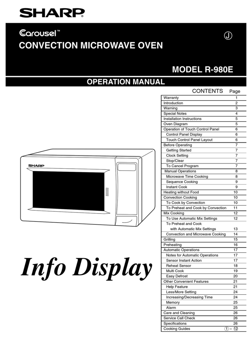
Sharp Carousel R-980E User manual

Sharp

Sharp Carousel R-980E User manual

Sharp R-922STM User manual

Sharp

Sharp R-922STM User manual

Sharp R8-A User manual

Sharp

Sharp R8-A User manual

Sharp R-793M User manual

Sharp

Sharp R-793M User manual

Sharp R-793M Instruction Manual

Sharp

Sharp R-793M Instruction Manual

Sharp R-342H User manual

Sharp

Sharp R-342H User manual

Sharp R-345M Instruction Manual

Sharp

Sharp R-345M Instruction Manual

Sharp YC-PC322A User manual

Sharp

Sharp YC-PC322A User manual

Sharp Carousel SMO1652DS User manual

Sharp

Sharp Carousel SMO1652DS User manual

Sharp R-1490 User manual

Sharp

Sharp R-1490 User manual

Sharp Carousel R-1200 Specification sheet

Sharp

Sharp Carousel R-1200 Specification sheet

Sharp R642BKW User manual

Sharp

Sharp R642BKW User manual

Sharp R-891M User manual

Sharp

Sharp R-891M User manual

Sharp R-204EWA User manual

Sharp

Sharp R-204EWA User manual

Sharp Microwave Drawer SMD2489ES User manual

Sharp

Sharp Microwave Drawer SMD2489ES User manual

Sharp Carousel R-890N User manual

Sharp

Sharp Carousel R-890N User manual

Sharp R-360EG User manual

Sharp

Sharp R-360EG User manual

Sharp R-207 Instruction Manual

Sharp

Sharp R-207 Instruction Manual

Sharp R-509FW Owner's manual

Sharp

Sharp R-509FW Owner's manual

Sharp R842SLM User manual

Sharp

Sharp R842SLM User manual

Popular Microwave Oven manuals by other brands

PROFILO MD1000 instruction manual

PROFILO

PROFILO MD1000 instruction manual

Candy MIC 201 EX User instructions

Candy

Candy MIC 201 EX User instructions

PITSOS GMW3101B user manual

PITSOS

PITSOS GMW3101B user manual

Sears 5648744780 Use & care manual

Sears

Sears 5648744780 Use & care manual

BOMANN CB 1272 Instruction manual & guarantee

BOMANN

BOMANN CB 1272 Instruction manual & guarantee

Conrad Electronic 2372935 operating instructions

Conrad Electronic

Conrad Electronic 2372935 operating instructions

GE Spacemaker JVM1440BH datasheet

GE

GE Spacemaker JVM1440BH datasheet

DAEWOO ELECTRONICS KOR-6L8K5S83 Operating instructions & cook book

DAEWOO ELECTRONICS

DAEWOO ELECTRONICS KOR-6L8K5S83 Operating instructions & cook book

DAEWOO ELECTRONICS KOR-1N5A9S Operating instructions & cook book

DAEWOO ELECTRONICS

DAEWOO ELECTRONICS KOR-1N5A9S Operating instructions & cook book

Daewoo KQG-6617G Operating instructions & cook book

Daewoo

Daewoo KQG-6617G Operating instructions & cook book

Samsung M1779 Owner's instructions

Samsung

Samsung M1779 Owner's instructions

GE JES1143 Use and care & cooking guide

GE

GE JES1143 Use and care & cooking guide

Miele H6200BM(TB) Operating and installation instructions

Miele

Miele H6200BM(TB) Operating and installation instructions

Jocel JMO011480 instruction manual

Jocel

Jocel JMO011480 instruction manual

Electrolux EVL8E00X user manual

Electrolux

Electrolux EVL8E00X user manual

STOVES Q900GRF DO User, installation & servicing instructions

STOVES

STOVES Q900GRF DO User, installation & servicing instructions

Daewoo KOR-6L0B3S Operating instructions & cook book

Daewoo

Daewoo KOR-6L0B3S Operating instructions & cook book

KitchenAid KCMS1555 Use and care guide

KitchenAid

KitchenAid KCMS1555 Use and care guide

manuals.online logo
manuals.online logoBrands
  • About & Mission
  • Contact us
  • Privacy Policy
  • Terms and Conditions

Copyright 2025 Manuals.Online. All Rights Reserved.

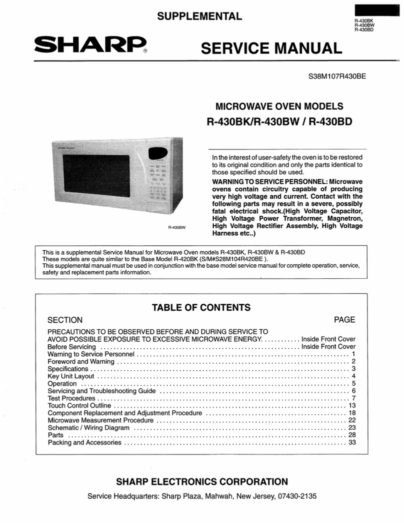
R -6280
SHARP SERVICE MANUAL
S3702R6280J//
MICROWAVE OVEN
In the interests of user-safety the set should be restored IO its ongina!
condition and only parts identical to those specified should be zsm
TABLE OF CONTENTS Page
FOREWORD ,....................,............I......................~....................~..............................................................,.....,... 1
CAUTION, MICROWAVE RADIATION ....................................~...........................................................~........ 1
PRODUCT DESCRIPTION ,..,.,...,,..................................,.~..........~...,...,..,.,...,.......,,.,..................,.........,..,......,, 2
OPERATION ..........................*............................................................................................................................ 3
SERVICING ..........~....................~............~.........................~.....................~...........................................................
COMPONENT REPLACEMENT AND ADJUSTMENT PROCEDURES
MICROWAVE MEASUREMENT ................................................... 1;
PROCEDURE .......................................................................................... 16
PICTORIAL DIAGRAM AND SCHEMATIC DIAGRAM .......................................(..,..,......,...........,..,...,.. 17
PARTS LIST .................................................................................................................................................... 18
PACKING AND ACCESSORIES ,..~...........................,..................~.......,,......,,...,.......,........,,..,.....,..~............. 22
SHARPCORPORATION
R -6280
R-6280
SERVICE MANUAL
SHARP
MICROWAVE OVEN
R-6280
FOREWORD
This Manual has been prepared to provide Sharp Corp. Service
Personnel with complete Operation and Service Information for
the SHARP MICROWAVE oven, R-6280.
It is recommended that service personnel carefully study the
entire text of this manual so they will be qualified to render
satisfactory customer service.
Check interlock switches and door seal carefully. Special at-
tention should be given to avoid electrical snack and microwave
radiation hazard.
CAUTION
MICRQWAVE RADIAfiON
Personnel should not be exposed to the microwave energy
which may radiate from the magnetron or other microwave
generating devices if it is improperly used or connected. All
input and output microwave connections, waveguides,flanges
and gaskets must be secured. Never operate the device without
a microwave energy abs’orbing load attached. Never look into
an open waveguide or antenna while the device is energized.
OSAKA, JAPAN
PRODUCT DESCRIPTION
R -6280
PRODUCTION DESCRIPTION
EXPLANATION OF MICROWAVE COOKING
The Sharp Microwave Oven uses microwave energy to
produce heat in the food to be cooked. Unlike con-
ventional ovens microwave energy will cook foods
without applying external heat.
Microwaves, which are short electromagnetic waves
of RF (radio frequency) energy, pass through materials
such as glass, paper, china and most plastics. Materi-
als such as metal and aluminum foil tend to reflect
microwaves and may be used only as recommended in
the cooking instructions. Materials with a high
moisture content, like most foods, will absorb micro-
wave energy. As the microwave energy at a frequency
of 2450 Megahertz enters the food, the molecules align
themselves with the energy. Because the microwaves
are changing polarity every half cycle, the food mole-
cules are changing direction every half cycle or oscil-
lating back and forth 4,900,000,000 times per second.
This high speed oscillation causes friction between the
molecules, thereby converting the microwave energy
to heat.
SPECIFICATION
ITEM DESCRIPTION
Power Requirements / -240 Volts
! 50 Hertz
: Single phase, 3 wire earthed
Power Consumption
Power Output
Case Dimensions
---
Cookrng Cavity Dimensions
--
Control Complement
Set Weight
1 13oow
i 650 watts normal of RF microwave energy (2 liter water load)
Operating frequency of 2450MHz .
/ Width 520 mm
! Height 318 mm including foot
j Depth 393 mm
Width 345 mm
Height 217 mm
Depth 364 mm
60 min. Dual Speed Timer
Microwave Power for Variabie Cooking
Repetition Rate;
HIGH ...............~...............
M ED H1GH Full power throughout the cooking time
............................................ approx. 70% of Full Power
MED .................................I..................... approx. 50% of Full Power
MED LOW DEFROST ........................ approx. 30% of Full Power
LOW ....................................................... approx. 10% of Full Power
Ac>r>rox. 17.5 kg
R-6280
OPERATION
NORMAL COOKING SEQUENCE
To start cooking:
1.
2
3
4
Place the food to be cooked in the oven and close the door
firmly.
Set the cooking control for a desired position.
Set the timer for a desired cooking time. The oven lamp
will come on immediately.
Push the cook button. The turntable motor will rotate to
indicate the oven is in the cook cycle, and the timer motor
will operate.
5.
Note: If the oven door IS opened during the cook cycle,
the oven will go out of the cook cycle (no microwave
energy) and the timer will stop. This is done so the exact
cooking time remains on the timer. To restore cooking
operation, the door must be closed and the cook button
must be pushed again.
At the end of the cook cycle (time returned to ” 0 “), the
timer bell will ring. The oven will stop supplying the
microwave energy.
DESCRIPTION OF OPERATING SEQUENCE
The following is a complete descrrption of component func-
tions during the three stages of oven operation.
OFF CONDlTiON
With the timer dial at ” 0 ” position and the door closed, no
components in the oven will operate (Figure O-l). But rhe
oven lamp will come on with the door opened.
IDLE CONDITION
Closing the door activates latch switch. Selecting a cooking
time closes the timer contacts leading to the oven lamp and
latch switch, therefore the oven lamp comes on (Figure O-2).
COOKiNG CONDITION
1. FULL POWER COOKING
When the cooking control set to HIGH position and the
start button is pushed ,with the timer set, the following
operation occurs: (Figure O-3).
l-l. Timer motor, turntable motor and fan motor are
energized.
l-2. The 240 volts A.C. is supplied to a primary winding
of the power transformer through the vari-switch, and
is converts 3.5 volts A.C. output on the filament
winding and approximately 1,900 volts A.C. on the
high voltage winding.
1-3. The filament winding voltage heats the magnetron
filament and H.V winding voltage is sent to voltage
doubler circuit consisting of a high voltage capacitor
and a rectifier.
l-4. The microwave energy produced by the magnetron
tube is channeled into the oven cavity where the food
is placed to be cooked.
1-5. Upon completion of the selected cooking time, the
timer contacg open and the oven reverts to the off
condition.
in the case cook (latch) switch falls with its contacts closed
when the door is opened, the monitor switch wrll form a
short circuit through the fuse and the cook (latch! switch.
2. VARIABLE COOKING
When the cooking control set to MED HIGH, MED, MED
LOW DEFROST, LOW position and the cook button is
pushed, the following operation occurs.
2-l. Above l-l operation occurs.
2-2. The varl-motor rotates at two (2) revolutions per
minute. In case the cooking control is set to MED
HIGH, the 240 volts A.C. is supplied to the power
transformer intermittently through the vari-switch
which is operated, at 24 seconds ON and 6
seconds OFF repetrtlon rate by means of a cam
linked to the vari-motor shaft. The repetition rate
for others are as follows:
MED : 16.5 seconds ON, 13.5 seconds OFF.
FEpR&‘$y : 9 seconds ON, 21 seconds OFF.
LOW : 5 seconds ON, 25 seconds OFF.
2-3. The power transformer converts while the 240 volts
A.C. is supplied to the primary winding.
2-4. Then above 1-3, 1-4, and l-5 operations occur.
I
3
R -6280
i e
z 03;
02 : 0
~
$;;s
PO is’
; %;!9f:
5;;
,$ p pJ”;
1 1
!I; ? m!& gj;
E6t 15
‘i
:,i~~~~~~~~~~~
$f I I /
I I
I /
I , j / //
Ii;
B 1
gEu,E
070:
k z=g-
; 8’;c=
5: CL
I
=0 XL
zz cr.
A7
*
I E
0 ‘i3
.- *-
+cr
i!2
x
c%r”
rlu’
$8
00
.
zs
E
g
ii
I
0
‘G t
m0
E z
r”:
$6
5@
>=
cl-
.
z
E
3
m
G-
I
0
.-
s=
E 2
a+
r5
35:
5 0
68
.
z
e
=I
m
.-
LI
r t
gzo. 1
, ?YEk
1” g$?c
!G g;Eht
;; 8;
zr 0;
1% P rp* /
4
R-6280
DESCRIPTION AND FUNCTION OF COMPONENTS
OVEN TEMP. FUSE
The temp. fuse located on the top wall of the oven
cavity is designed to prevent damage to the unit if the
foods in the oven catch fire due to overheating
produced by unproper setting of cooking time or failure
of the timer. Open temp. 145 “C(293 ‘F) not resetable.
MAGNETRON TEMP. FUSE
The temp. fuse located on the waveguide side wall is
designed to prevent damage to the magnetron if an
over heated condition develops in the tube due to
cooling fan failure, obstructed air ducts, dirty or
biocked air intake, etc.
Under normal operation, the temp. fuse remains closed.
However, when abnormally high temperatures are
reached within the magnetron the fuse will open at
145 “C(293 ‘F), causing the oven to shut down.
This is a fuse and it does not reset.
UPPER LATCH SWITCH
The switch is activated by the upper iatch head on the
door. When the door is opened, the switch interrupts
the circuit to all components (except oven lamp). A
cook cycle cannot take until the door is firmiy ciosed
and the start button depressed with the timer ser.
COOK (LOWER LATCH) SWlTCH
This switch functions both as a cook(iower iatch)
switch. Operation are as follows.
1. When the door is closed, the latch head moves
downward the cook switch lever which causes not
to close the cook(lower latch) switch contacts.
2. When the start button is pressed, it operates the
cook switch lever moving latch head downward
farther.
The cook switch lever now depresses the plunger
of the switch closing its COM- NO contacts (ON
condition).
3. When the open button is pressed, it pushes up the
cook switch lever raising the latch heads. As the
cook switch lever is raised, the switch plunger is
released, opening the COM-NO contacts of the
switch (OFF condition). The cook switch lever is
also returned to original position.
MONITOR SWITCH
The monitor switch is activated (the contacts opened)
by the latch head on the door while the door is closed,
The switch is intended to render the oven inoperative
by means of blowning the fuse when the contacts of
the cook switch, fail to open when the door is opened.
Functions:
1. When the door is opened, the monitor switch con-
tacts close (to the ON condition) due to their being
normally opened. At this time the cook(lower
latch) switch are in the OFF condition (contacts
open) due to their being normally open contacts
switches.
2.
3.
As the door goes to a closed position, the monitor
switch contacts are first opened and then the upper
latch switch contacts close. The cook (lower
latch)switch contacts close when the start button
is depressed (In case of opening the door, each of
these switches operate inversely.)
If the door is opened, and the cook(lower latch)
switch contacts fail to open the fuse blows simul-
taneously with closing of the monitor switch con-
tacts.
CAUTION:BEFORE REPLACING A BLOWN FUSE
M6.3A TEST THE COOK(LOWER LATCH)
SWITCH AND MONITOR SWITCH FOR
PROPER OPERATION.
(REFER TO CHAPTER “TEST PROCE-
DURE”).
DOOR OPEN MECHANISM
The door is opened by pushrng the open button on the
control panel, refer to the Figure D-i.
When the open button Is pushed, the open lever
pushes up the switch lever. and then the switch lever
pushes up the latch head.
The latch head are moved upward and released from
the latch hook. Now the door will open.
\
UPPER
LATCH
SWITCH
MONITOR
SWITCH
COOK
(LATCH)
SWITCH
COOK
‘SWITCH
LEVER
J
/J al’x< ‘h-
O/
3 A.
START ‘L
BUTTON \OPEN
BUTTON
Fiaure D-l. Door ODen Mechanism
5
R -6280
TIMER OVEN LAMP
Timer switch contacts:
The timer switch contacts are mechanically opened or
closed by turning the timer knob located on the timer
motor shaft.
These contacts cotroi the current path to the oven lamp
and fan motor,etc.
The oven lamp illuminates the interior of the oven so
that food being cooked can be examined visually
through the door window without having to open the
door.
FAN MOTOR
Timer bell:
The bell striker is mechanically driven by the timer
motor and rings once at the end of the cook cycle.
The fan motor drives a blade which draws cooling air
through the back vents. This cooling air is directed
through the air vanes surrounding the magnetron and
cools the magnetron. This air is channeled through the
oven cavity to remove steam and vapors given off from
the heating foods. It is then exhausted at the back of
the oven cavity.
Timer motor:
When the timer reaches the U “point of the scale, the
timer contacts opens the circuit to oven lamp and
power transformer etc, and the cook cycle stops.
SERVICING
TROUBLESHOOTING GUIDE
When troubleshooting the microwave oven, it is
helpfull to follow the Sequence of Operation in per-
forming the checks. Many of the possible causes of
trouble will require that a specific test be performed.
These tests are given a procedure letter which will be
found in the “Test Procedure”section.
IMPORTANT: If the oven becomes inoperative be-
cause of a blown fuse in the monitor
switch, cook switch circuit, check the
monitor switch and cook switch before
replacing the monitor fuse.
PROBLEM POSSIBLE CAUSE TEST PROCEDURE OR
CORRECTION
OFF CONDITION
iiome fuse blows when power Shorted wire in power cord or wire har-
cord is plugged into wall recepta- Replase cord or check wiring.-
ness.
cle.
Oven fuse blows when power ’ Shorted wire in power cord or wire har-
cord is plugged into wall recepta- / Replace power cord or check
ness.
cle. , and repair harness.
1 Defective monitor switch. , Procedure F.
Oven lamp does not light with / No power from service entrance.
door opened. / Check wall outlet. I
(Timer is at N ” position.) / Open wire in power cord or wire harness. Replace same or repair wir- 1
/ ing.
1 Blown fuse.
/
1 ; Check for short circuit and
/ l replace fuse.
/ Defective temp. fuse. / Procedure G.
j Defective oven lamp.
1 ! Replace oven lamp.
Defective upper latch switch. / Procedure E. 1
I
/ Open or loose wire connection to the I Check wiwring.
j above components.
6
R-6280
PROBLEM POSSIBLE CAUSE / TEST PROCEDURE OR ;
I CORRECTION J
IDLE CONDITION
1Wi;!i;“,; timer set, oven lamp do 1 Defective oven lamp.
I
/ j Defective timer contacts.
/
I / Open or loose wire connection.
/ Replace oven lamp.
I Procedure H.
I Check wiring.
COOKING CONDITION
Turntable motor does not rotate 1 Defective cook(iower latch) switch. j Procedure E.
when the timer set with door / Defective upper latch switch. Procedure E.
closed and cook buttonis pushed. I Defective turntable motor ’ Replace turntable motor.
Open or loose wire connection to the Check wiring.
/ above components.
Fan motor does not rotate when / Defective fan motor. ! Check fan motor.
the timer set with door closed and
cook button is pushed. Open or loose wire connection. ~Check wiring.
/
Oven seems to be operating, but ’ Defective vari-motor. Procedure I.
little or no heat is produced in Defective magnetron. Procedure A. --
oven load. Defective rectifier.
(Variable cooking control is set at Procedure C.
HIGH position.) Defective high voltage capacitor. Procedure D.
Defective power transformer. Procedure B.
Open or loose wire connection to the Check and repair wiring
above components.
Oven operates normally when the Defective vari-motor. Procedure I.
variavle cooking control is set at ’ Open or loose wire connection.
HIGH position, but not in any ! Check wiring.
other mode. . I
Oven goes into a cook cycle but (
extremely Turntable does not rotate during cook cy- 1 Replace turntable motor or
uneven heating is , cle due to the motor failure. check wiring. /
produced in oven load. I I
Oven goes into cook cycle, but j Temp. fuse is open. 1 Procedure G.
shut down befor end of cycle. I /
1 Open or loose wire connection. Check wiring. I
7
R-6280
TEST PROCEDURES
PROCEDURE
LETTER COMPONENT TEST
MAGNETRON ASSEMBLY TEST
DISCHARGE THE HIGH VOLTAGE CAPACITOR BEFORE TOUCHING ANY OVEN COMPO-
NENTS OR WIRING.
To test for an open fiiament, isolate the magnetron from the high voltage circuit. A continuity
check across the magnetron filament leads should indicate less than 1 ohm.
To test for a shorted magnetron, connect the ohmmeter leads between the magnetron filament
leads and chassis ground. This test should indicate an infinite resistance. if there is little or no
resistance, the magnetron is grounded and must be replaced.
Power output of the magnetron can be measured by performing a water temperature rise test.
This test should only be used if above rests do not indicate a faulty magnetron and there is no
defect in the following components or wiring: rectifier, high voltage capacitor, heater transformer
and power transformer.
MICROWAVE OUTPUT POWER
Microwave output power from the magnetron can be measured by way of substitution, i.e. it can
be measured by using water load how much it can be absorbed by the water load. To measure
the microwave output power in the microwave oven, the relation of calorie and watt is used.
When P(W) heating works for t(second), approximately P x t/4.2 calorie is generated. On the
other hand, if the temperature of the water with V(ml) rises AT ( “C) during this microwave
heating period, the calorie of the water is V x AT.
The formular is as follows;
P x t li 4.2 = V x AT
P (W) = 4.2 x V x AT / t
Out condition for thE water ioad is as follows:
Water ioad ... 2000 ml, Heating time ...I29 seconds
P = 65 x “T
Measuring method;
7. Put the water load of two (2) litres on the center of the oven shelf. The water load should
be arranged in two (2) Pyrex beakers, the size of which is one (1) litre, and be placed at right
and left, side by side, on the oven shelf.
2. Measure the temperature of water before heating and also after heating during 129 seconds
by mrcrowave. and caicuiate the temperature rise. The temperature rise should be the average
of temperature differences measured in each beaker.
3. The output power should be caiculated as follows. In case the measuring result is not satis-
factory, execute the measurement several times and judge the result from the synthetic point
of view. Microwave output power should be within & 15% of the nominal one.
Calculation of output power;
Microwave output power ...P(W)=65x AT(cC)
AT = ( A-I-L +- ATR) / 2 : average temperature rise
ATL = (TL2 - TLI), ATR = (TR2 - TRl)
TL2 : water temperature after heating in left beaker
TL”; : water temperature before heating in ieft beaker
TR2 : water temperature after heating in right beaker
TRI : water temperature before heating in right beaker
Measuring condition;
As the microwave output is affected by several conditions, the measurement should be made
carefully with following attentions.
1. Initial temperature of salt water should be 10 f 1 “C. (The salt water should be contained
one (1) percent of salt.) Well and quickly stir the water and the temperature measurement
should be done immediately after heating.
2. The graduation of thermometer should be scaled by 0.1 “C at minimum and an accurate mer-
cury thermometer is recommended.
8