6
R-401FK
R-401FW
REF.NO. PARTNO. §
DESCRIPTION Q'TY CODE
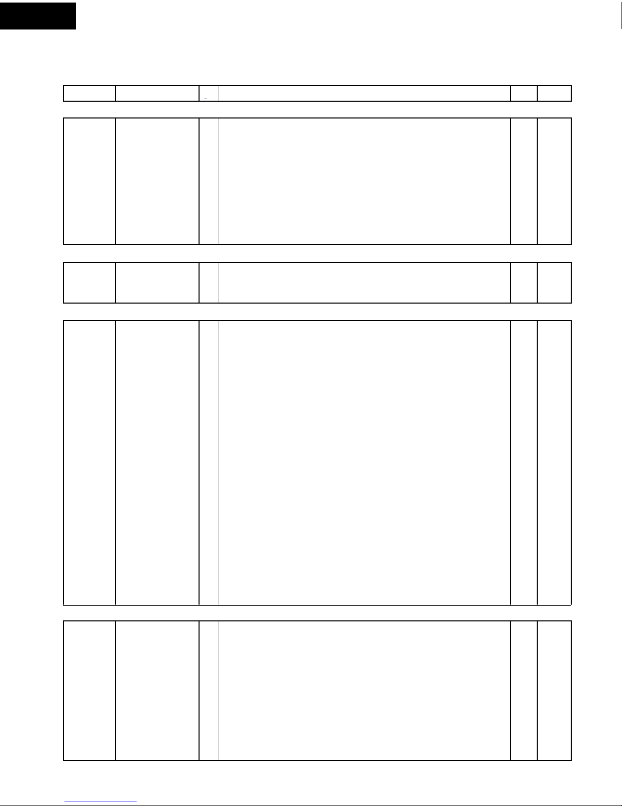
PARTS LIST
Note: The parts marked "∆∆
∆∆
∆" may cause undue microwave exposure.
The parts marked "*" are used in voltage more than 250V. "§" MARK: PARTS DELIVERY SECTION.
∆
ELECTRICPARTS
1- 1 RC-QZA234WRE0 M High voltage capacitor 1 AP
1- 2 FH-DZB013MRY0 M High voltage rectifier assembly 1 AK
1- 3 QSOCLB006MRE0 M Oven lamp socket 1 AE
1-4RLMPTA081WRZZ MOven lamp 1AD
1- 5 RMOTEA346WRE0 M Fan motor 1 AR
1- 6 FFS-BA019/KIT M
Monitor switch (V-16G-2C25), C/T fuse (20A 250V AC) & Inst.
1AF
1- 7 QSW-MA085WRE0 M
Primary interlock switch and door sensing switch (V-5230Q)
2AE
1- 8 QFS-TA050WRZZ M C/T fuse 150OC 1AE
1- 9 QFS-TA014WRE0 M Cavity temperature fuse 150OC 1AF
1-10 RV-MZA305WRZZ M Magnetron 1 BB
1-11 RMOTDA211WRE0 M Turntable motor 1 AL
1-12 RTRN-B077MRE0 M Power transformer 1 AZ
1-13 FACCDB003MRE0 M Power supply cord 1 AM
CABINETPARTS
2-1GDAI-B068MRP0 MBase plate 1AN
2- 2 GLEGPB004MRF0 M Foot 4 AB
2- 3 GCABUB097MRP0 M Outer case cabinet [R-401FK] 1 AU
2- 3 GCABUB088MRP0 M Outer case cabinet [R-401FW] 1 AU
CONTROLPANELPARTS
3- 1 CPWBFB063MRU0 M Control unit 1 BA
3- 1A QCNCMA275DRE0 J 2-pin connector (CN-B) 1 AB
3- 1B FW-VZB194MRE0 M Lead wire harness (WH-1) 1 AG
C1 RC-KZA087DRE0 J Capacitor 0.1 uF 50V 1 AA
C2 VCEA0A1EW108M M Capacitor 1000 uF 25V 1 AB
C3 VCEA0A1AW227M M Capacitor 220 uF 10V 1 -
C21 VCEAB31VW106M J Capacitor 10 uF 35V 1 AA
D1-4 RH-DZA006PRE0 J Diode (1N4002) 4 AD
D20-22 VHD1SS270A/-1 J Diode (1SS270A) 3 AA
D40 VHD1SS270A/-1 J Diode (1SS270A) 1 AA
LD1-4 RH-PXA002DRZZ M Light emitting diode 4 -
Q21 VSKRC243M//-3 J Transistor (KRC243M) 1 AB
R1 VRD-B12HF561J J Resistor 560 ohm 1/2W 1 AA
RY1-2 RRLY-A114DRE0 J Relay (DU12D1-1PR(M)) 2 AN
SP1 RALM-A019DRZZ M Buzzer 1 -
T1 RTRNPA110DRE0 J Transformer 1 AP
VRS1 RH-VZA032DRE0 J Varistor (10G471K) 1 AE
ZD1 VHEHZ4C3///-1 J Zener diode (HZ4C3) 1 AA
3- 2 FPNLCB386/KIT M Control panel sub assembly [R-401FK] 1 AY
3- 2 FPNLCB387/KIT M Control panel sub assembly [R-401FW] 1 AY
3- 2-1 FUNTKB334/KIT M Key unit [R-401FK] 1 AN
3- 2-1 FUNTKB335/KIT M Key unit [R-401FW] 1 AN
3- 2-2 JBTN-B118MRF0 M Open button [R-401FK] 1 AD
3- 2-2 JBTN-B119MRF0 M Open button [R-401FW] 1 AE
3- 2-3 MSPRTA050WRE0 M Open button spring 1 AA
3- 3 PSHEPA798WREZ M LCD sheet 1 AG
3- 4 QCNC-B001MRE0 M Rubber connector 1 AD
3- 5 RLCDSA107DRZZ M Light crystal display 1 -
3- 6 XEPSD30P10XS0 M Screw; 3mm x 10mm 3 AB
OVENPARTS
4- 1 LBNDKB007MRP0 M H.V. Capacitor band 1 AB
4- 2 LANGTB060MRP0 M Chassis support 1 AD
4- 3 PHOK-B018MRF0 M Latch hook 1 AF
4- 4 MLEVPB016MRF0 M Switch lever 1 AD
4- 5 PDUC-B120MRF0A M Magnetron duct 1 AG
4- 6 NFANPB001MRE0 M Fan blade 1 AC
4- 7 PDUC-B088MRF0 M Fan duct 1 AC
4- 8 ------------- M Oven cavity (Not a replaceable part) 1 --
4- 9 PCOVPB073MRP0 M Waveguide cover 1 AC
4-10 PPACGB014MRF0 M Turntable motor packing 1 AA
4-11 PCUSGB033MRP0 M Cushion 1 AA


 User manual")