manuals.online logo
Brands
  1. Home
  2. •
  3. Brands
  4. •
  5. Sharp
  6. •
  7. Microwave Oven
  8. •
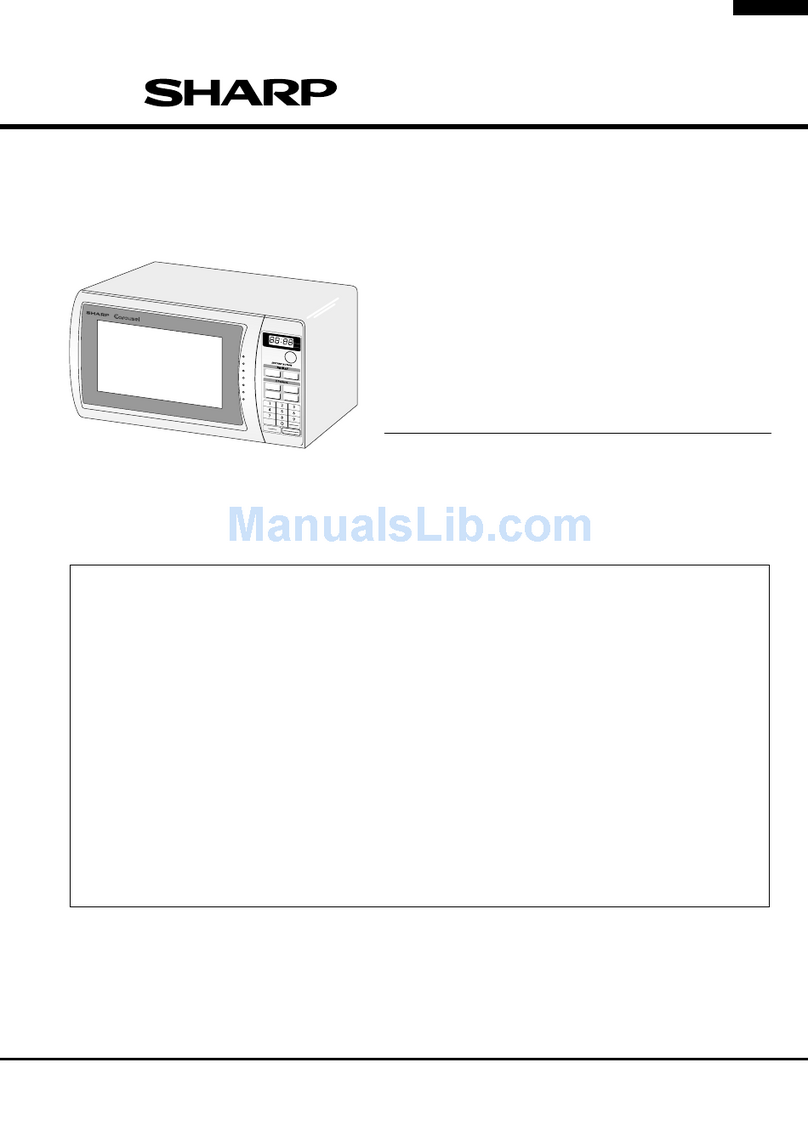
  9. Sharp R-5800A User manual

Sharp R-5800A User manual

Other Sharp Microwave Oven manuals

Sharp R98STM-AA Instruction Manual

Sharp

Sharp R98STM-AA Instruction Manual

Sharp R-330E User manual

Sharp

Sharp R-330E User manual

Sharp Carousel R-309Y User manual

Sharp

Sharp Carousel R-309Y User manual

Sharp R-480C User manual

Sharp

Sharp R-480C User manual

Sharp Carousel R-995J User manual

Sharp

Sharp Carousel R-995J User manual

Sharp SMC1162HS User manual

Sharp

Sharp SMC1162HS User manual

Sharp R-343M Instruction Manual

Sharp

Sharp R-343M Instruction Manual

Sharp R-96STM User manual

Sharp

Sharp R-96STM User manual

Sharp R224HW Use and care manual

Sharp

Sharp R224HW Use and care manual

Sharp Carousel R-210D User manual

Sharp

Sharp Carousel R-210D User manual

Sharp R-350D User manual

Sharp

Sharp R-350D User manual

Sharp Carousel R-350F User manual

Sharp

Sharp Carousel R-350F User manual

Sharp SMC0760HW User manual

Sharp

Sharp SMC0760HW User manual

Sharp SMD2470AS User manual

Sharp

Sharp SMD2470AS User manual

Sharp Carousel SMO1754JS User manual

Sharp

Sharp Carousel SMO1754JS User manual

Sharp SMC1585BSA User manual

Sharp

Sharp SMC1585BSA User manual

Sharp Carousel R-326FS User manual

Sharp

Sharp Carousel R-326FS User manual

Sharp R-508DK User manual

Sharp

Sharp R-508DK User manual

Sharp Twin Touch R-CD2200M User manual

Sharp

Sharp Twin Touch R-CD2200M User manual

Sharp R-630DKA User manual

Sharp

Sharp R-630DKA User manual

Sharp R-3A55 User manual

Sharp

Sharp R-3A55 User manual

Sharp R-15AT User manual

Sharp

Sharp R-15AT User manual

Sharp R-969IN User manual

Sharp

Sharp R-969IN User manual

Sharp R-634 User manual

Sharp

Sharp R-634 User manual

Popular Microwave Oven manuals by other brands

PROFILO MD1000 instruction manual

PROFILO

PROFILO MD1000 instruction manual

Candy MIC 201 EX User instructions

Candy

Candy MIC 201 EX User instructions

PITSOS GMW3101B user manual

PITSOS

PITSOS GMW3101B user manual

Sears 5648744780 Use & care manual

Sears

Sears 5648744780 Use & care manual

BOMANN CB 1272 Instruction manual & guarantee

BOMANN

BOMANN CB 1272 Instruction manual & guarantee

Conrad Electronic 2372935 operating instructions

Conrad Electronic

Conrad Electronic 2372935 operating instructions

GE Spacemaker JVM1440BH datasheet

GE

GE Spacemaker JVM1440BH datasheet

DAEWOO ELECTRONICS KOR-6L8K5S83 Operating instructions & cook book

DAEWOO ELECTRONICS

DAEWOO ELECTRONICS KOR-6L8K5S83 Operating instructions & cook book

DAEWOO ELECTRONICS KOR-1N5A9S Operating instructions & cook book

DAEWOO ELECTRONICS

DAEWOO ELECTRONICS KOR-1N5A9S Operating instructions & cook book

Daewoo KQG-6617G Operating instructions & cook book

Daewoo

Daewoo KQG-6617G Operating instructions & cook book

Samsung M1779 Owner's instructions

Samsung

Samsung M1779 Owner's instructions

GE JES1143 Use and care & cooking guide

GE

GE JES1143 Use and care & cooking guide

Miele H6200BM(TB) Operating and installation instructions

Miele

Miele H6200BM(TB) Operating and installation instructions

Jocel JMO011480 instruction manual

Jocel

Jocel JMO011480 instruction manual

Electrolux EVL8E00X user manual

Electrolux

Electrolux EVL8E00X user manual

STOVES Q900GRF DO User, installation & servicing instructions

STOVES

STOVES Q900GRF DO User, installation & servicing instructions

Daewoo KOR-6L0B3S Operating instructions & cook book

Daewoo

Daewoo KOR-6L0B3S Operating instructions & cook book

KitchenAid KCMS1555 Use and care guide

KitchenAid

KitchenAid KCMS1555 Use and care guide

manuals.online logo
manuals.online logoBrands
  • About & Mission
  • Contact us
  • Privacy Policy
  • Terms and Conditions

Copyright 2025 Manuals.Online. All Rights Reserved.

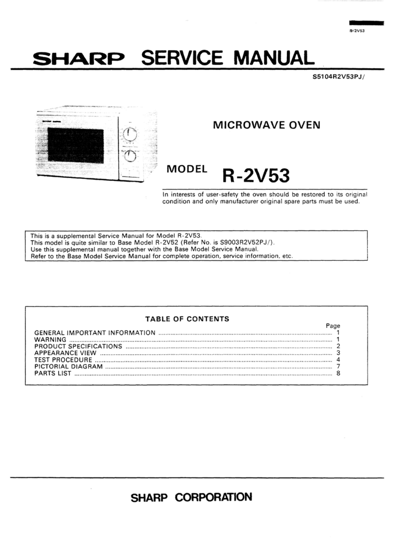
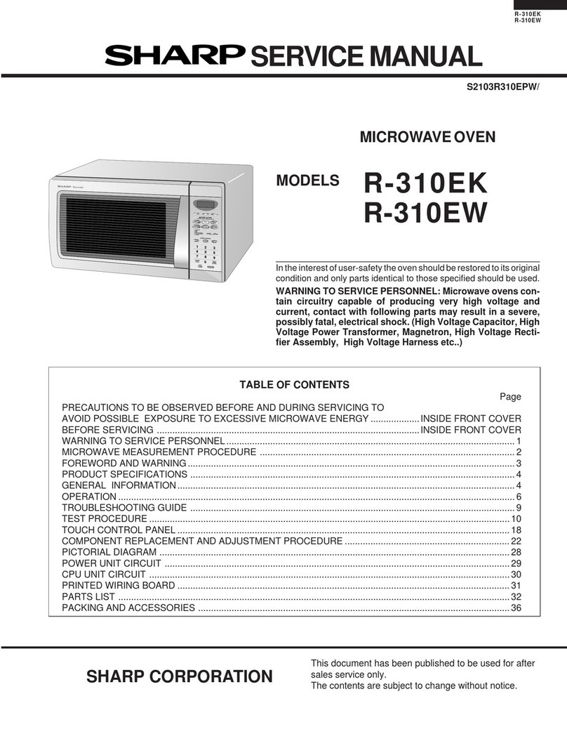
R-5800A
SHARP SERVICE MANUAL
s5401 R580oJ//
MICROWAVE OVEN
MODEL R-5800A
In the interests of user-safety the set should be restored to its original
condition and only parts identical to those specified be used.
r This is supplement Service Manual for R-580OA.
The R-5800A is quite similar to R-5800.
Use this supplement manual together with the Service Manual for R-5800.
Refer to the R-5800 Service Manual for complete operation, service information etc.
/ TABLE OF CONTENTS .
FOREWORD Page
......................................................................... 1
CAUTION, MICROWAVE RADIATION. ...................................................... 1
THUMBINDEX ....................................................................... 1
PRODUCT DESCRIPTION ............................................................... 2
LATCH SWITCH AND MONITOR SWITCH ADJUSTMENT ......................................... 3
MICROWAVEMEASUREMENT ............................................................ 3
SCHEMATICDIAGRAM ................................................................. 4
PICTORIALDIAGRAM ......................................................
PACKING AND ACCESSORIES ................................................. : :
........
: :
..5.6
. .. 7
PARTSLlST......................................................................8~1 6
FIXING PROCEDURE Of- CORD ANCHORAGE ................................................. 17
SHARP CORPORATION
R-5800A
SERVICE MANUAL
SHARP
MICROWAVE OVEN
FOREWORD
This Manual has been prepared to provide Sharp Service
Personnel with complete Operation and Service Information
for the Sharp Microwave Oven, R-5800A. The R-5800A is
quite similar to R-5800.
It is recommended that service personnel carefully study the
entire text of two Manuals (R-5800 and R-5800A1, so they
will be qualified to render satisfactory customer service.
.
CAUTION
MICROWAVE RADIATION
Personnel should not be exposed to the microwave energy
which may radiate from the magnetron or other microwave
generating devices if it is improperly used or connected.
All input and output microwave connections, waveguides,
flanges and gaskets must be secured.
Never operate the device without a microwave energy absorb-
ing load attached.
Never look into an open waveguide or antenna while the
device is energized.
SHARP CORPORATION
OSAKA, JAPAN
R-5800A
PRODUCT DESCRIPTION
EXPLANATION OF MICROWAVE COOKING
The Sharp Counter Top Microwave Oven uses microwave Materials with a high moisture content, like most foods,
energy to produce heat in the food to be cooked. Unlike will absorb microwave energy. As the microwave energy at
conventional ovens microwave energy will cook foods a frequency of 2450 Megahertz enters the food, the
without applying external heat. molecules align themselves with the energy. Because the
microwaves are changing polarity every half cycle, the food
Microwaves, which are short electromagnetic waves of RF molecules are changing direction every half cycle or oscil-
(radio frequency) energy, pass through materials such as lating back and forth 4,900,000,000 times per second. This
glass, paper, china and most plastics. Materials such as high speed oscillation causes friction between the mole-
metal and aluminum foil tend to reflect microwaves and cules, thereby converting the microwave energy to heat.
may be used only as recommended in the cooking instruc-
tions.
SPECIFICATIONS
Power requirements 240V
50Hz
Single phase, 3 wire earthed
Power consumption 950w
Microwave output power
Case dimensions
Width
Height
Depth
Cooking cavity dimensions
Width
Height
Depth
Turntable diameter
500W (2 litre water load)
.
500mm
335mm
369mm 1
/
1
I
I 295mm
j 187mm
307mm /
280mm
I Control complement Cook Switch
30 min. Single Speed Timer
Variable Cooking Control
Repetition Rate:
HIGH:
Weight I
i
Full power throughout the cooking time.
MED. HIGH:
23.2 sec. ON, 6.8 sec. OFF, approx. 70% of full power.
MED.:
16.5 sec. ON, 13.5 sec. OFF, approx. 50% of full power.
MED. LOW: (DEFROST)
9.8 sec. ON, 20.2 sec. OFF, approx. 30% of full power.
LOW:
5 sec. ON, 25 sec. OFF, approx. 10% of full power.
Approx. 16kg.
R-5800A
LATCH SWITCH AND MONITOR SWITCH ADJUSTMENT
In case the latch switch and monitor switch do not operate
properly due to a misadjustment, the following adjustment
should be made.
1. Loosen the single (1) screw holding the latch hook to the
plate of open device.
2. With the door closed, adjust the latch hook by moving it
back and forward or up and down.
3.
4.
In and out play of the door allowed by the latch hook
should be less than 0.5mm. The vertical position of the
latch hook should be placed where the latch switch and
monitor switch have activated with the door closed.
Secure the screw with washer firmly.
Now, make sure of the latch switch operation. If the latch
switch has not activated with the door closed, loosen the
single (1) screw holding the latch hook to the plate of the
open device and adjust the latch hook position.
,S.,
’ ‘11, \
: LEVER
After the adjustment, make sure of the following points:
1. The In and out play of the door remains less than 0.5 mm
Figure 1. Latch switch and Monitor
Switch Adjustment
at latched position.
First check the latch hook position, pushing and pulling
the lower portion of door toward the oven face. The result
(play of the door) should be less than 0.5 mm.
2. The latch switch interrupt the circuit before the door can
be opened.
3. The monitor switch contacts close when the door is opened.
4. Re-install the outer case and check for microwave leakage
around the door with an approved microwave survey meter.
. MICROWAVE MEASUREMENT
After the adjustment of the door interlock switches and door Recommended instruments are:
is completed individually or collectively, the following leakage NARDA 8100
test must be performed with a survey instrument and it must NARDA 8200
be confirmed that the result meets the requirements of the HOLADAY HI 1500
performance standard for microwave oven. SIMPSON 380M
REQUIREMENT
The safety switch must prevent microwave radiation emission
in excess of 5mW/cm2 at any point 5cm or more from ex-
ternal surface of the oven.
PREPARATION FOR THE TESTING:
Before beginning the actual test for leakage, proceed as
follows;
1. Make sure that the test instrument is operating normally as
specified in its instruction booklet.
Important:
Survey instruments that comply with the requirement for
instrumentation as prescribed by the performance standard
for microwave ovens must be used for testing.
2. Place the turntable tray into the oven cavity.
3. Place the load of 275 +15ml of water initially at 20*5’C in
the centre of the oven tray. The water container should be
a low form of 600ml beaker with inside diameter of
approx. 8.5cm and inade of an electrically non-conductive
material such as glass or plastic.
The placing of this standard load in the oven is important
not only to protect the oven, but also to insure that any
leakage is measured accurately.
4. Close the door and turn the oven ON with the timer set for
several minutes. If the water begins to boil before the
survey is completed, replace it with 275ml of the cool
water.
5. Move the probe slowly (not faster than 2.5cm/sec.) along
the gap.
6. The microwave radiation emission should be measured at
any point of 5cm or more from the external surface of the
oven.
3
R-5800A
CIRCUIT SUBJECT TO CHANGE
WITHOUT NOTICE 240V ‘v 50Hz
WIRE COLOUR CODE & SYMBOL
RED: RED WHT : WHITE
BRN: BROWN BLU : BLUE
ORG: ORANGE GRY : GRAY
GRN: GREEN
G-Y GREEN AND YELLOW STRIPE 0.75mm’
HV : HIGH VOLTAGE WIRE
/18 : SECTIONAL AREA OF 0.75mm’ MIN
: NO INdlCATlON SHOWS 0.3mm2 MIN
0 : QUICK CONNECT TERMINAL
0 : SOLDER OR CLINCH TERMINAL
0 : CONNECTOR
- F: FUSE
250V M6.3A
WHT/18 sw3:
MONITOR
. BLK/18 SWITCH BRN
T
TF: MAGNETRON
TEMP. FUSE
WHT
I Ml : FAN MOTOR
WHT L
Ll, L2: OVEN LAMP RED
. I
I ORG/lB
I M2: TURNTABLE MOTOR I
I I
/
, BLK/lS ORG / 1
BLK I
I TS: TIMER /
BLK
I I A
------_
wJJ)JJJ+ RED’18 Y
“T+ m i ~WERTRANSFORMER
CAPACITOR
----
d ---v-
MG: MAGNETRON
D: RECTIFIER
18
Figure 2. Schematic Diagram
4
R-5800A R-5
1 2 11 3 I 4 5 6 7
f
1
t
Ir
--4ORG t
MA
TEh
r--- _---e-N
I I 1
CORD
MOUNTING
BRACKET
CONTROL PANEL ASS’Y a CORD
Figure 3. Pictori
i 1 2 3 4 5 6 I 7
5
-5800A R-5800A
7 8 9 I 10 I 11 1 12
1
P
OVEN LAMP
TURNTABLE
MOTOR
CONNECTOR
ORG
IWHT
c
c
MAGNETRON
TEMP. FUSE
I I’ -“1
MAGNETROil I jl
I
i ( -
-
- >
-4 FAN MOTOR
1
!
+
pVHTj--
I
RECTIFIER
1 RED HIGH
VOLTAGE
CAPACITOR
we 3. Pictorial Diagram
! 7 I 8 I 9 I 10 1
/ 11 I 12
6
R-5800A
PACKING AND ACCESSORIES
TRAY HOLDER
(SPADFO417WREO)
PACKING ADD KIT
(CPADBOI B5WR KO)
POLYETHYLENE BAG
’ (SSAKHOO96WREO)
OUTER CASE
PROTECTION BOARD
’ (SPADP0280WREO)
,MICROWAVE OVEN
OPERATION AND i’
COOK BOOKLET /
7
4 R-5800A
PARTS LIST
.:
- __
IREF.NO. 1 PART NO. DESCRIPTION Q’TY CODE 1
-
ELECTRICAL PARTS
l- 1 / QACCAO 0 2 4WR E 0 / Mains supply cord 1 AR
’l- 2 IQFS-C0019WREO FuseM6.3A 1 AE
’
l- 3 / QFSHDOO 19WREO Fuse holder 1 AF
l- 4 / QSW-MO 16 1WRE 0 Cook (latch) switch 1 AG
l- 5 / QSW-MO 16 2WR E 0 Monitor switch 1 AG
l- 6 ) QSW-MO 16 3WR E 0 Latch switch 1 AG
l- 7 /RLMPT~~~~wREO Ovenlamp 2 AF
l-8 / QSoCL0055WREO Oven lampsocket 2 AG
l- 9 :RMoTE0172WREO, Fanmotor 1 AX
l-10 / RMOTDO 0 7 OWR E 0 1 Turntable motor 1 AU
/
l-11 iQSWTE0191WREO Timer 1 AW
1-12 Q SWT E 0 19 2 WR E 0 Vari-motor assembly 1 AY
,
1-13 I QF S-T 0 0 2 3 WR E 0 Magnetron temp. fuse 1 AH
1-14 j FV-MZO 14 lWRK0 Magnetron 1 BM
1-15 RC-Q Z 0 10 7WR E 0 High voltage capacitor 1 AX
1-16 / RH-DZ 0 0 6 8WR E 0 ; Rectifier 1 AQ
’1-17 / R T RN-O 2 6 8WR E 0 i Power transformer 1 BP
CABINET PARTS
I
2- 1 ; GCABUO 14 6WRP 0 Outer case cabinet 1 AX,
2- 2 FANGRO 0 6 6WRY 0 ; Unit chassis 1 AM
2- 3 LANGF 0 3 12WRWO ’ Oven supporting plate 1 AE
2- 4 FHNG-0 0 8 GWRMO I Lower oven hinge 1 AM
2- 5 PSPAG0019WRPO Rubberspacer 1 AB
2- 6 GLEGP0007YBEO / Foot I 4 I AB
I
2- 7 FLEVFO 123WRKO Open device / 1 j AP
I I
2- 8 LANGK 0 14 1WRF 0 Latch hook I 1 1 AF
I
2- 9 ML EV F 0 1 2 4WR E 0 Monitor switch lever 1 AC
2-10 LANGQO 4 0 OWRWO Cord mounting bracket / 1 AD
I
2-11 LSTPP0009YBFO Cordanchorage(lower) / 1 / AC
2-12 LSTPPO 0 0 8YBF0 Cord anchorage (upper) II 1 AC
/
2-13 LBSHC0032WREO / 1 AB
2-14 LANGKO 2 4 3WRW0 !
Cord bushing :
I
Capacitor holder I 1 i AC
I
2-15 PCOVWO 0 2 5WR P 0 High voltage cover 1 1 AB
2-16 PSPAGQ 0 0 2 Y B E 0 Vibration proof cushion 1 AA
I
2-17 PZETNOO 18WRE0 , Terminal cover 1 AA
/
2-18 / TMAPC0598WRRO Schematicdiagram 1 AB
I
!
Note : The parts marked “%” are used in voltage more than 250V.
8
R-58OOA
IREF.NO. j PART NO. DESCRIPTION ’ Q’TY j CODE 1
CONTROL PANELPARTS
3- 1 1HPNLC0248WRRO Control panel frame I 1 AQ
3- 2 i HDECQ016 2WRF0 Decoration sash (right) I 1 AG
3- 3 / FKNBK0165WRKO Timerknob / 1 AE
3-4 FKNBKO 16 7WRK0 Variable cooking control knob 1 AE
, , /
I
3- 5 JBTN-0159WRFO Cook button and open button 2 AC
3- 6 MSPRC0062WREO Buttonspring 2 AB
OVEN PARTS
4- 1 DOVN-0219WRKO Oven cavity
4- 2 1 FTNT-003 lWRH0 Turntable tray
4- 3 'PCoVPO3 22WRE0 Magnetron cover
4- 4 PCLICOO~~WREO Clip
4- 5 PF i LW0044WRPO Oven lamp filter
4- 6 I HDECAO 7 2 OWRPO Dectration sash (upper)
4- 7 I HDECA0721WRPO Decoration sash(lower)
4- a ~HDECQO 16 1WR F 0 Decoration sash (left)
4-9 ; FHNG-0085WRMO Upper oven hinge
4-10 PDUC-0431WRWO Air duct
I 1 BL
1 AV
1 AH
4 AA
1 AB
1 AH
1 AH
1 AG
1 AE
'
1 AG
4-11
4-1lA
4-12
4-13
4-14
4-15
4-16
4-17
4-18
4-19
4-20
4-21
4-22
4-23
4-24
FFANJ0025WRKO
t
I 1
I
I
I
VlSPRP0038YBEO
LANGF0316WRWO
PCaVP0306WRPO
FANGT0060WRWO
NBALS0020WREO
NSFTT0073WRFO
NGERH0097WRFO
NBRGM0026WRMO
LANGQ0372WRWO
PSKR-0072WRWO
PCUSG0301WREO
PCUSG0302WREO
PCUSG0303WREO
PCUSG0306WRPO
Fan blade assembly
Fan retainer clip
Motor supporting plate
Turntable motor cover
Gear case
Ball
Driving shaft
Driving gear
Gear case cover
Lamp socket mounting plate
Air guide
Motor cushion
Water proof cushion A
Water proof cushion B
Water proof cushion C
DOOR PARTS
1 AF
1 AB
1 1 AF
1 / AD
1 1 AG
1 I AA
1 / AF
1 ’ AC
1 AF
-+-%
1 1 AC
1 j AB
1 ! AA
1 AB
5 1DDORF0413WRKO Door assembly, complete / 1 BG
5- 1 HPNL-0017WRRO Doorscreen I 1 AV
5- 2 : FDoRF0165WRWO Door panel I 1 AR I
9