6
R-630DKA
R-630DSA
R-630DWA
3. Door is positioned with its face pressed toward cavity
face plate.
4. Check for microwave leakage around door with an
approvedmicrowavesurveymeter. (RefertoMicrowave
Measurement Procedure.)
Note:
The door on a microwave oven is designed to act as
an electronic seal preventing the leakage of
microwaveenergyfromovencavityduringcookcycle.
This function does not require that door be air-tight,
moisture(condensation)-tightorlight-tight.Therefore,
occasional appearance of moisture, light or sensing
ofgentlewarmair movement aroundovendoorisnot
abnormalanddonotofthemselvesindicatealeakage
of microwave energy from oven cavity.
Figure C-7. Door Replacement
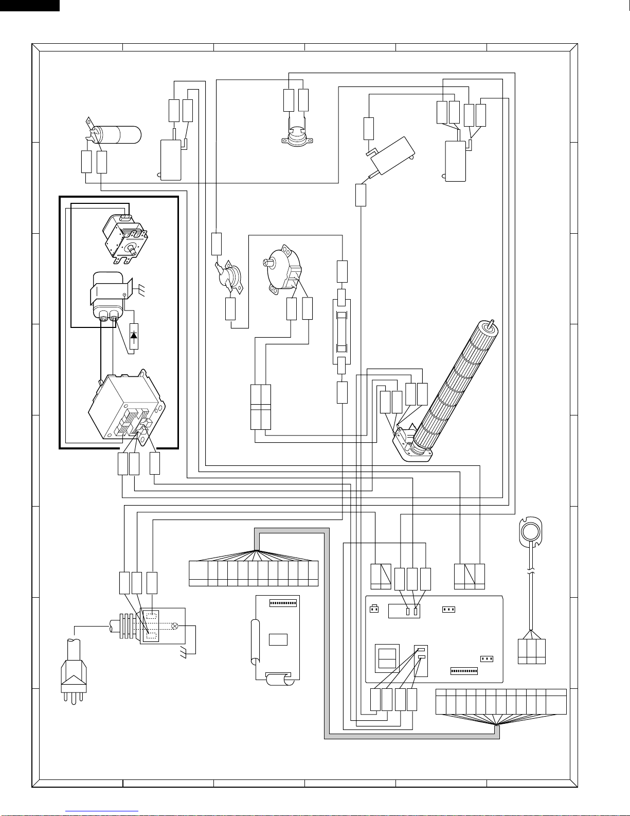
Figure C-8. Routing of 12-pin wire harness
SEALER FILM
Installation
1. Put the adhesive tape on the backing film of the sealer
film as shown in Fig. C-9.
2. Tear the backing film by pulling the adhesive tape.
3. Put the pasted side of the sealer film on the door panel.
Figure C-9. Sealer film
REMOVAL
1. Disconnect the power supply cord and then remove the
outer case.
2. Open the door slightly.
3. Todischargehighvoltagecapacitor,waitfor 60seconds.
4. Disconnect the 12-pin wire harness from the power unit
on the base plate.
5. Insert a putty knife (thickness of about 0.5mm) into the
gap between the choke cover and door frame as shown
in Figure C-6 to free engaging parts.
6. Pry the choke cover by inserting a putty knife as shown
Figure C-6.
7. Release choke cover from door panel.
8. Now choke cover is free.
NOTE: Whencarryingout anyrepairtothe door, donot
bend or warp the slit choke (tabs on the door
panelassembly)to prevent microwaveleakage.
Figure C-6. Door Disassembly
9. Release two (2) pins of door panel from two (2) holes of
upper and lower oven hinges by lifting up.
10.With pulling out the 12-pin wire harness from the hole of
the oven cavity front plate and the front leg, remove the
door from the oven cavity.
11.Now, the door is free from the oven cavity.
REINSTALLATION
1. Insertthe12-pinwireharnesstotheholesofthefrontleg
and the oven cavity front plate.
2. Catchtwo(2) pinsofdoorpanelon two(2)holeof upper
and lower oven hinges.
3. Re-install choke cover to door panel by pushing.
4. Connectthe12-pinwireharnesstothepowerunitonthe
base plate.
5. Now the door is installed.
Note: After any service to the door;
(A) Makesurethatdoorsensingswitchandsecondary
interlock switch are operating properly. (Refer to
chapter “Test Procedures”.).
(B) An approved microwave survey meter should be
usedto assure compliance with propermicrowave
radiation emission limitation standards.
After any service, make sure of the following :
1. Door latch heads smoothly catch latch hook through
latch holes and that latch head goes through center of
latch hole.
2. Deviationofdooralignmentfromhorizontallineofcavity
face plate is to be less than 1.0mm.
DOOR REPLACEMENT
Putty knife
Door frame
Choke cover
COMPONENT REPLACEMENT AND ADJUSTMENT PROCEDURE
Upper oven hinge
Upper
oven
hinge
Slit choke of
door panel
Lower oven
hinge
Lower
oven
hinge
Choke cover
Pin
Pin
Tab
Hole
Door Screen
Hole
Front leg
Oven cavity front plate
12-pin wire harness
12-pin wire
harness
Power unit
Base plate
Door
Front leg
Sealer film Backing film
Adhesive tape