R-9370
OPERATING INSTRUCTIONS
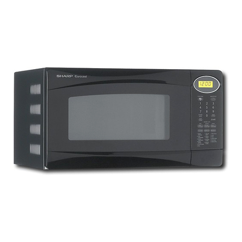
OPERATION OF AUTO-TOUCH” CONTROL
PANEL
Your new Auto-Touch microwave oven uses a microprocessor, the electronic brain that provides the
wide variety of cooking programmes which could not be achieved by conventional control methods. The
operation of the oven is controlled by touching the appropriate pads arranged on the surface of the con-
trol panel. The lighted digital readout will display the cooking time, Sensor Cook, or Compu Defrost set- I
ting or time:of day or minute timer. Indicators show the variable cooking setting and cooking function
you have programmed.
An entry signal tone should be heard each time you touch the control panel to make a correct entry.
If you do not hear this sound,
1) You have not used enough pressure in touching the pad.
2) You have made more entries than the control panel will accept.
3) You have made an incorrect entry. I
In addition to the entry signal tone, an audible signal will sound for approximately 2 seconds at the end
of the cooking cycle.
* Make sure the oven is plugged into a power point. When the oven is plugged in, the display show
[88:581, flashing on and off each second. Touch the STOP/CLEAR pad: [“-?F] will appear.
* You cannot programme the oven if the door is not closed firmly.
* During cooking, the programme cannot be changed until the STOP/CLEAR pad is touched twice.
All functions are locked in to prevent accidental changes.
If food does not seem to be heating properly, check the indicator immediately below the lighted digital
display. Be sure the Variable Cooking Control is on the proper setting.
* If the electrical power supply to your microwave oven should be interrupted, the display will intermit-
tently show 185:88] after the power is reinstated. If this occurs during cooking, the programme will
be erased. The time of day will be also erased. Simply reset the clock for the correct time of day.
Auto-TouchTMControl Panel
I 7 INDICATORS
LIGHTED DIGITAL DISPLAY
CMP”MfOLowMI0“IL” Shows readout of cooking time, cooking instruction or time of day.
7
3
3
9 r
NUMBER PADS
Touch to enter cooking times, clock time or weight of food.
REHEAT SENSOR PAb
Touch to reheat food.
COMPU DEFROST PAD
Touch to select Compu Defrost settings.
VARIABLE COOKING CONTROL PADS
Touch to select microwave power-setting. If not touched, HIGH
is automatically selected.
STOP/CLEAR PAD
Touch to erase during programming.
Touch once to stop operation of oven during cooking; touch twice
to cancel cooking program.
AUTO START/CLOCK PAD
Touch to set clock or auto start time.
START PAD
Touch to start oven.
INSTANT COOK PAD
Touch to cook for 1 minute at HIGH or increase by 1 minute mul-
tiples during variable cooking.
TIMER/HOLD PAD
Touch to set minute timer or HOLD function.
3
