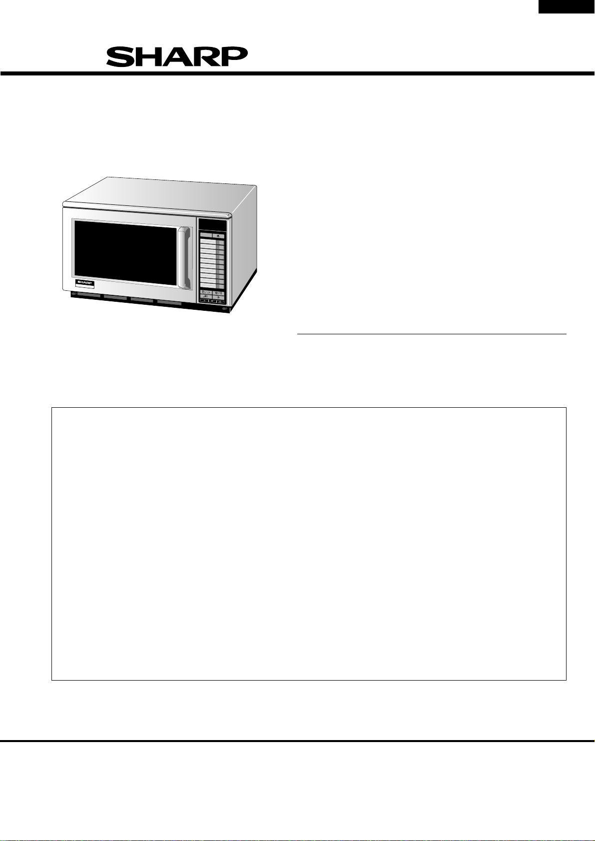
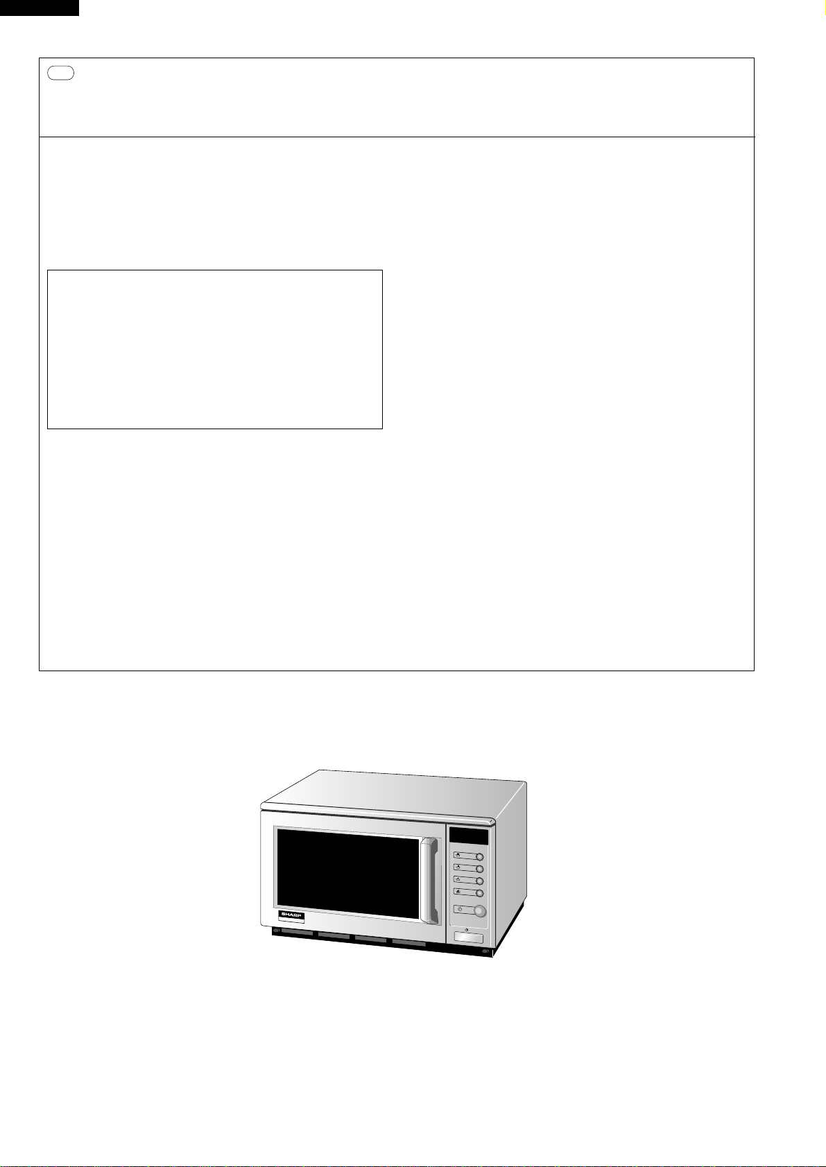
Sharp R-22AM User manual

R-22AM
R-23AM
R-23AT
SHARP CORPORATION
SERVICE MANUAL
SY911R23ATH/
COMMERCIAL
MICROWAVE OVEN
MODELS R-22AM
R-23AM
R-23AT
In interests of user-safety the oven should be restored to its
original condition and only parts identical to those specified
should be used.
TABLE OF CONTENTS Page
CAUTION, MICROWAVE RADIATION....................................................................... INSIDE FRONT COVER
WARNING..........................................................................................................................................................1
SERVICING ...................................................................................................................................................... 2
PRODUCT SPECIFICATIONS ......................................................................................................................... 5
GENERAL INFORMATION................................................................................................................................5
APPEARANCE VIEW ....................................................................................................................................... 6
OPERATION SEQUENCE................................................................................................................................ 7
FUNCTION OF IMPORTANT COMPONENTS ................................................................................................ 9
TROUBLESHOOTING GUIDE ........................................................................................................................10
TEST PROCEDURE ........................................................................................................................................12
TOUCH CONTROL PANEL ASSEMBLY ........................................................................................................20
COMPONENT REPLACEMENT AND ADJUSTMENT PROCEDURE ........................................................... 31
MICROWAVE MEASUREMENT .................................................................................................................... 38
TEST DATA AT A GLANCE ........................................................................................................................... 39
WIRING DIAGRAM ......................................................................................................................................... 39
PICTORIAL DIAGRAM ................................................................................................................................... 41
CONTROL PANEL CIRCUIT ...........................................................................................................................42
PRINTED WIRING BOARD .............................................................................................................................45
PARTS LIST ................................................................................................................................................... 46
R-23AT
1800W/R-23AT
1
2
3
4
5
6
7
8
9
0
11
12
13
14
15
16
17
18
19
20
x 2

R-22AM
R-23AM
R-23AT
CAUTION
MICROWAVE RADIATION
Personnel should not be exposed to the microwave energy which may radiate from the
magnetron or other microwave generating devices if it is improperly used or connected.
All input and output microwave connections, waveguides, flanges and gaskets must be
secured.
Never operate the device without a microwave energy absorbing load attached.
Never look into an open waveguide or antenna while the device is energized.
VARNING
MICKROVAGSSTRALING
Personal får inte utsättas för mikrovågsenergi som kan ustrala från magnetronen eller
andre mikrovågsalstrande anordningar om dessa är felanslutna eller används på fel sätt.
Alla in-och utgångsanslutningar för mikrovågor, vagledare, flänsar och packningar måste
vara fast anslutna.
Mikrovågsgeneratorn får inte arbeta utan att absorberande belastning är ansluten. Titta
aldrig in i ën öppen vågledare eller antenn när mikrovågsgeneratorn är påkopplad eller
laddad.
VAROITUS
MIKROAALTOSÄTELYÄ
Käyttäjä ei saa joutua alttiiksi mikroaaltoenergialle, jota voi säteillä magnetronista tai
muusta mikroaaltoja kehittävästä laitteesta, jos sitä käytetään tai jos se kytketään väärin.
Kaikkien mikroaaltoliitäntöjen sekä syöttö-että ulostulopuolella, aaltoputkien laippojen ja
tiivisteiden tulee olla varmistettuja.
Mikroaaltouunnia ei koskaan saa käyttää ilman kuormaa jossa mikroaaltoenergiaa kuluu.
Avoimeen aaltoputkeen tai antenniin ei koskaan saa katsoa virran ollessa kytkettynä.
ADVARSEL
MIKROBØLGESTRÅLING
Personell må ikke utsettes for mikrobølge-energi som kan utståles fra magnetronen eller
andre mikrobølge-generende deler dersom apparatet feilbetjenes eller blir feiltikoplet.
Alle inn-og ut-tilkoplinger i forbindelse med mikrobølge-strålingen, bølgeledere, flenser og
tetningsringer/pakninger må festes ordentlig.
Aldri bruk apparatet med mindre en mikrobålge-absorberende last er plassert i
ovnsrommet.
Aldri se direkte inn i en åpen bølgeleder eller antenne imens apparatet er strømførende.
ADVARSEL
MIKROBØLGEBESTRÄLING
Man bør ikke udsætte sig for mikrobølgebestråling fra magnetronen eller andre
mikrobølgefrembringende anordninger, hvilket kan ske hvis apparatet er forkert tilsluttet
eller bruges forkert. Alle mikrobølgeindgange og-udgange, bølgeledere, flanger og
tætningsstrimler må være forsvarligt udført.
Anvend aldrig ovnen uden en mikrobølgesabsorberende anordning. Se aldrig ind i en
åben bølgeleder eller antenne, mens ovnen er i brug.

1
R-22AM
R-23AM
R-23AT
SERVICE MANUAL
COMMERCIAL MICROWAVE OVEN
R-22AM/ R-23AM/ R-23AT
GENERAL IMPORTANT INFORMATION
This Manual has been prepared to provide Sharp Corp. Service
engineers with Operation and Service Information.
It is recommended that service engineers carefully study the entire
text of this manual, so they will be qualified to render satisfactory
customer service.
CAUTION
MICROWAVE RADIATION
DO NOT BECOME EXPOSED TO RADIATION FROM THE
MICROWAVE GENERATOR OR OTHER PARTS THAT CON-
DUCT MICROWAVE ENERGY.
WARNING
Note: The parts marked "*" are used in voltage more
than 250V. (Parts List)
Anm: Delar märket med "*" har en spänning
överstigande 250V.
Huom: Huolto-ohjeeseenmerkitty"tähdella"osatjoissa
jännite on yli 250 V.
Bemerk: Deler som er merket "asterisk" er utsatt for
spenninger over 250V til jord.
Bemærk: "Dele mærket med stjerne benyttes med højere
spænding end 250 volt.
WARNING
Never operate the oven until the following points are ensured.
(A) The door is tightly closed.
(B) The door brackets and hinges are not defective.
(C) The door packing is not damaged.
(D) The door is not deformed or warped.
(E) There is not any other visible damage with the oven.
Servicing and repair work must be carried out only by trained service
engineers.
All the parts marked "*" on parts list are used at voltage more than
250V.
Removal of the outer wrap gives access to potential above 250V.
All the parts marked "∆" on the parts list may cause undue
microwave exposure, by themselves, or when they are damaged,
loosened or removed.
SHARP CORPORATION
OSAKA, JAPAN
SERVICING
PRODUCT SPECIFICATIONS
GENERAL INFORMATION
APPEARANCE VIEW
OPERATING SEQUENCE
FUNCTION OF IMPORTANT
COMPONENTS
TROUBLESHOOTING GUIDE
AND TEST PROCEDURE
TOUCH CONTROL PANEL
COMPONENT REPLACEMENT
AND ADJUSTMENT PROCEDURE
MICROWAVE MEASUREMENT
TEST DATA AT A GLANCE
WIRING DIAGRAM
PARTS LIST

2
R-22AM
R-23AM
R-23AT
REMEMBER TO CHECK 3D
1) Disconnect the supply.
2) Door opened, and wedged open.
3) Discharge two high voltage capacitors.
WARNING: AGAINST THE CHARGE OF THE TWO
HIGH-VOLTAGE CAPACITORS
The two high-voltage capacitors remains charged about 60
seconds after the oven has been switched off. Wait for 60
seconds and then short-circuit the connection of the two
high-voltagecapacitors(thatis,oftheconnectingleadofthe
high-voltage rectifier) against the chassis with the use of an
insulated screwdriver.
Sharp recommend that wherever possible fault-finding is
carried out with the supply disconnected. It may in, some
cases, be necessary to connect the supply after the outer
casehasbeenremoved,inthiseventcarryout3Dchecksand
then disconnect the leads to the primary of the two High
voltagetransformers.Ensurethattheseleadsremainisolated
fromothercomponentsandtheovenchassis.(Useinsulation
tapeifnecessary.)Whenthetestingiscompletedcarryout3D
checksandreconnecttheleadstotheprimaryofthetwoHigh
voltage transformers.
SERVICING
WARNING TO SERVICE PERSONNEL
GB Microwaveovenscontaincircuitrycapableof producing veryhighvoltageand current, contactwithfollowingpartswill result
inelectrocution. Highvoltagecapacitor,Highvoltagetransformer,Magnetron,Highvoltagerectifierassembly,Highvoltage
fuses, High voltage harness.
REMEMBER TO CHECK 4R
1) Reconnect all leads removed from components during
testing.
2) Replace the outer case (cabinet).
3) Reconnect the supply.
4) Run the oven. Check all functions.
Microwave ovens should not be run empty. To test for the
presence of microwave energy within a cavity, place a cup of
cold water on the oven turntable, close the door and set the
powertoHIGH andset themicrowave timer forone (1)minute.
When the one minute has elapsed (timer at zero) carefully
check that the water is now hot. If the water remains cold carry
out 3D checks and re-examine the connections to the compo-
nent being tested.
When all service work is completed, and the oven is fully
assembled,themicrowavepoweroutputshouldbecheckedand
a microwave leakage test should be carried out.
NL Magnetronovens bevatten circuits die een zeer hoge spanning en stroom kunnen voortbrengen. Contact met de
volgende onderdelen kan elektrocutie tot gevolg hebben.
Hoogspanningscondensator, hoogspanningstransformator, magnetron, hoogspanningsgelijkrichter, hoogspannings
kabelboom.
VERGEET DE VOLGENDE 3 STAPPEN NIET
1) Haal de stekker uit het stopcontact.
2) Open de deur en zorg ervoor dat hij niet dicht kan vallen.
3) Ontlaad de hoogspanningscondensator.
PAS OP VOOR DE ELECTRISCHE LADING VAN DE
HOOGSPANNINGSCONDENSATOR
De hoogspanningscondensator blijft nog ongeveer 60
seconden lang opgeladen, nadat de oven is uitgeschakeld.
Wacht 60 seconden voordat u de verbinding van de
hoogspannings-condensator (m.a.w. de verbindingsdraad
van de hoogspanningsgelijkrichter) met een geïsoleerde
schroevedraaier kortsluit tegen het chassis.
Sharp beveelt ten sterkste aan dat, voor zover mogelijk,
defecten worden opgespoord wanneer de stekker uit het
stopcontactisgehaald.Somsishetnodigomdestroomtoevoer
weer tot stand te brengen nadat de buitenmantel verwijderd
is. Herhaal dan de bovengenoemde 3 stappen en haal de
electrische draden uit de primaire zijde van de
vermogenstransformator. Zorg ervoor dat deze draden
geïsoleerd blijven van andere elementen en van het chassis
van de oven. (Gebruik zo nodig isolatieband.) Wanneer de
test is uitgevoerd, herhaalt u de bovenstaande 3 stappen en
verbindt u de electrische draden weer aan de primaire zijde
van de vermogenstransformator.
VERGEET DE VOLGENDE 4 STAPPEN NIET
1) Sluit de draden weer aan diezijn losgehaald voor de test.
2) Plaatsdebuitenmantel weeromhettoestelheen(kabinet).
3) Stop de stekker weer in het stopcontact.
4) Zet de oven aan. Controleer alle functies.
Magnetronovens mogen niet leeg aangezet worden. Om te
controleren of er microgolf-energie binnen de oven wordt
geproduceerd, plaatst u een mok met koud water op de
draaitafel van de oven, sluit de deur, zet de oven op HIGH en
steltdeklokvandemagnetroninoptwee(2)minuten.Wanneer
de twee minuten voorbij zijn (klok staat op nul), controleert u
voorzichtig of het water heet is. Indien het water nog steeds
koud is, herhaalt u de allereerste drie stappen en controleer
nogmaals de aansluitingen naar de geteste onderdelen.
Wanneer alle reparaties zijn uitgevoerd en de oven weer in
elkaar is gezet, moet de het magnetronvermogen worden
gecontroleerd en moet worden gecontroleerd of er geen
microgolflekkage is.

3
R-22AM
R-23AM
R-23AT
E Los hornos de microondas contienen circuitos eléctricos capaces de producir voltajes de alta tensión y descargas
eléctricas.Para evitarel riesgo deelectrocución, absténgasede tocarlos siguientescomponentes:condensador dealta
tensión, transformador de alta tensión, magnetrón, dispositivo del rectificador de alta tensión y arnés de alta tensión.
RECUERDE LA COMPROBACION 3D
1) Desconecte la alimentación.
2) Deje la puerta abierta y calzada.
3) Descargue el condensador de alto voltaje.
ADVERTENCIA SOBRE LA CARGA DEL
CONDENSADOR DE ALTO VOLTAJE
El condensador de alto voltaje permanece cargado unos
60 segundos después de haber apagado el horno. Espere
60segundos yluego pongaen cortocircuitola conexión del
condensador de alto voltaje (esto es, del conductor de
conexión del rectificador de alto voltaje) al chasis con un
destornillador de mango aislado.
Se recomienda encarecidamente que siempre que sea
posiblela localizaciónde fallos serealice conlaalimentación
desconectada. Puede ser que en algunos casos sea
necesarioconectar laalimentación despuésdehaber retirado
lacarcasa exterior.En estecaso,realice lascomprobaciones
3D y luego desconecte los conductores del primario del
transformador de alimentación. Asegúrese de que estos
conductores permanezcan aislados de otros componentes y
del chasis del horno. (Use cinta aislante si es necesario).
Cuando termine la prueba efectúe las comprobaciones 3D y
reconecte los conductores al primario del transformador de
alimentación.
RECUERDE LA COMPROBACION 4C
1) Conecte todos los componentes desconectados de los
componentes durante la prueba.
2) Coloque la carcasa exterior (cabina).
3) Conecte la alimentación.
4) Compruebe todas sus funciones despues de poner en
marcha el horno.
Los hornos de microondas no deben funcionar vacíos. Para
comprobar la presencia de energía de microondas dentro de
unacavidad,coloque unatazade aguafría enel platogiratorio
del horno, cierre la puerta y ponga la potencia en HIGH (alta)
y coloque el temporizador en dos (2) minutos. Cuando
transcurran los dos minutos (temporizador a cero) compruebe
cuidadosamente que el agua se ha calentado. Si el agua
permaneciese fría, efectúe las comprobaciones 3D y vuelva a
examinar las conexiones de los componentes que han sido
probados.
Cuandohaya terminado laintervención enel equipo yel horno
haya sido ensamblado de nuevo completamente, deberá
comprobar la potencia de salida de microondas y realizar una
prueba de fugas de microondas.
SV Mikrovågsugnar innehåller kretsar som producerar mycket höga spänningar och strömmar.
Kontakt med följande komponenter kan leda till dödsfall:
Högspänningskondensator, transformator, magnetron, högspännings likriktare, högspännings kablage.
KOM IHÅG ATT KONTROLLERA 3 STEG
1) Koppla från strömkällan.
2) Öppna dörren på glänt.
3) Ladda ur högspänningskondensatorn.
VARNING FÖR LADDNINGEN I
HÖGSPÄNNINGSKONDENSATORN
Högspänningskondensatorn är laddad i 60 sekunder efter
det att ugnen stängts av. Vänta 60 sekunder och korislut
sedan kondensatoms anslutning (dvs anslutningen till
högspänningslikriktaren)tillchassietmedhjälpavenisolerad
skruvmejsel.
Sharp rekommenderar att felsökning sker med strömmen
fränkopplad. Ibland kan det var nödvändigt att koppla på
strömmen efter det att höljet avlägsnats, utför da 3 Steg
kontrollen och koppla sedan från ledarna till transformatorns
primärsida. Se till att ledarna är isolerade från andra
komponenter och chassiet. (Använd isoleringsband om det
behövs). När Du testat färdigt utför Du 3 Steg kontrollen och
ansluter ledningarna till transformatorns primärsida igen.
KOM IHÅG ATT KONTROLLERA 4 STEG
1) Anslut alla ledningar som använts vid testning
2) Sätt tillbaka ytterhöljet.
3) Anslut strömkällan på nytt.
4) Sätt på ugnen. Kontrollera alla funktioner.
Mikrovågsugnar får inte användas tomma. Kontrollera
mikrovågsstrålningen i olika delar av ugnen genom att placera
en kopp med kallt vatten på ugnens tallrik, stäng dörren, ställ
inHIGHochställin2minuterpåtimern.Närtvåminuterhargått
(timemvisar0)kontrollerardu om vattnetärvarmt. Om vattnet
fortfarande är kallt utför Du 3 steg kontroller och kontrollerar
anslutningarna till varje enskild komponent på nytt.
När all service är klar och ugnen ihopskruvad skall ugnens
uteffekt och eventuellt mikrovågsläckage kontrolleras.

4
R-22AM
R-23AM
R-23AT
I I forni a microonde contengono un circuito elettrico in grado di generare tensioni e correnti estremamente elevate.
L’eventuale contatto con i seguenti componenti può causare la folgorazione:
condensatore ad alta tensione; trasformatore ad alta tensione; magnetron; rettificatore alta tensione; cablaggio ad
alta tensione.
TRE OPERAZIONI IMPORTANTI PER
INCOMINCIARE
1) Scollegare l'alimentazione elettrica.
2) Verificare che la porta sia bloccata in posizione
aperta.
3) Scaricare il condensatore ad alta tensione.
ATTENZIONE AL CONDENSATORE AD ALTA
TENSIONE: PUO ESSERE CARICO
Il condensatore ad alta tensione rimane carico per circa
60secondi dopolo spegnimentodelforno.Occorrequindi
spettare 60 secondi prima di cortocircuitare, utilizzando
un cacciavite con impugnatura isolata, il collegamento
del condensatore ad alta tensione (cioè del conduttore
di collegamento del raddrizzatore ad alta tensione) sul
telaio del forno.
Sharp raccomanda, nei limiti del possibile, che la ricerca
dei guasti avvenga in assenza di alimentazione elettrica.
In alcuni casi tuttavia, può essere necessario alimentare
l'apparecchio dopo aver rimosso la scatola esterna. In
questo caso eseguire i tre controlli sopra citati e quindi
scollegare i connettori dal primario del trasformatore.
Assicurarsichetali connettori nonvengano acontattocon
altri componenti, ne con il telaio del forno (fare uso, se
necessario, di nastro isolante).Al termine dell'intervento,
eseguirenuovamentei trecontrolli ericollegareiconduttori
al primario del trasformatore.
QUATTRO VERIFICHE IMPORTANTI DA NON
DIMENTICARE
1) Ricollegaretuttii conduttori staccatidaivaricomponenti
durante l'intervento.
2) Rimontare la scatola esterna.
3) Ripristinare l'alimentazione elettrica.
4) Rimettereinfunzioneil forno.Controllaretutte lefunzioni.
I forni a microonde non devono mai funzionare a vuoto.Per
verificare la presenza di energia da microonde all'interno
di una cavitá, mettere una tazza di acqua fredda sul piatto
rotante del forno, chiudere la porta, regolare la potenza su
HIGH ed impostate il temporizzatore su due (2) minuti.
Trascorsi i due minuti (temporizzatore a zero), controllare
accuratamente che ora l'acqua sia calda. Se l'acqua è
rimasta fredda, eseguire i tre controlli iniziali e verificare
nuovamente i collegamenti del componente in questione.
Dopo aver portato a termine le operazioni di manutenzione
erimontatoilforno,ènecessario controllarelapotenzadelle
microonde emesse ed eseguire un test per verificare che
non vi sia alcuna dispersione.
1800W/R-23AM
/100%
/ 50%
/ 20%
/ 10%
R-23AM

5
R-22AM
R-23AM
R-23AT
GENERAL INFORMATION
WARNING
THIS APPLIANCE MUST BE EARTHED
IMPORTANT
THE WIRES IN THIS MAINS LEAD ARE COLOURED IN ACCORDANCE WITH THE FOLLOWING CODE:
GREEN-AND-YELLOW : EARTH
BLUE : NEUTRAL
BROWN : LIVE
PRODUCT DESCRIPTION
SPECIFICATION
ITEM DESCRIPTION
Power Requirements 230 Volts
50 Hertz
Single phase, 3 wire earthed
Power Comsumption
2.4 kW Approx. 11 A [R-22AM] / 2.9 kW Approx. 13 A [R-23AM, R-23AT]
Power Output
1500 W [R-22AM]/ 1800 W [R-23AM/23AT] nominal of RF microwave energy
(measured by method of IEC 60705)
Operating frequency 2450 MHz
Case Dimensions Width Height Depth
510mm 335 mm 470mm
Cooking Cavity Dimensions Width Height Depth
330 mm 180 mm 330mm
Control Complement for R-23AT Touch Control System
The combination of cooking time and microwave power
The oven can be programmed a series of up to 3 cookling stages.
The combination of microwave power and cooking time that can be input as
folllows.
Cooking Sequence Micrwave power levelthat can be iused. Cooking time that can be iused.
1 Stage only 0-100% Max. 30 minutes
0-40% all stages Max. 30 minutes any stages
Max. 60 minutes for 2 stages
2 or 3 Stage Max. 90 minutes for 3 stages
50-100% Max. 30 minutes for 3 stages
NOTE:If the oven used with the power level above 40% on any stage, the
maximum cooking time is 30 minutes in total.
Microwave Power level
100% 90% 80% 70% 60% 50% 40% 30% 20% 10% 0%
MANUAL / REPEAT key, NUMBER keys
POWER LEVEL key, STOP / CLEAR key
START Key, DOUBLE QUANTITY key
DEFROST key, SET key
CHECK key, VOLUME key
Control Complement for R-22AM/23AM
Electronic Timer (0 - 30 minutes)
Microwave Power level
100% 50% 20% 10%
MICROWAVE POWER SETTING buttons
START button
Set Weight Approx. 33 kg

6
R-22AM
R-23AM
R-23AT APPEARANCEVIEW
OVEN
1. Control panel
2. Hole for safety door latches
3. Ceramic floor
4. Splash cover
5. Oven light
6. Air intake filter
7. Air intake openings
8. Oven cavity
9. Door seals and sealing surfaces
10. Door hinges
11. Oven door with see-through window
12. Door safety latches
13. Door handle.
14. Outer cabinet
15. Removable cover over oven light bulb
16. Air vent openings
17. Power supply cord
18 Mounting plate
19 Screw for mounting plate
DISPLAY AND INDICATORS
for R-23AT
Check indicators after the oven
startstoconfirmtheovenisoper-
ating as desired.
1. Cook indicator
This indicator shows cooking in
progress.
2. Memory number indicator
3. Defrost indicator
4. Check mode indicator
5. Power level display
6. Digital display
7. Filter indicator
8. Double quantity mode indicator
9. 3rd. stage indicator
10. 2nd. stage indicator
11. 1st. stage indicator
OPERATING KEYS
12. DOUBLE QUANTITY key
13. DEFROST key
14. NUMBER keys
15. MANUAL/ REPEAT key
16. STOP/CLEAR key
17. POWER SLEVEL key
18. START key
19. SET key
20. VOLUME key
21. CHECK key
AUTO TOUCH CONTROL PANEL
INSTALLATION INFORMATION
When this commercial microwave oven is installed near other commercial electrical appliances, connect a lead wire to
each equivalent potential terminal with equipotential marking between them (insert a lead wire between a washer and
an earth angle, and screw them), as shown in Fig. A-1, to make sure that they are at equivalent potential.
If any lead wire is not connected between them, when person touch them he/she will get a electric shock.
Figure A-1
DISPLAY AND INDI-
CATORS for R-22AM,
R-23AM
Check indicators after
the oven starts to con-
firm the oven is operat-
ing as desired.
1. Cook indicator
This indicator shows
cooking in progress.
2. Digital display
3. Microwave power level
display
OPERATING KEYS
4. HIGH 100%
5. MEDIUM 50%
6. MED LOW 20%
7. DEFROST 10%
8. ELECTRONIC TIMER
Rotate the control to en-
ter cooking time.
9. START button
MICROWAVE
POWER LEVEL
buttons
4
1
52
10 3
679
8
11
12
13 17 16
14
15
19
18
COMMERCIAL MICROWAVE OVEN OTHER COMMERCIAL
ELECTRICAL APPLIANCE
Lead wire
Equipotential marking
Earth angle
(Equivalent potential terminal)
Equivalent
potential terminal
Screw
Washer
Lead wire
4
5
6
7
8
9
POWER
%
ON
2
13
/100%
/ 50%
/ 20%
/ 10%
DEF
CHECK POWER
%
DOUBLE
ON
NUMBER
1 2 3
16
18
20
13
5
2
1
12
15
17
19
21
11 10
FILTER
34 6
7
8
9
1
2
x 2
3
4
5
6
7
8
9
0
11
12
13
14
15
16
17
18
19
20
14

7
R-22AM
R-23AM
R-23AT
OPERATION SEQUENCE
the two high voltage transformers. The voltage is
convertedtoabout3.3voltsA.C.outputonthefilament
winding and high voltage of approximately 2000 volts
A.C. on the secondary winding.
2. The filament winding voltage (3.3 volts) heats the
magnetronfilamentandthehighvoltage(2000volts)is
senttothevoltagedoubling circuit, where it isdoubled
to negative voltage of approximately 4000 volts D.C..
3. The 2450 MHz microwave energy produced in the
magnetron generates a wave length of 12.24 cm. This
energyischannelledthroughthewaveguide(transport
channel)intothe oven cavity,wherethe food isplaced
to be cooked.
4. Whenthecookingtimeisup,asignaltoneisheardand
the relays RY3+RY4 (for R-23AT)/ RY2+RY3 (for R-
22AM/23AM) go back to their home position. The
circuits to the high voltage transformers T1+T2. The
relay RY1 remains and oven lamp, blower motor and
stirrer motors work for 1 minute.
5. When the door is opened during a cook cycle, the
switches come to the following condition.
CONDITION
DURING DOOR OPEN
SWITCH CONTACT COOKING
(NO COOKING)
1st latch switch COM-NO Closed Open
Monitor switch COM-NC Open Closed
2nd latch switch COM-NO Closed Open
Stop switch COM-NO Closed Open
3rd latch switch COM-NO Closed Open
ThecircuitstothehighvoltagetransformersT1+T2are
cutoffwhenthe 1st latch,2ndlatch,3rd latch andstop
switches SW1+SW2+SW3+SW5aremadeopen.The
blower motor BM, stirrer motors and oven lamp re-
mains on even if the oven door is opened after the
cookingcyclehasbeen interrupted, becausetherelay
RY1 stays closed. Shown in the display is the remain-
ingtime,butthe program is cancellediftheoven is not
started within 3 minutes.
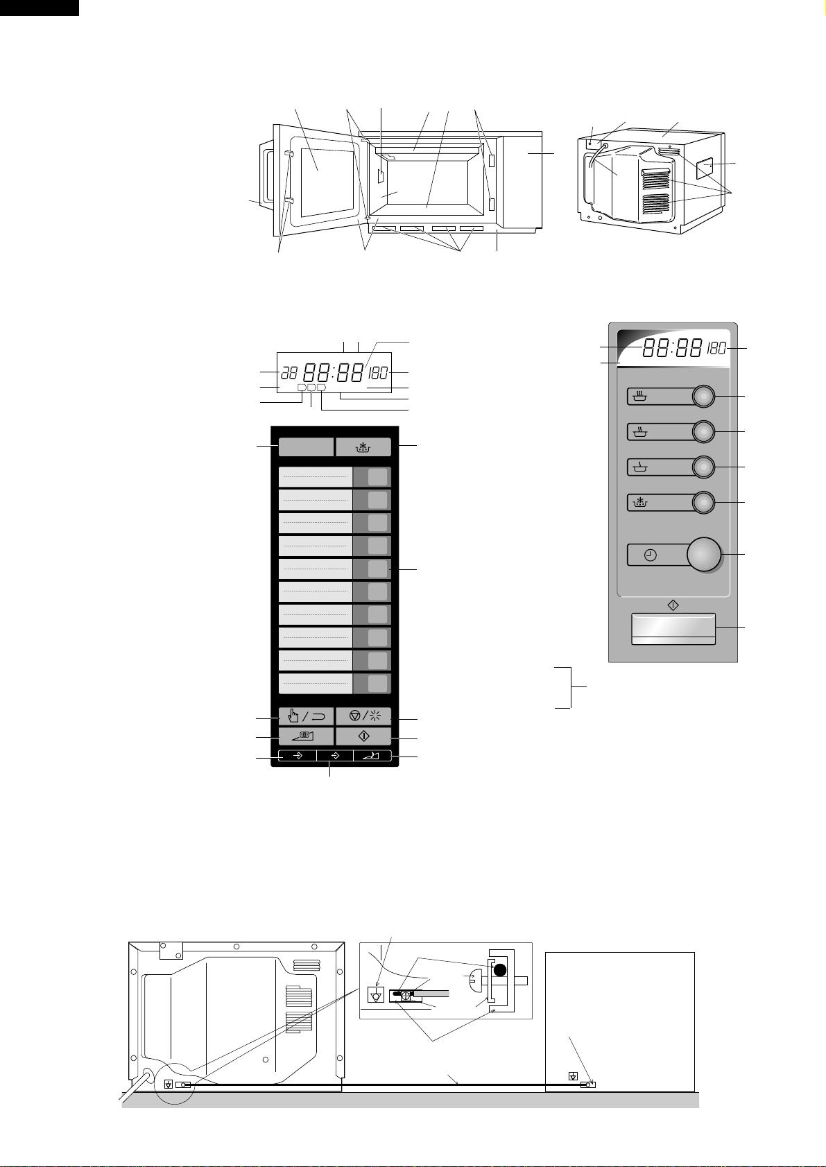
6. MONITOR SWITCH CIRCUIT
The monitor switch SW4 is mechanically controlled by
oven door, and monitors the operation of the 1st latch
switch SW1.
6-1. When the oven door is opened during or after the
cycleofacookingprogram,the1st,2nd,3rdlatchand
stopswitchesSW1+SW2+SW3+SW5mustopentheir
contactsfirst.Afterthatthecontacts(COM-NC)ofthe
monitor switch SW4 can be closed.
6-2. When the oven door is closed, the contacts (COM-
NC) of the monitor switchSW4 must be opened first.
Afterthatthecontacts(COM-NO) ofthe1st, 2nd, 3rd
latchandstopswitchesSW1+SW2+SW3+SW5must
be closed.
6-3. Whentheovendoorisopenedandthecontactsofthe
1st latch switch SW1remain closed, remains closed,
the fuse F2 F6.3A will blow, because the monitor
switch is closed and a short circuit is caused.
MICROWAVE VARIABLE COOKING (for R-23AT)
When the microwave oven is preset for variable cooking
power, the line voltage is supplied to the high voltage
Closing the door activates all door interlock switches (1st
latch switch, 2nd latch switch, 3rd latch switch and stop
switch).
IMPORTANT
Whentheovendoorisclosed,themonitorswitchcontacts
COM-NC must be open. When the microwave oven is
plugged in a wall outlet (230 volts, 50Hz), the line voltage
is suppliedto thepoint A5+A7 inthe controlpanel through
the noise filter. Figure O-1 on page 39
1. The digital display shows .
IDLE CONDITION
When the door is opened, the contacts of the 1st. latch
switchSW1,2nd.latchswitchSW2,3rd.latchswitchSW3
and stop switch SW5 open, initiating the following:
Figure O-2 on page 40
1. Asignalisinputtothecontrolunitenergizingthecoilof
shut-off relay RY-1.
2. The shut-off relay RY-1 contacts close completing
circuits to turn on the oven lamp, blower motor and
stirrer motors.
3. If the door remains open, 60 seconds later the control
unit de-energizes shut-off relay RY-1 turning off the
oven lamp, blower motor and stirrer motors.
When the door is closed, the contacts of the 1st. latch
switchSW1,2nd.latchswitchSW2,3rd.latchswitchSW3
and stop switch SW5 close. With the closing of the stop
switch SW5 contacts, an additional circuit is provided
whichwillpermittheoperationoftheovenwhenoneofthe
touch pads is depressed. Since the control is enabled
through the stop switch SW5, the door must be closed
before the touch pads will be effective. When the door is
closed,afull60secondIDLEconditionisalwaysprovided
for selecting and pressing the desired touch pads. A 60
secondIDLEconditionwillalsofollowtheendofeachcook
cycle.
MICROWAVE COOKING CONDITION
for R-23AT
Touch MANUAL/ REPEAT key and enter a desired
cookingtimewiththetouchingNUMBERkey.Andthen
touch START key.
Function sequence Figure O-3 on page 40
CONNECTED COMPONENTS RELAY
Oven lamp/ Blower motor/ Stirrer motors RY1
High voltage transformer T1 RY3
High voltage transformer T2 RY4
for R-22AM/23AM
Enter a desired cooking time with the turning ELEC-
TRONIC TIMER knob. And then push STARTbutton.
Function sequence Figure O-3 on page 40
CONNECTED COMPONENTS RELAY
Oven lamp/ Blower motor/ Stirrer motors RY1
High voltage transformer T1 RY2
High voltage transformer T2 RY3
1. The line voltage is supplied to the primary winding of

8
R-22AM
R-23AM
R-23AT
transformersT1+T2intermittentlywithina48secondtime
base through the contacts of the relays RY3+RY4.
The following levels of microwaves power are given.
NOTE: The ON/OFF time ratio does not exactly corre-
spond to the percentage of microwave power,
because approx. 3 seconds are needed for heat-
ing up the magnetron filament.
MICROWAVE VARIABLE COOKING (for R-22AM
and R-23AM)
When the microwave oven is preset for variable cooking
power, the line voltage is supplied to the high voltage
transformers intermittently within a 48 second time base
through the contacts of the relays RY2+RY3.
The following levels of microwaves power are given.
NOTE: The ON/OFF time ratio does not exactly corre-
spond to the percentage of microwave power,
because approx. 3 seconds are needed for heat-
ing up the magnetron filament.
48 sec. ON
Number key
44sec. ON
Number key 9
40 sec. ON
Number key 8
36 sec. ON
Number key 7
32 sec. ON
Number key 6
26 sec. ON
Number key 5
22 sec. ON
Number key 4
16 sec. ON
Number key 3
12 sec. ON
Number key 2
8 sec. ON
Number key 1
0 sec. ON
Number key 0
48 sec. ON
100%
26sec. ON
50%
12 sec. ON
20%
8 sec. ON
10%
T1: HIGH VOLTAGE
TRANSFORMER
H. V. RECTIFIER
C1: H.V. CAPACITOR
MG1: MAGNETRON (UPPER)
(REAR)
H. V. RECTIFIER
H. V. FUSE H. V. FUSE
C2: H.V. CAPACITOR
MG2: MAGNETRON (LOWER)
T2: HIGH VOLTAGE
TRANSFORMER (FRONT)
COMMERCIAL
FREQUENCY
(50HZ)
POWER OUTPUT
BY MAGNETRON T1
POWER OUTPUT
BY MAGNETRON T2
OPERATION OF
MAGNETRON
TWO MAGNETRON OPERATION SYSTEM
Two magnetronsMG1+MG2 are equipped in order to get
higher microwave power output. The primary windings of
the high voltage transformers T1+T2 are connected so
that each magnetron can be oscillated alternatively ac-
cording to the frequency of the power supply. Refer to the
Figure B-1 and B-2.
Figure B-1. High Voltage Circuit
Figure B-2. Operation of Magnetron

9
R-22AM
R-23AM
R-23AT
DOOR OPEN MECHANISM
1. The door release lever is pulled.
2. The upper latch head is lifted up by the linked door
release lever.
3. The head lever is lifted up by the door release lever.
4. The joint lever is lifted up by the head lever.
5. The lower latch head is lifted up by the joint lever.
6. Now both latch heads are lifted up, so they can be
released from the latch hook.
7. Now the door can be opened.
Figure D-1. Door Open Mechanism
1ST LATCH SWITCH SW1, 2ND LATCH SWITCH
SW2, 3RD LATCH SWITCH SW3 AND STOP
SWITCH
SW5
1. When the oven door is closed, the contacts COM-NO
must be closed.
2. When theoven door is opened,the contacts COM-NO
must be opened.
MONITOR SWITCH SW4
ThemonitorswitchSW4isactivated(thecontactsopened)
the upper latch head and switch lever A while the door is
closed.Theswitchisintendedtorendertheoveninopera-
tive by means of blowing the fuse F2 F6.3A when the
contacts of the 1st latch switch SW1fail to open when the
door is opened.
Function
1. When the door is opened, the monitor switch SW4
contacts close (to the ON condition) due to their being
normally closed. At this time the 1st latch switch SW1
is in the OFF condition (contacts open) due to their
being normally open contact switches.
2. As the door goes to a closed position, the monitor
switch SW4 contacts are opened and 1st latch switch
SW1 contacts are closed (On opening the door, each
of these switches operate inversely.)
3. If the door is opened and the 1st latch switch SW1
contacts failto open,thefuse F2F6.3A blowssimulta-
neously with closing of the monitor switch SW4 con-
tacts.
FUNCTION OF IMPORTANT COMPONENTS
CAUTION:BEFORE REPLACING A BLOWN FUSE F2
F6.3A TEST THE 1ST LATCH SWITCH SW1,
MONITOR SWITCH SW4 AND MONITOR
RESISTOR R1 FOR PROPER OPERATION.
(REFER TO CHAPTER “TEST PROCE-
DURE”).
MONITOR RESISTOR R1
The monitorresistorR1 prevents thefuseF2 F6.3A 250V
bursting when the fuse F 2 F6.3A 250V blows due to the
operation of the monitor switch SW4.
NOISE FILTER
The noise filter assembly prevents radio frequency inter-
ference that might flow back in the power circuit.
WEAK POINT F1
Ifthewireharnessorelectricalcomponentsmakeashort-
circuit, this weak point F1 blows to prevent an electric
shock or fire hazard.
FUSE F2 F6.3A 250V
1. If the wire harness or electrical components are short-
circuited,thisfuseblowstopreventanelectricshockor
fire hazard.
2. The fuse F2 also blows when 1st latch switch SW1
remains closed with the oven door open and when the
monitor switch closes.
FUSE(S) F3, F4 M8A
Ifthe wireharnessor thehigh voltagetransformersT1, T2
are short-circuited, these fuses F3 and /or F4 blow to
prevent an electric shock or fire hazard.
HIGH VOLTAGE FUSE(S) F5, F6
Thehighvoltagefuseblowswhenthehighvoltagerectifier
or the magnetron is shorted.
MAGNETRON TEMPERATURE FUSES TF1, TF2
The temperature fuses TF1, TF2 located on the top of the
upper and lower waveguide, are designed to prevent
damage to the magnetrons MG1, MG2. If an over heated
conditiondevelopsinthetubeduetoblowermotorfailure,
obstructed air ducts, dirty or blocked air intake, etc., the
circuit to the magnetrons are interrupted. Under normal
operation, the temperature fuses remains closed. How-
ever, when abnormally high temperatures are generated
within the magnetrons, the temperature fuses will open at
150˚C causing the microwave energy to stop. The defec-
tive temperature fuses must be replaced with new rated
ones.
OVEN TEMPERATURE FUSE TF4
The temperature fuse TF4, located on the side of the
exhaustduct assembly,isdesignedtopreventdamageto
the oven by fire. If the food load is overcooked, by either
errorincooktimeordefectinthecontrolunit,thetempera-
ture fuse will open. Under normal operation, the oven
temperature fuse remains closed. However, when abnor-
mally high temperatures are generated within the oven
Latch head
SW4: Monitor switch
Latch hook
SW1: 1st. latch switch
SW2: 2nd. latch switch
SW5: Stop switch
SW3: 3rd. latch switch
Latch head
Joint lever
Door release
lever
Head lever

10
R-22AM
R-23AM
R-23AT
cavity, the oven temperature fuse will open at 120˚C,
causingtheoventoshutdown.Thedefectivetemperature
fuse must be replaced with new rated one.
BLOWER MOTOR TEMPERATURE FUSE TF3
This temperature fuse TF3 protects the blower motor
against overheating. If its temperature goes above 120˚C
because the blower motor is stalled or the ventilation
openings are blocked, the contacts of the temperature
fusewillopen.Thelinevoltagetothecontrolunitwillbecut
off and the operation of the oven will be stopped. The
defective temperature fuse must be replaced with a new
one.
OVEN THERMISTOR (1)
The thermistor is a negative temperature coefficient type.
The temperature in the exhaust duct is detected through
the resistance of the thermistor.
If the temperature is high, the control panel will display
“EE7” and the oven will stop to avoid overheating and
catching fire.
If the thermistor is open, the control panel will display
"EE6" and the oven will stop.
OVEN THERMISTOR (2)
This thermistor detects temperature of the oven cavity
bottom plate. The thermistor is a negative temperature
coefficient type. The temperature is detected through the
resistance of the thermistor.
If the temperature is high, the control will display “EE17”
and the oven will stop.
MAGNETRON THERMISTOR
The thermistor is a negative temperature coefficient type.
The air temperature around the upper magnetron is de-
tected through the resistance of the thermistor.
If the temperature is high, the control panel will display
"EE17" and the oven will stop to protect the lower magn-
etron against overheat.
Iftheoventhermistor(2)andthemagnetronthermistorare
open at the same time, the control panel will display
"EE16" and the oven will stop.
BLOWER MOTOR BM
TheblowermotorBMdrivesabladewhichdrawsexternal
cool air into the oven. This cool air is directed through the
air vanes surrounding the magnetrons and cools the
magnetrons.Thisairischannelledthroughtheovencavity
to remove steam and vapours given off from the heating
foods. It is then exhausted through the exhausting air
vents at the oven cavity.
STIRRER MOTORS SM
Theupperand lowerstirrermotors SMdrivestirrer anten-
nas to stir the microwave radiation from the upper and
lower waveguides.
OVEN LAMP OL
Theoven cavitylight illuminatesthe interiorof theovenso
that food being cooked can be examined visually through
the door window without having to open the door. The
oven lamp is on during the cooking cycle and idle condi-
tion.
TROUBLESHOOTING GUIDE
When troubleshooting the microwave oven, it is helpful to follow the Sequence of Operation in performing the checks.
Many of the possible causes of trouble will require that a specific test be performed. These tests are given a procedure
letter which will be found in the “Test Procedure”section.
IMPORTANT: If the oven becomes inoperative because of a blown fuse F2 F6.3A in the 1st latch switch SW1- monitor
switchSW4-monitorresisitorR1circuit,checkthe1stlatchswitchSW1,monitorswitchSW4and monitor
resistor R1 before replacing the fuse F2 F6.3A

11
R-22AM
R-23AM
R-23AT
“ . “ does not appear on display when power cord is plugged into
wall outlet.
Control panel can not accept key in.
Fuse F2 F6.3A blows when the door is opened.
Home fuse blows when power cord is plugged into wall outlet.
Weak point F1 blows when power cord is plugged into wall outlet.
Oven lamp, fan motor and stirrer motors do not work for 1 minute
when the door is opened or after cooking.
Fuse F2 F6.3A blows when power cord is plugged into wall outlet.
Oven lamp does not light when door is opened. (Blower and stirrer
motors work)
Blower motor does not work when door is opened. (Oven lamp
lights and stirrer motors work)
“EE 1” (Magnetron MG1 failure)
“EE 2” (Magnetron MG2 failure)
“EE 3” (Magnetron MG1 and MG2 failure)
“EE 6” (Thermistor (1) failure)
“EE 7” (Exhaust air temperature is high)
“EE 9” (Exceeded max. heating time) for R-23AT
Oven lamp, blower motor and stirrer motors do not work.
Oven lamp does not work.
Blower motor does not work.
Oven does not stop after end of cooking cycle. (Oven lamp, blower
motor and stirrer motors stop.)
Home fuse blows when starting the oven.
Oven goes into cook cycle but shuts down before end of cooking cycle.
It passed more than 1 minute after cooking but oven lamp, blower
motor and stirrer motors do not stop.
“EE 16” (Thermistor of MG. and (2) are open.)
“EE 17” (Magnetron temperature is high.)
“EE 8” (Relay melt short)
Stirrer motors do not work.
MAGNETRON MG1
MAGNETRON MG2
HIGH VOLTAGE TRANSFORMER T1
HIGH VOLTAGE TRANSFORMER T2
H.V. RECTIFIER ASSEMBLY FOR MG1
H.V. RECTIFIER ASSEMBLY FOR MG2
H.V. WIRE HARNESS
H.V. CAPACITOR C1
H.V. CAPACITOR C2
1ST. LATCH SWITCH SW1
2ND. LATCH SWITCH SW2
3RD. LATCH SWITCH SW3
MONITOR SWITCH SW4
STOP SWITCH SW5
FUSE M8A F3
FUSE M8A F4
FUSE F13A F1
FUSE F6.3A F2
MAGNETRON TEMPERATURE FUSE TF1
MAGNETRON TEMPERATURE FUSE TF2
B. MOTOR TEMPERATURE FUSE TF3
OVEN TEMPERATURE FUSE TF4
MONITOR RESISTOR R1
MAGNETRON THERMISTOR
OVEN THERMISTOR (1)
OVEN THERMISTOR (2)
STIRRER MOTORS SM
BLOWER MOTOR BM
HIGH VOLTAGE FUSE(S) F5, F6
OVEN LAMP OR SOCKET
NOISE FILTER
POWER SUPPLY CORD
FUSE HOLDERS
Shorted wire harness
Opened wire harness
TOUCH CONTROL PANEL
RELAY RY-1
RELAY RY-3 [for R-23AT], RY2 [for R-22AM/23AM]
RELAY RY-4 [for R-23AT], RY3 [for R22AM/23AM]
FOIL PATTERN
Mis adjustment of switches
HOME FUSE or BREAKER
No power at wall outlet
Over the max. cooking time [for R-23AT]
Due to programme lock
Temperature of magnetron thermistor is high.
Temperature of oven thermistor (1) is high.
Temperature of oven thermistor (2) is high.
KEY UNIT [for R-23AT], or SWITCH UNIT [for R-22AM/23AM]
A ABBCC DDEEEEEFFGH I I I I JKKKL LN M OQQQR P
TESTPROCEDURE
POSSIBLE CAUSE
AND
DEFECTIVE PARTS
CONDITION
OFF
CONDITION
ON
CONDITION
PROBLEM

12
R-22AM
R-23AM
R-23AT
AMAGNETRON TEST
TEST PROCEDURES
PROCEDURE
LETTER COMPONENT TEST
CARRY OUT 3D CHECKS.
Isolate the magnetron from high voltage circuit by removing all leads connected to filament terminal.
Totestfor anopencircuitfilament useanohmmeter to makeacontinuity testbetweenthemagnetron
filament terminals, the meter should show a reading of less than 1 ohm.
To test for short circuit filament to anode condition, connect ohmmeter between one of the filament
terminalsandthe caseofthe magnetron(ground).This testshouldbe indicatedaninfiniteresistance.
If a low or zero resistance reading is obtained then the magnetron should be replaced.
MICROWAVE OUTPUT POWER (1 litre water load)
The following test procedure should be carried out with the microwave oven in a fully assembled
condition (outer case fitted). Microwave output power from the magnetron can be measured by way
of IEC 60705, i.e. it is measured by how much power the water load can absorb. To measure the
microwave output power in the microwave oven, the relation of calorie and watt is used. When P(W)
heating works for t(second), approximately P x t/4.187 calorie is generated. On the other hand, if the
temperature of the water with V(ml) rises ∆T (°C) during this microwave heating period, the calorie of
the water is V x ∆T.
Measuring condition:
1. Container
The water container must be a cylindrical borosilicate glass vessel having a maximum material
thickness of 3 mm and an outside diameter of approximately 190 mm.
2. Temperature of the oven and vessel
The oven and the empty vessel are at ambient temperature prior to the start the test.
3. Temperature of the water
The initial temperature of the water is (10±1)°C.
4. Selecttheinitialandfinalwatertemperaturesothatthemaximumdifferencebetweenthefinalwater
temperature and the ambient temperature is 5°C.
5. Selectstirring devicesand measuringinstrumentsinordertominimizeadditionorremovalofheat.
6. The graduation of the thermometer must be scaled by 0.1°C at minimum and be an accurate
thermometer.
7. The water load must be (1000±5) g.
8. “t”ismeasured while themicrowavegeneratoris operatingatfullpower. Magnetron filamentheat-
up time is not included.
NOTE:Theoperation timeofthe microwaveovenis“t +3”sec. (3sec.ismagnetron filamentheat-uptime.)
Measuring method:
1. Measure the initial temperature of the water before the water is added to the vessel.
(Example: The initial temperature T1 = 11°C)
2. Add the 1 litre water to the vessel.
3. Place the load on the centre of the shelf.
4. Operate the microwave oven at HIGH until the temperature of the water rises by a value ∆T of
(10 ±2) K.
5. Stir the water to equalize temperature throughout the vessel.
6. Measure the final water temperature. (Example: The final temperature T2 = 21°C)
7. Calculate the microwave power output P in watts from above formula.
NEVER TOUCH ANY PART IN THE CIRCUIT WITH YOUR HAND OR AN INSULATED TOOL
WHILE THE OVEN IS IN OPERATION.
The formula is as follows;
P x t / 4.187 = V x ∆T+ 0.55 x mc (T2-T0) P (W) = 4.187 x V x ∆T / t + 0.55 x mc (T2-T0)/t
Our condition for water load is as follows:
Room temperature (T0) ...... around 20°C Power supply Voltage.............. Rated voltage
Water load.....................................1000 g Initial temperature (T1) ...................... 10±1°C
Heating time28 sec. [R-22AM] / 23sec. [R-23AM/23AT] Mass of container (mc) .........330 g
T2............... Final temperature P = 150 x ∆T [R-22AM] / P = 180 x ∆T [R-23AM, R-23AT]

13
R-22AM
R-23AM
R-23AT
Room temperature ................................................................................................. T0 = 21°C
Initial temperature .................................................................................................. T1 = 11°C
Temperature after (28 + 3) = 31 sec [for R-22AM]................................................. T2 = 21°C
Temperature after (23 + 3) = 26 sec [for R-23AM/23AT] ....................................... T2 = 21°C
Temperature difference Cold-Warm......................................................................∆T1 = 10˚C
Measured output power
The equation is “P = 150 x ∆T” [for R-22AM] .......................... P = 150 x 10°C = 1500 Watts
The equation is “P = 180 x ∆T” [for R-23AM/23AT] ................ P = 180 x 10°C = 1800 Watts
JUDGMENT: The measured output power should be within the range of ±15 % of the rated output
power.
CAUTION: 1°C CORRESPONDS TO 150 WATTS [R-22AM]/ 180 WATTS [R-23AM, R-23AT]. REPEAT
MEASUREMENT IF THE POWER IS INSUFFICIENT.
TEST PROCEDURES
PROCEDURE
LETTER COMPONENT TEST
1000g
1000g
1000g
T1˚C T2˚C
Heat up for 31 sec. for R-22AM
Heat up for 26 sec. for R-23AM/ R-23AT
B HIGH VOLTAGE TRANSFORMER TEST
WARNING: High voltage and large currents are present at the secondary winding and
filamentwindingofthehighvoltagetransformer.Itisverydangeroustowork
near this part when the oven is on. NEVER make any voltage measurements
of the high-voltage circuits, including the magnetron filament.
CARRY OUT 3D CHECKS.
Disconnect the leads to the primary winding of the high voltage transformer. Disconnect the filament
andsecondarywindingconnectionsfrom therestoftheHV circuitry.Usinganohmmeter,set ona low
range, it is possible to check the continuity of all three windings. The following readings should be
obtained:-
If the readings obtained are not stated as above, then the high voltage transformer is probably faulty
and should be replaced.
CARRY OUT 4R CHECKS.
R-22AM R-23AM, R-23AT
a. Primary winding approximately 1.8 Ωapproximately 1.2 Ω
b. Secondary winding approximately 75 Ωapproximately 75 Ω
c. Filament winding less than 1 Ω
CARRY OUT 3D CHECKS.
Isolate the high voltage rectifier assembly from the HV circuit. The high voltage rectifier can be tested
usinganohmmetersettoitshighestrange.ConnecttheohmmeteracrosstheterminalB+Cofthehigh
voltagerectifierandnotethe readingobtained.Reversethemeter leadsandnotethissecond reading.
The normal resistance is infinite in one direction and more than 100 kΩin the other direction.
CARRY OUT 4R CHECKS.
NOTE: FOR MEASUREMENT OF THE RESISTANCE OF THE RECTIFIER, THE BATTERIES OF
THEMEASURINGINSTRUMENTMUSTHAVEAVOLTAGEATLEAST6VOLTS,BECAUSE
OTHERWISE AN INFINITE RESISTANCE MIGHT BE SHOWN IN BOTH DIRECTIONS.
C HIGH VOLTAGE RECTIFIER ASSEMBLY TEST
BC
HIGH VOLTAGE RECTIFIER

14
R-22AM
R-23AM
R-23AT
FFUSE F3, F4 M8A TEST
CARRY OUT 3D CHECKS.
IfthefusesF3and/or F4M8Aareblown,therecouldbeshortsinthehighvoltagetransformersT1 and/
orT2 or thereisa groundin wireharness.Check and/or replacethehigh voltagetransformersT1and/
or T2 or repair the wire harness.
CARRY OUT 4R CHECKS.
CAUTION: Only replace fuses F3, F4 M8A with the correct value replacement.
GWEAK POINT F1 TEST
CARRY OUT 3D CHECKS.
If the weak point F1 is blown, there could be a shorts or grounds in electrical parts or wire harness.
Check them and replace the defective parts or repair the wire harness.
CARRY OUT 4R CHECKS.
CAUTION: Only replace weak point F1 with the correct value replacement.
If incorrect readings are obtained, make the necessary switch adjustment or replace the switch.
CARRY OUT 4R CHECKS.
H FUSE F2 F6.3A TEST
CARRY OUT 3D CHECKS.
IfthefuseF2F6.3Aisblownwhenthedoorisopened,checkthe1st.latchswitchSW1,monitorswitch
SW4 and monitor resistor R1.
If the fuse F2 F6.3A is blown by incorrect door switching replace the defective switch(s) and the fuse
F2 F6.3A.
CARRY OUT 4R CHECKS.
CAUTION: Only replace fuse F2 F6.3A with the correct value replacement.
TEST PROCEDURES
PROCEDURE
LETTER COMPONENT TEST
ESWITCH TEST
CARRY OUT 3D CHECKS.
Isolate the switch to be tested and using an ohmmeter check between the terminals as described in
the following table.
D HIGH VOLTAGE CAPACITOR TEST
CARRY OUT 3D CHECKS.
A. Isolate the high voltage capacitor from the circuit.
B. Continuity check must be carried out with measuring instrument which is set to the highest
resistance range.
C. A normal capacitor shows continuity for a short time (kick) and then a resistance of about 10MΩ
after it has been charged.
D. A short-circuited capacitor shows continuity all the time.
E. An open capacitor constantly shows a resistance about 10 MΩbecause of its internal 10MΩ
resistance.
F. When the internal wire is opened in the high voltage capacitor shows an infinite resistance.
G. The resistance across all the terminals and the chassis must be infinite when the capacitor is
normal.
If incorrect reading are obtained, the high voltage capacitor must be replaced.
CARRY OUT 4R CHECKS.
Table: Terminal Connection of Switch
Plunger Operation COM to NO COM to NC
Released Open circuit Short circuit
Depressed Short circuit Open circuit
COM; Common terminal,
NO; Normally open terminal
NC; Normally close terminal

15
R-22AM
R-23AM
R-23AT
TEST PROCEDURES
PROCEDURE
LETTER COMPONENT TEST
1. CARRY OUT 3D CHECKS.
2. Acontinuitycheckacrossthetemperaturefuseterminalsshouldindicateaclosedcircuitunlessthe
temperature of the temperature fuse reaches specfied temperature as shown below.
ITEMPERATURE FUSE TEST
3. CARRY OUT 4R CHECKS.
CAUTION: IF THE temperature fuse INDICATES AN OPEN CIRCUIT AT ROOM TEMPERATURE,
REPLACE temperature fuse.
Open Close Display or
temperature temperature Condition Check point
Magnetron tem-
perature fuse TF1
Magnetron tem-
perature fuse TF2
Blower motor tem-
perature fuse TF3
Oven temperature
fuse
TF4
150˚C
120˚C
120˚C
Non resetable
type
Non resetable
type
Non resetable
type
EE1
EE3
EE2
Oven shut
off
Oven shut
off
Magnetron
MG1 Failure:
Test magnetron MG1 and Blower fan motor.
Magnetron MG1, MG2 Failure: Test magnetron MG1,
MG2. Check blower fan motor and ventilation opening.
Magnetron MG2 Failure:
Test magnetron MG2 and Blower fan motor.
Check blower fan motor and ventilation opening or
rocked rotating of blower fan motor.
Food has been burned in oven.
Temperature of oven inside is very high.
J MONITOR RESISTOR R1 TEST
CARRY OUT 3D CHECKS.
Disconnecttheleads fromthemonitor resistorR1. Usinganohmmeter andseton alowrange. Check
between the terminals of the monitor resistor R1.
The resistance of monitor resistor R1 should be read approx. 4.3Ω.
If incorrect readings are obtained, replace the monitor resistor R1.
CARRY OUT 4R CHECKS.
1. CARRY OUT 3D CHECKS.
2. Follow the procedures below for each thermistor.
2-1. MAGNETRON THERMISTOR TEST
Disconnect the connector of the magnetron thermistor from the switch harness. Measure the
resistance of the magnetron thermistor with an ohmmeter. Connect the ohmmeter leads to the leads
of the thermistor.
Room Temp. 59˚F (15˚C) 68˚F (20˚C) 77˚F (25˚C)
Resistance Approx. 373 kΩApprox. 292 kΩApprox. 231 kΩ
If the meter does not indicate above resistance, replace the thermistor.
2-2. OVEN THERMISTOR (1) TEST
Disconnect the connector of the oven thermistor (1) from the switch harness. Measure the resistance
oftheoventhermistor(1)withanohmmeter.Connecttheohmmeterleadstotheleadsofthethermistor.
Room Temp. 59˚F (15˚C) 68˚F (20˚C) 77˚F (25˚C)
Resistance Approx. 373 kΩApprox. 292 kΩApprox. 231 kΩ
If the meter does not indicate above resistance, replace the thermistor.
2-3. OVEN THERMISTOR (2) TEST
Disconnect the two connectors of the magnetron thermistor and oven thermistor (2) from the switch
harness.Measure theresistanceoftheoventhermistor(2)withanohmmeter.Connecttheohmmeter
leads to the leads of the thermistor.
KTHERMISTOR TEST

16
R-22AM
R-23AM
R-23AT
Room Temp. 59˚F (15˚C) 68˚F (20˚C) 77˚F (25˚C)
Resistance Approx. 16 kΩApprox. 13 kΩApprox. 11 kΩ
If the meter does not indicate above resistance, replace the thermistor.
3. CARRY OUT 4R CHECKS.
O TOUCH CONTROL PANEL ASSEMBLY TEST FOR R-23AT
If incorrect readings are absorbed, replace the noise filter.
CARRY OUT 4R CHECKS.
N HIGH VOLTAGE FUSE TEST
CARRY OUT 3D CHECKS.
If the high voltage fuse is blown, there could be a short in the high voltage rectifier or the magnetron.
Check them and replace the defective parts and the high voltage fuse.
CARRY OUT 4R CHECKS.
CAUTION: Only replace high voltage fuse with the correct value replacement.
TEST PROCEDURES
PROCEDURE
LETTER COMPONENT TEST
LMOTOR WINDING TEST
CARRY OUT 3D CHECKS.
Disconnect the leads from the motor. Using an ohmmeter, check the resistance between the two
terminals.
Resistance of Blower motor should be approximately 52Ω.
Resistance of Stirrer motor should be approximately 8.8 kΩ.
If incorrect readings are obtained, replace the motor.
CARRY OUT 4R CHECKS.
M NOISE FILTER TEST
CARRY OUT 3D CHECKS.
Disconnect the leads from the terminals of noise filter. Using an ohmmeter, check between the
terminals as described in the following table.
MEASURING POINT INDICATIONOFOHMMETER
Between N and L Approx. 680 kΩ
Between terminal N and WHIT Short circuit
Between terminal L and BLK Short circuit
F1 : WEAK POINT
NOISE FILTER
NOISE SUPPRESSION COIL
DISCHARGE RESISTOR 680 kΩ1/2W
DISCHARGE RESISTOR 10 MΩ1/2W
LINE CROSS CAPACITOR 0.22µF/ AC250V
LINE CROSS CAPACITOR
10000 pF/ AC250V LINE CROSS CAPACITOR
10000 pF/ AC250V
L
BLK
WHT
N
The touch control panel consists of circuits including semiconductors such as LSI, IC, etc. Therefore,
unlikeconventionalmicrowaveovens,propermaintenancecannotbeperformedwithonlyavoltmeter
and ohmmeter. In this service manual, the touch control panel assembly is divided into two units,
ControlUnitandKeyUnit,troubleshootingbyunitreplacementisdescribedaccordingtothesymptoms
indicated.
1. Key Unit Note : Check key unit ribbon connection before replacement.
The following symptoms indicate a defective key unit. Replace the key unit.
a) When touching the pads, a certain pad produces no signal at all.
b) When touching the pads, sometimes a pad produces no signal.
2. Control Unit
The following symptoms may indicate a defective control unit. Replacing the control unit. Before
replacingthecontrolunit,performthekeyunittest(ProcedureP)todetermineifcontrolunitisfaulty.
2-1 Programming problems.
a) When touching the pads, a certain group of pads do not produce a signal.

17
R-22AM
R-23AM
R-23AT
TEST PROCEDURES
PROCEDURE
LETTER COMPONENT TEST
2-2 Display problems.
a) For a certain digit, all or some segments do not light up.
b) For a certain digit, brightness is low.
c) Only one indicator does not light.
d) The corresponding segments of all digits do not light up; or they continue to light up.
e) Wrong figure appears.
f) A certain group of indicators do not light up.
g) The figure of all digits flicker.
2-3 Other possible problems caused by defective control unit.
a) Buzzer does not sound or continues to sound.
b) Cooking is not possible.
CONTROL PANEL ASSEMBLY TEST FOR R-23AM / R-22AM
The control panel consists of circuits including semiconductors such as LSI etc. Therefore, unlike
conventional microwave ovens, proper maintenance cannot be performed with only a voltmeter and
ohmmeter. In this service manual, the touch control panel assembly is divided into three units, Control
Unit, Switch Unit and Encoder Unit troubleshooting by unit replacement is described according to the
symptoms indicated.
1. Switch Unit Note : Check the lead wire harness connections among big and small switch units
and control unit before replacement.
The following symptoms indicate a defective switch unit. Replace the switch unit.
a) When touching the buttons, a certain button produces no signal at all.
b) When touching the buttons, sometimes a button produces no signal.
2. Encoder Note : Check the lead wire connection between encoder and control unit before
replacement.
The following symptoms indicate a defective encoder. Replace the encoder.
a) When rotating the encoder, the cooking time can not be entered.
3. Control Unit
The following symptoms may indicate a defective control unit. Replacing the control unit. Before
replacing the control unit, perform the switch unit test (Procedure P) to determine if control unit is
faulty.
3-1 Programming problems.
a) When touching the buttons, a certain group of buttons do not produce a signal.
3-2 Display problems.
a) For a certain digit, all or some segments do not light up.
b) For a certain digit, brightness is low.
c) Only one indicator does not light.
d) The corresponding segments of all digits do not light up; or they continue to light up.
e) Wrong figure appears.
f) A certain group of indicators do not light up.
g) The figure of all digits flicker.
3-3 Other possible problems caused by defective control unit.
a) Buzzer does not sound or continues to sound.
b) Cooking is not possible.
CARRY OUT 3D CHECKS.
If the display fails to clear when the STOP/CLEAR pad is depressed, first verify the flat ribbon cable is
making good contact, verify that the door sensing switch (stop switch ) operates properly; that is the
contactsareclosedwhenthedoorisclosedandopenwhenthedoorisopen.Ifthedoorsensingswitch
(stopswitch)isgood,disconnect the flat ribbon cable thatconnectsthekeyunit to the control unit and
make sure the door sensing switch is closed (either close the door or short the stop switch connector
). Use the key unit matrix indicated on the control panel schematic and place a jumper wire between
the pins that correspond to the STOP/CLEAR pad making momentary contact. If the control unit
responds by clearing with a beep, the key unit is faulty and must be replaced. If the control unit does
not respond, it is faulty and must be replaced. If a specific pad does not respond, the above method
may be used (after clearing the control unit ) to determine if the control unit or key pad is at fault.
P KEY UNIT TEST FOR R-23AT

18
R-22AM
R-23AM
R-23AT
CARRY OUT 3D CHECKS.
Removetheoutercaseand checkvoltagebetweenPinNos.5and7ofthe connector(A)onthecontrol
unit with an A.C. voltmeter. The meter should indicate 230 volts, if not check control unit circuity.
RY1, RY3 and RY4 Relay Test For R-23AT
These relays are operated by D.C. voltage.
Check voltage at the relay coil with a D.C. voltmeter during the microwave cooking operation.
DC. voltage indicated.............................Defective relay.
DC. voltage not indicated .......................Check diode which is connected to the relay coil. If
diode is good, control unit is defective.
RELAY SYMBOL OPERATIONAL VOLTAGE CONNECTED COMPONENTS
RY1 APPROX. 19.0V D.C. Oven lamp, Blower motor and Stirrer motors
RY3 APPROX. 16.0V D.C. High voltage transformer 1
RY4 APPROX. 18.0V D.C. High voltage transformer 2
RY1, RY2 and RY3 Relay Test For R-23AM / R-22AM
These relays are operated by D.C. voltage.
Check voltage at the relay coil with a D.C. voltmeter during the microwave cooking operation.
DC. voltage indicated.............................Defective relay.
DC. voltage not indicated .......................Check diode which is connected to the relay coil. If
diode is good, control unit is defective.
TEST PROCEDURES
PROCEDURE
LETTER COMPONENT TEST
QRELAY TEST
CARRY OUT 4R CHECKS.
SWITCH UNIT TEST FOR R-23AM / R-22AM
1. CARRY OUT 3D CHECKS.
2. Remove the switch unit from the control panel, referring to control panel removal.
3. To test the switches (SW1-SW5) on the switch unit, check between the terminals of the connector
CN-F as described in the following table by using ohmmeter when the switches are released and
depressed.
Switches Terminals Released Depressed
SW1 F1 - F4 O.C. S.C.
SW2 F1 - F5 O.C. S.C.
SW3 F2 - F4 O.C. S.C.
SW4 F2 - F5 O.C. S.C.
SW5 F3 - F4 O.C. S.C.
4. If incorrect readings are obtained, replace the defective switch.
5. CARRY OUT 4R CHECKS.
G 9
G 10
G 11
G 12
G 8
1
11
12
13
14
15
16
19
20
17
18
2
3
4
5
6
7
8
9
0
G 7 G 6 G 5 G 4 G 3 G 2 G 1
X2
Other manuals for R-22AM
1
This manual suits for next models
2
Table of contents
Other Sharp Microwave Oven manuals

Sharp
Sharp R-67STM Instruction Manual

Sharp
Sharp R-830B User manual

Sharp
Sharp R-402FW User manual

Sharp
Sharp R-305EW User manual

Sharp
Sharp SMD2480CSC User manual

Sharp
Sharp R-242E User manual

Sharp
Sharp R-820EBK User manual

Sharp
Sharp R-272M User manual

Sharp
Sharp R-408EW User manual

Sharp
Sharp R-222R User manual

Sharp
Sharp R-410HK User manual

Sharp
Sharp Carousel II R-8570 User manual

Sharp
Sharp R-320BB User manual

Sharp
Sharp R-23AM User manual

Sharp
Sharp R-395E User manual

Sharp
Sharp R-252M Instruction Manual

Sharp
Sharp R-1210TYA User manual

Sharp
Sharp R-354M Instruction Manual

Sharp
Sharp R-3S68 User manual

Sharp
Sharp R-408JK User manual