Sharp R-9X55 User manual

SHARP SERVICE MANUAL S3301 R9X55J//
CONVECTION
MICROWAVE OVEN
MODEL R-9X55
In interests of user-safety the oven should be restored to its original condi-
TABLE OF CONTENTS page
GENERAL IMPORTANT INFORMATION ...................................................................................................... 1
WARNING ...................................................................................................................................................... 1
RODUCT SPECIFICATIONS ......................................................................................................................... 2
APPEARANCE VIEW .................................................................................................................................... 3
OPERATING SEQUENCE ............................................................................................................................. 4
FUNCTION OF IMPORTANT COMPONENTS’ ............................................................................................ .8
TRABLESHOOTING CHART.. .................................................................................................................... .I1
TEST PROCEDURE .................................................................................................................................... 14
TOUCH CONTROL PANEL ........................................................................................................................ .24
COMPONENT REPLACEMENT AND ADJUSTMENT PROCEDURE ....................................................... 31
MICROWAVE MEASUREMENT .................................................................................................................. 38
WIRING DIAGRAM ...................................................................................................................................... 39
PICTORIAL DIAGRAM ................................................................................................................................ 41
CONTROL PANEL CIRCUIT ...................................................................................................................... .42
PRINTED WIRING BOAD ............................................................................................................................ 43
PARTS LIST ................................................................................................................................................ .44
SHARP CORPORATION
L


SERVICE MANUAL
SHARP
MICROWAVE OVEN
R-9X55
GENERAL IMPORTANT INFORMATION
This Manual has been prepared to provide Sharp Corp. Service
engineers with Operation and Service Information.
It is recommended that service engineers carefully study the en-
tire text of this manual, so that they will be qualified to render sat-
isfactory customer service.
CAUTION
MICROWAVE RADIATION
Service engineers should not be exposed to the microwave en-
ergy which may radiate from the magnetron or other microwave
generating devices if it is improperly used or connected. All in-
put and output microwave connections, waveguides, flanges
andgaskets must be secured. Never operate the device without
a microwave energy absorbing load attached. Never look into
an open waveguide.
WARNING
Never operate the oven until the following points are ensured.
.
(A) The door is tightly closed.
(B) The door brackets and hinges are not defective.
(C) The door packing is not damaged.
(D) The door is not deformed or warped.
(E) There is not any other visible damage with the oven.
Servicing and repair work must be carried out only by trained
service engineers.
All the parts marked “*” on parts list are used at voltages more
than 25OV.
Removal of the outer wrap gives access to potentials above
25ov.
SHARP CORPORATION
OSAKA, JAPAN
1

PRODUCT SPECIFICATIONS \
ITEM
Power Requirements 240 Volts
50 Hertz
DESCRIPTION
Power Consumption
Power Output
Convection heating element
Case Dimensions
Single phase, 3 wire earthed
1600 W (Microwave)
1600 W (Convection)
800 watts nominal of RF microwave energy (2 litre water load)
900 watts (IEC-705-1988 )
Operating frequency of 2450MHz
1500 w
Width 627mm
Height 381 mm
Depth 527mm
Cooking Cavity Dimensions
Control Complement
Width 41Omm
Height 245mm
Depth 41Omm
Touch Control System
Clock ( I:00 - 12:59)
Timer (0 - 99 min. 99 sec.)
Microwave Power for Variable Cooking
Repetition Rate;
HIGH ...............................................Full power throughout the cooking time
MED HIGH (MEDIUM HIGH) .............................approx. 70% of Full Power
MED (MEDIUM) ..................................................approx. 50% of Full Power
MED LOW (MEDIUM LOW/DEFROST) .............approx. 30% of Full Power
LOW .............*.*.................................................... approx. 10% of Full Power
Convection Temperature for Variable Cooking
CONVECTION ....................................................40 to 250°C Temp. control
LOW MIX(BAKE) ................................180°C with
HIGH MIX(ROAST) 10% of microwave power
............................200°C with 30% of microwave
GRILL power
..................................................................................250°C (Preheat)
INTELLIGENT SENSOR pad
DEFROST SENSOR pad
WEIGHT ADJUST pad
REHEAT SENSOR pad
SENSOR INSTANT ACTION pads
CONVECTION COOKING pad
FUNCTION pad
NUMBER and TEMPERATURE pads
POWER LEVEL pad --
MORE. LESS pads
STOP/CLEAR pad
AUTO START/CLOCK pad
Set Weight INSTANT COOK/START pad
Approx. 31 kg

APPEARANCE VIEW
1. Oven lamp
2. Door hinges
3. Door sefty latches
4. See through door
5. Touch Control Panel
6. Digital readout
7. Waveguie cover
8. Covvection air openings
sensor and Reheat sensor
10. Access cover for oven
lamp replacement
11. Ventilation openings
12. Low rack
13. High rack
14. Defrost rack
Turntable
Tarntable stipoort plate ---‘!%Z?,~
DISPLAY
Micro/Defrost
TOUCH CONTROL PANEL INTELKENT SENSL’R ?,AC
Press ?o se!ec: ;;opular Convect!or. fvi.;
Grill and Mlcrc cocking menus wit? t~e!sr:
sensor or hum;dl?y (AH) seqscr
.
f FiEHEART “I
jSE~s0Fi /i REHEAT SENSOR PAD
Press to select 3 popular Rsneat rnerus
with humidity (AH) sensor.
WEIGHT ADJUST PAD
Press to zero the weight of your own
dishes before cooking with weight
DEFROST SENSOR PAD
Press to defrost meat, popular or seafood
automatically with weight sensor
sensor.
POWER LEVEL PAD
Press to select microwave power set-
ting. If not pressed, HIGH is automati-
cally selected.
NUMBER AND TEMPERATURE PADS
Press to enter cooking times, clock
time, convection temperature or to
select the intelligent Sensor menus.
AUTO START/CLOCK PAD -
Press to set clock or Auto Start time.
1 1
,-POWER LEVEL ,-MORE, LESS PADS
Press to increase/decrease ?he time In one
minute increments during cooklng or alter
thedoneness for the Sensor lnsatnt Action,
STOP/CLEAR PAD !
Press to clear during programming.
Press once to stop operation of oven
during cooking; press twice to cancel
cooking programme.
7
I f
/ I I
LOW MIX/HIGH Mlq GRILL CONVEC
CONVECTION COOKING FUNCTION PADS
Press to cook for each function.
increase by 1 minute multrples each time
this pad is pressed during cooktng. Press to
start oven after setting programmes.

OPERATION SEQUENCE
OFF CONDIITION
Closing the door activates all door interlock switches
(Right latch switch. Left latch switch and stop switch.)
IMPORTANT
When the oven door is closed. the monitor switch contacts
COM-NC must be open.
When the microwave oven is plugged in a wall outlet (240V
50Hz). 24Ovolts A.C. is supplied to the point A7+A9 in the
control unit. Figure O-t on page 39
1. The display flashes “88:88”.
2. To set any programmes or set the clock, you must first
touch the STOP/CLEAR key.
3. ” : ” appears in the display and the time counts up every
minute.
NOTE:When the oven door is opened, the oven lamp comes
on at this time.
MICROWAVE COOKING CONDITION
HIGH COOKiNG
Enter a desired cooking time with the touching NUMBER key
and star: the oven with touching START key.
Function sequence Figure O-2 on page 39
CONNECTED COMPONENT SRELAY
&ei: lamp. Turntable motor iPower transformer-i RY:
3vei iraxformer R\i’2
-_- .---
Far, --qg:fJ: RY6
A La:, volis F.C. is sdppl~ed :o rI-~eprimary windli7o oi the
3 ,-,I*‘,’G !I l .-
- _ _ a-7sio:mer ‘rie at:agc is c0nver~e.d ?c aGout 3.3
-.,irCI r>
”..*‘*I_---cL‘ ,3J;piJ: 33 Lb r’c
t$iemament wrndlng and high voltage
,L
SJ~~~~~~~imafeiif Xlr)“-
-, ^LLL volts A.C on the sec’3nclar:*t wind-
-,2
.L ->e i‘lI2~ifr,: iJ~;!~~fi’,gvG!tage ;Z.fq volts; heals the i’;a~x-
*v-.-f f;iar,er,t and Ihe nic~kvoI:aoe (2NcI volts: 1sse;? to
%‘, voltaoe doubiina circui?. wh&e it is doubled to nega-
xw :.oltaie oi appr&maiety 0OG volts 2.C..
P
2 y-h;
u Z&;! MI+Z microwave energy produced in the mag-
re?ro!r, generap =(
“L u wave length of 12.24 cm. This energy
.r
I-- 9,anneled through the waveguide (transport channel\
inI0 the oven cavity. where tile food is placed ?o be
,zooked.
4. lrdhen the cooking time is up. a srgnai tone is heard and
the relays (RY! +RY2+RY6) go back to their home posi-
tion. The circuits to the oven lamp. power transformer. fan
motor and turntable motor are cut off.
5. When the door is opened during a cook cycle. the
switches come to the following condition.
Condition
During Oven Door
Switch Contact Cooking Open( No cooking j
Righ Latch Switch COM-NO Closed Open
Monrtor Switch COM-NC Open Closed
Left Latch Switch COM-NO Closed
Stop Switch Open
OM-NO Ciosed 3pen
6
The circuits to the power transformer and turntable
motor are cut off when the right latch switch and left
latch switch are made open. The fan motor is cut off
when the stop switch is made open.
The oven lamp remains on even if the oven door is
opened after the cooking cycle has been inter-
rupted, because the relay (RYl) stays closed.
Shown in the display is the remaining time.
MONITOR SWITCH CIRCUIT
The monitor switch is mechanically controlled by
oven door. and monitors the operation of the right
latch switch and left latch switch.
6-1
6-2.
6-3.
When the oven door is opened during or after the
cycle of a cooking program, the contacts (COM-
NC) of the monitor switch must be closed and the
contacts (COM-NO) of the righ latch switch, left
latch switch and stop switch must be opened at
the same time.
When the oven door is closed. the contacts (COM-
NC) of the monitor switch must be opened and
the contacts (COM-NO) of the righ latch switch,
ieft latch switch and stopswitch must be closed at
the same time.
When the oven door is opened and the contacts of
the right latch switch and the left latch switch
remain closed. the fuse M8A will blow, because
t9e monitor switch and relay (RYl) are closed and
a short cirsu~l is caused.
MEDIUM HIGH. MEDNM, MEDIUM LOW. LOW
COOKING
V~hen the microwave oven is preset for variable cook-
izg power, 240 volts AC Dower is supplied to the
pOWe 7 rransformer intermittently within a 32-second
trme tjase throuab the relay contact which is coupled
with :ne current-limlt/ng relay RY2. The foliowrng levels
oi microwave poiver are given.
32sec ON
-;r -
21E3 -’ hi4r: s I-
18sec ON 14 set OFF
I.1E3 u hl J] Armor 50%
i2sec ON 2Gsec OFE
VEDIdY -0w Dy Apvoj 30%
6 set ON
,OVi
l-1 Approh10%
NOTEThe ON/OFF time ratio does not exactly corre-
spond to the percentage of microwave power,
because approx. 2 seconds are needed for
heating up the magnetron filament.

R-9X55
CONVECTION COOKING CONDITION
PREHEATING CONDITION
Program desired convection temperature by touching
the CONVECTION pad and the temp. pad. When the
START pad is touched, the following operations occur:
1. The coil of shut-off relays RYI +RY5+RY6 are
energizedthe oven lamp, cooling fan motor. turn-
table motor and convection motor are turned on.
2. The coil of relay (RY4) is energized by the CPU unit.
The damper is moved to the closed position open-
ing the damper switch contacts. The opening of the
damper switch contacts sends a signal to the LSI on
the CPU unit de-energizing the relay (RY4) and
opening the circuit to the damper motor.
3. The coil of heater relay (RY3) is energized by the
CPU unit and the main supply voltage is added to
the convection heater.
4. When the oven temperature reaches the selected
preheat temperature, the following operations occur:
4-1. The heater relay (RY3) is de-energized by the
CPU unit temperature circuit and thermistcr, operr-
ing the circuit to the convection heater.
4-2. The oven wiil continue to function for 15 minutes.
turning the convection heater on and off. as
needed to maintain the selected preheat tempera-
ture. The oven will shut-down completely after 15
minutes.
CONVECTION COOKING CONDITION
When the preheat temperature is reached, a beep sig-
nal will sound indicating that the holding temperature
has been reached in the oven cavity. Open the door and
place the food to be cooked in the oven. Program de-
sired cooking time and convection temperature by
touching the number pad, CONVECTION pad and
Temperature pad. When the START pad is touched,
the following operations occur:
1.
2.
3.
4.
5.
The numbers of the digital readout start the count
down to zero.
The oven lamp, turntable motor, cooling fan motor
and convection motor are energized.
Heater relay (RY3) is energized (if the cavity tem-
perature is lower than the selected temperature) and
the main supply voltage is applied to the convection
heater to return to the selected cooking temperature.
Upon completion of the cooking time, the audible
signal will sound, and oven lamp, turntable motor,
cooling fan motor and convection motor are de-ener-
gized. At the end of the convection cycle, if the cavity
air temperature is above 118°C the circuit to (RY6)
will be maintained (by the thermistor circuit) to con-
tinue operation of the cooling fan motor until the
temperature drops below 118°C at which time the
relay will be de-energized, turning off the fan motor.
Relay (RY5) will however, open as soon as the con-
vection cycle has ended, turning off the convection
fan motor. This will now cool and allow the damper
door to open.
At the end of the convection cook cycle, shut-off re-
lay (RY4) is energized turning on the damper motor.
The damper is returned to the open position, closing the
damper switch contacts which send a signal to the control
unit, de-energizing shut-off relay (RY4).
MIX COOKING CONDITION
Program desired cooking time and temperature by Touching
the number pads and the LOW MIX’BAKE or !ilGH MIX
ROAST pad. When the START pad is touched, the following
operations occur:
1. The numbers of the digital readout start the count dcwn to
zero.
2. The shut-off relay (RYl i-RY%RYE) energized. iurr~ng or
the oven lamp. turntable motor. cocling fan moTor anti
convection motor.
3. The shut-off re!ay (RY4) is energrzec.
The damper door is closed from the open positicn
4. The heater relay (RYS; IS energized. addirx ?-2 -x:~c
stipply voltage to the convectron heater.
5. Now. the oven is in the convecticn cooking x~r:~r~cr
6. When the oven temperature reacnes t?e ~ete,::?~: ye’:-
perature. the following operations -c-p
“AdtAr
6-l. The power supply !/o!tagrs :s.adcec: :Z :?< :~;‘~~~~::;::r
heater a.pd power transformer ati?e-r~~:r?I
6-2. The ,convection heater operates :n:o:.,:r;r’ 7’;~ ,-?.;+z- r-
lay IRY3; ccntacts and tpe ;csyer :ra~~:cy--+- :~~:z;.: :
throuah the cook ieiav PY2‘: con;acts
6-3. These are operated by the tspiL[ iJ”j’ ‘,P
L ;!LDj ‘, 3;1:---
nateiy within a 32 second time bass co? ,z:& ?e,::
and microwave energy.
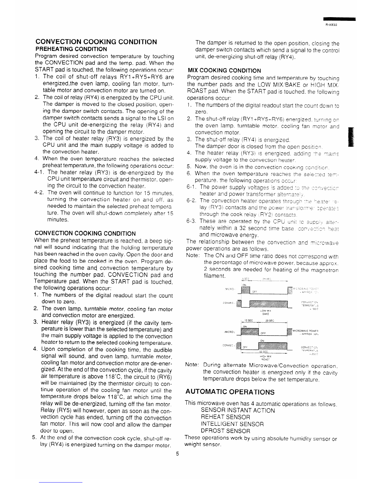
The relationship between the convection sr;cJ ?-1;:‘;1i
j w,va+;;j
power operations are as follows.
Note: The ON and OFF time ratro does not eorresoond with
the percentage of microwave power. because appro:c.
2 seconds are needed for heating of the magnetrcn
filament. _SE-
_ ., -5>E.
--~~-. --~---~ ~~..._
_-
SAYE
/ ‘?SEC 20SEC
ON
iwcao / VICRCWAVE JOivFii
3FF i eiwciox 3:“.
ON
ccr.vEz- i.,
Note: During alternate MicrowaveConvection operation,
the convection heater is energized only if the cavity
temperature drops below the set temperature.
AUTOMATIC OPERATIONS
This microwave oven has 4 automatic operations as follows.
SENSOR INSTANT ACTION
REHEAT SENSOR
INTELLIGENT SENSOR
DFROST SENSOR
These operations work by using absolute humidity sensor or
weight sensor.

ABSOLUTE HUMIDITY SENSOR (AH SENSOR) COOK-
ING CONDITION
lncase where the AH sensor is used, the foods are cooked in
microwave cooking mode without figuring time, power level
or quantity. When the oven senses enough steam from the
food, it relays the information to its microprocessor which will
calculate the remaining cooking time and power level
needed for best results.
When the food is cooked, water vapor is developed. The
sensor “senses” the vapor and its resistance increases
gradually. When the resistance reaches the value set ac-
cording to the menu, supplementary cooking is started.
The time of supplementary cooking is determined by experi-
ment with each food category and inputted into the LSI.
An example of how sensor works:
1. Potatoes at room temperature. Vapor is emitted very
slowly.
2. Heat potatoes. Moisture and humidity is emitted rapidly.
You can smell the aroma as it cooks. :
3. Sensor detects moisture and humidity and calculates
cooking time and variable power.
AH SENSOR COOKING SEQUENCE
1. In case the AH sensor cooking condition is started. the
coil of shut-off relays (RYl +RYG) are energized, the oven
lamp and cooling fan motor are turned on, but the power
transformer is not turned on.
NOTE:The oven should not be operated on AH SENSOR
COOKING immediately after plugging in the unit. Wait
five minutes before cooking on AH SENSOR COOK-
ING CONDITION.
2. After about 16 seconds, the cook relay (RY2) is ener-
gized. The power transformer is turned on, microwave
energy is produced and first stage is started. The 16 sec-
onds is the cooling time required to remove any vapor
from the oven cavity and sensor.
Figure O-2
NOTE:During this first stage, do not open the door or touch
STOP/CLEAR pad.
3. When the sensor detects the vapor emitted from the food,
the display switches over to the remaining cooking time
and the timer counts down to zero.At this time, the
door may be opened to stir food, turn it or season,
etc.
NOTE: In case where a small quantity of food is cooked,
the oven will stop without displaying the remain-
ing cooking time.
4. When the timer reaches zero, an audible signal
5
sounds. The shut-off relay (RYl+RYG) and cook re-
lay (RY2) are de-energized and the power trans-
former. oven lamp, etc. are turned off.
Opening the door or touching the STOP/CLEAR
pad. the time of day will reappear on the display and
the oven will revert to an OFF condition.
WEIGHT SENSOR COOKING CONDITION
In case where the weight sensor is used, the foods are
cooked without figuring cooking mode, time. power lev-
elor weight.
When the oven senes the weight of food, it relays the
information to its microprosessor which will set the
cooking mode and will calculate the cooking time and
power level needed for best results.
ACTIVATED SENSOR FOR SENSOR COOKING
The weight sensor and AH. sensor should be worked as
following table.
I Sensor ; IWetaht /AH.~
CookIng j Menu
’ Roas! beef. 3oast beef drnner
SENSOR Roast lamb. Roast lamb dinner
IRS--ANT Roast cnwen. Grilled fish
ISensor /Sensor
/ 83 I
’ 3 1
?
-
ACTI3V !?3ast ChicKen dinner. Reheat pte ’ /
3 I
Fresh vegeaale. racket ootato j 3
i SE’\iS3;i Severaae. Souc 7 /
1 q”+LA-
I- L 13;nner piate. Casserole ! I
, ,z
, cannecl fooo I ’ c
, ?eneat pizza. Seasonea roast I 2 1
iioasi :urkey. Roast pork ?
I L.-J
Grilled steak’Crlop.s, &wits / ,--Y /
../
Sriiled Ye3abs. i;osst vegetable ; 2
C:ozerl bfeaetables. Casserole 7 ?
j SEP,S32 -
rish flile:s:‘orneo meat
See Pasta. Dessefls
, Soup. Preseives.
t?EEFiOST All merltis
I S=ti$,cR /
The menu “Cake” does not useneither the weight sen-
sor nor the Ah sensor.
SENSING FIRE OPERATION
The oven will stop its operation when there is a fire in
the oven cavity in microwave cooking condition.
LSI measures the voltage across the temperature
measurement circuit intermittently within a 32-second
time base after since the oven is started in microwave
cooking condition. The oven will stop its operation when
the difference of the voltages is more than 0.3 volts in
microwave cooking condition.
1. Within a 32-second base, first the thermistor is ener-
gized for 3 seconds. After 2 seconds since the ther-
b

mistor is energized, the voltage across the tempera-
ture measurement circuit is measured. And after 21
seconds since the thermistor is cut off, the convec-
tion motor operates for 10 seconds.
The oven carries out the procedure above again. If
the second voltage is 0.3V higher than the first volt-
0 2 20 30
\ \ , 1
1/
CONVECTION 1 1 H
, I
MOTOF! ON j j
I i
32 64 ‘SW
age, LSI judges it is a fire in the oven cavity and
-’
I 1
OFF ; ; i I
I
stops the oven. ! ; 3 set I
When sensor cooking, the sensing fire operation is -I I-
not carried out until the oven senses the steam from THERMISTOR ON
3
food. Because food cannot be cooked well by rotat- OFF j ’
I
ing the convection fan at that time. After sensing the
steam, the sensing fire operation is started.
When LSI judges it is fire in the oven cavity. LSI will
switch off the relays to the power transformer. fan
motor and convection motor and iSI stops counting
down. And then the damper is closed so that the
fresh air does not come into the oven cavity.
ON : I
I
Sensing
VC/rageOFF I
Sensing :he voltage ac:css te-aera:u*e ,~easJ:e-s+. C:~C,Jf

FUNCTION OF IMPORTANT COMPONENTS
RIGHT LATCH SWITCH AND LEFT LATCH
SWITCH
1. When the oven door is closed, the contacts COM-NO
must be closed.
2. When the oven door is opened, the contacts COM-NO
must be opened.
STOP SWITCH
1. This switch must make a contact when the door is closed,
and open it when the door is opened.
IVIONITOR SWITCH SW3
The monitor switch is activated (the contacts opened) by the
switch lever L on the latch hook (left) while the door is
closed. The switch is intended to render the oven inopera-
tive by means of blowing the fuse M8A when the contacts
of the right latch switch and the left latch switch fail to
open when the door is opened.
Function
1. When the door is opened, the monitor switch contacts
close (to the ON condition) due to their being normally
closed. At this time the right latch switch :and the left latch
switch are in the OFF condition (contacts open) due to
their being normally open contact switches.
2. As the door goes to a closed position. the monitor switch
contacts are opened and right latch switch. left latch
switch and stop switch ccntacts close. (On opening the
dcior. each of these switches operate inversely.)
T ifthe door is opened and the contacts COM-NO of the
. :IJ~I latch switch and left latch switch fail to open. the fuse
‘~48.4si3ws simtiltaneously with closing 3f the monitor
svpr:P co?tarts
I t “L.
C.4L T/ON: BEFORE REPLACING A BLOWN FUSE M8A
TEST RIGHT LATCH SWITCH. THE LEFT
JxTCi-4 SWITCH, MONITOR SWITCH AND
MONITOR RESISTOR FOR PROPER OPERA-
TION.
(REFER TO CHAPTER “TEST PROCEDURE”}.
t\y!tp 2p
STOP
MONITOR RESISTOR
The monitor resistor prevents the fuse M8A 25OV bursting
when the fuse M8A 250V blows due to the operation of the
monitor switch. 8
ASYMMETRIC RECTIFIER
The asymmetric rectifier is a solid state device that pre-
vents current flow ins both directions. And it prevents
the temperature rise of the power transformer by blow-
ing the fuse M8A when the high voltage rectifier is
shorted. Dl
/
I
ASYMMETRIC
RECTIFIER
P HIGH VOLTAGE RECTIFIER
The rated peak reverse voltage of Dl of the asymmetric
rectifier is 6 KV The rated peak reverse voltage of D2 of
the asymmetric rectifier is 1.7 KV. DI and D2 of the
asymmetric rectifier or high voltage rectifier are shorted
when the each peak reverse voltage goes beyond the
each rated peak reverse voltage. (The process of blow-
ing the fuse M8A.) .
1. The high voltage rectifier is shorted by any causes
when microwave cooking.
2. The peak reverse voltage of D2 of the rectifier goes
beyond the rated peak reverse voltage 1.7 KV in the
voltagedoubler circuit.
3. D2 of the rectifier is shorted.
4. The large electric currents flow through the high volt-
agewinding of the power transformer.
5. The large electric currents beyond 8A flow through
the primary winding of the power transformer.
6. The fuse M8A blows by the large electric currents.
7 The power supp y
i . I to the power transformer is cut off.
FUSE M8A 250V
I.
2.
3.
If the wire harness or electrical components are
short-circuited. this fuse blows to prevent an electric
shock or fire hazard.
The fuse also blows when right latch switch and left
latch switch remain closed with the oven door open
and when the monitor switch closes.
The fuse M8A also blows when asymmetric rectifier,
H.V. rectifier, H.V. wire harness. H.V.capacitor,
magnetron or secondary winding of power trans-
former is shorted.
THERMISTOR
The thermistor is a negative temperature coefficient
type. The temperature in the oven cavity is detected
through the resistance of the thermistor, and then the
control unit causes the heating element relay to oper-
ate, thus the current to the heating element is turned
ON/OFF.
TURNTABLE MOTOR
The turntable motor drives the turntable supporting
plate to rotate the turntable.

CONVECTION MOTOR
The convection motor drives the convection fan and
provides the heated air.
FAN MOTOR
The fan motor drives a blade which draws external cool
air. This cool air is directed through the air vanes sur-
rounding the magnetron and cools the magnetron. This
air is channeled through the oven cavity to remove
steam and vapors given off from the heating foods. it is
then exhausted through the exhausing air vents at the
oven cavity.
CONVECTION HEATER
The convection heater is located at the rear of ?he oven
cavity. It is intended to heat air driven by the convection
fan. The heated air is kept in the oven and force-circu-
lated and reheated by the convection heater.
THERMAL CUT-OUT 170-C (OVEN)
The thermal cut-out protect ihe conves:!en ~FZIC:
against overheating. If its temperature $1the ;op:iec:io:-
motor rises above 17% because the corveciior; ‘a~:
motor is interrupted, the ventliarion ,o:peni?gs ark oo-
strutted or the other abnormai matter cccures. 2-e :her-
mal cut-out opens and switch off the o\/er. W?X ihe
thermal cut-out cools itself down to i 55 C. :rie scritacts
of the thermal cut-out will close again.
THERMAL CUT-OUT 9O’C (FAN MOTOR)
The thermal cut-out protect the fan motor against over-
heating. If its temperature goes up higher than 96°C
because the fan motor is locked or the ventilation oper-
ating are blocked, the contacts of the thermal cut-out
will open and switch off the oven. When the thermal cut-
out cools itself down to 70X, the contacts of the thermal
cut-out will close again.
TEMPERATURE FUSE 1502 (MG)
This fuse protects the magnetron against overheating.
If the temperature goes up higher than 150°C because
the fan motor is interrupted, the air inlet ductis blocked
or the ventilation operatings are obstructed. the fuse
blows and cuts off the power supplying to the power
transformer. The defective fuse must be replaced with
new rated one.
CONVECTION COOKING SYSTEM
This oven is designed with a hot air heating system
where food is not directly heated by the convection
heater, but is heated by forced circulation of the hot air
produced by the convection heater.
The air heated by the convection heater is circulated
through the convection passage provided on the outer
casing of the oven cavity by means of the convection
fan which is driven by the convection motor. It then en-
ters the inside of the oven through the vent holes pro
vided on the left side of the oven. Next. the hot air heats
R-9X55
the food on the turntable and leaves the oven cavity througn
the vent in the oven cavity left side wall.
Without leaving the oven, this hot air is reheated by the con-
vection heater. passes through the convection passage and
enters the inside of the oven cavity again. in a continuing
cycle.
In this way. the hot air circulates instde the oven cavity to
raise its temperature and. at the same time. comes into con-
tact with the food being cooked.
When the temperature inside the oven cavity reaches the
selected temperature. the convection heater is de-energtzed.
When the temperature inside Ihe oven cavity drops beiosv thy
seiected temperature. the convection heater is energlzeo
again. In this way, th e inside of the 3ven cavit:J ‘s maintalneo
ar approximateiy the se!ec:ed temperature.
When the convectton !rme reaches 1%the L’on;ec:lori healer
1sdeenergzed and ine conx;ecflcr ‘an stoos ooeratnc ant
the oven shutts cff.
Lpon completion of the ~ook+g 11~5. the audible stcna: NI/~
s.ound. and c\/en ianp, :br:tabie c;~G~~:Y.c:z~;rn:7 $2~ Tg3r
2nd sanvecfiofl motl~r are !-e-erelg:zec. A; t+?” ?;‘I= 3: rre
‘:~n’;eCTiCv cycle. If the 3;‘t. ::; 2.r [~2-qq;rz&*~rti
k-- i- ,s 3CC’i’S
l 3 Q r-.
b ~, :he CircLjit 1~ ?;‘tE l;v:!/’ C? Faiy;al,qec I biti, :?e y,er~,s;~;:
^ ‘CL./:
-s/ ;c continue 2;3era;i,;;- CT$5 -,:3ij,?g fat --C’S’ .*r-:, I’-?
:emoer3:ure drops oeios^i/’ : (3Z at ~ii;cn t/m? -he ‘3ia\,l ,:, 1,
22 ge-eqs
,rgizeo, t;rrlicg >t’ ff,e ‘z-?,‘- ;?iCTl;r C;&z; FYi yfl,;m
,
kwever. apen as s’3cn 2s +i-= --n ;eCtjCr;
jslY r-d q/crz has 5nde,r.
+I I.-
:ii n;c~ zff the cG~\~‘e~~i~G~ *a~ TC:;- Tj?;s ,yill .qsz’.f.: -‘-n
.. xi i 2 r.rj
aiicw tne damper door IG 3o?‘1’
DAMPER OPEN-CLOSE MECHANISM
tisualiy, the damper is iii rhe oole~?position ~xseot dLr,ng
convection cooking.
Damper position is set automa?cally by damper motor
damper switch, motor cam and damper shaft.
These components are operated by a signal :ha: judges if
microwave cooking or convection cooking operation is se-
lected by the CPU unit.
Microwave Cooking:
Damper is in the open position, because a portion of cooling
air is channeled through the cavity to remove steam and
vapors given off from the heating foods.
It is then exhausted at the top of the oven cavity into a con-
densation compartment.
Convection Cooking:
Damper is in the closed position. so that no hot air wif! be
allowed to ieak out the oven cavity.
Damper Operation
1. When power supply cord is plugged in:
I-1.
l-2.
1-3.
1-4.
When power supply cord is plugged ir a signal is
sensed in the control unit,
(RY4). and operates shut-off relay
Contacts of shut-off relay (RY3) close. the damper mo-
tor is energized. opening the damper door.
When the damper is mcved to the open position by the
damper cam. damper switch is closed iON position).
The signal of damper switch is re-sensed in the control
unit and shut-off relay iRY4; ISturned off.
9

1-5. The 240 vol?s A.C. to the damper motor is stopped and
the motor turns off.
2. When oven is microwave cooking:
Damper is in the open position
3. When oven is convection cooking:
3-1 Damper motor is energized by touching the convection
temperature and START pads.
3-2. When damper is in the closed position (damper switch
is OFF), its signal is sensed by the control unit, and
shut-off relay (RY4) is de-energized.
3-3. The damper is held in the closed position during the
convection cooking operation
3-4. At the end of the convection cooking, shut-off relay
(RY4) is energized, and the damper is returned to the
open position.
NOTE: If the damper door is not in the proper position, closed
durining convection or open durning microwave, the
control unit will stop oven operation after 1 minute.
Cooking Mode
Microwave cooktq
Convectton cooking
AH Sensor cooklng
MIX cooklng
GUI: COOkirlCj
~~
Operation of Damper
OPEN
CLOSE
OPEN
CLOSE
Cl OSE
u4h:DER 3tJ”T
VC
-- -- DAMPER
--. DAfvlPEFi Sk?/
~)AMPER SnfL’ITcy
DAMPER MST39
WEIGHT SENSOR ASSEMBLY
1. When the food is placed on the turntable, the gap
between the eictrodes increases in direct propor-
tional to the weight of food. The elctrodes have the
function of a capacitor.
2. The frequency of the oscilator changes according to
the capacitance of the weight sensor.
3. The micro-computer measures the weight of food by
detecting the change in the oscilating frequency.
FOOD
~ , ~ , ~ T”RNTABLE I
Figure D-2. Damper Mechanism

TROUBLESHOOTING CHART
WARNING TO SERVICE PERSONNEL
Microwave ovens contain circuitry capable of producing very high voltage and current. contact with any part of the
high voltage circuit will result in electrocution.
REMEMBER TO CHECK z REMEMBER TO CHECK*
1) Disconnect the supply.
2) Door opened, and wedged open.
3) Discharge high voltage capacitor.
j WARNING AGAINST THE CHARGE OF ThE
I HIGH-VOLTAGE CAPACITOR
The high-voltage capacitor remains charged
about 80 seconds after the oven has been
switched off. Wait for 60 seconds and then short-
circuit the connection of the high-voitage capaci-
tor (that is, of the connecting lead of the hgh-voit-
age rectifier) against the chassis with the use of
an insulated screwdriver.
Sharp recommend that wherever possible fauit-iind-
ing is carried out with the supply disconnected. It
may in, some cases, be necessary to connect the
supply after the outer case has been removed. in
this event carry out 3lJ checks and then disconnect
the leads to the primary of the power transformer.
Ensure that these leads remain isolated from other
components and the.oven chassis. (Use insulation
tape if necessary.) When the testing is completed
carry out 3D checks and reconnect the leads to the
primary of the power transformer.
1) Reconnect all leads removed from components during
testing.
2) Replace the outer case $abinet).
3) Reconnect the supply.
4) Run the oven. Check a!1functions.
Microwave ovens shouid not be run empty. To test icr the
presence of microwave energy within a cavrty. $ace a
cup of cold water on the oven turntable, ciose rhe dcsr
and set the microwave timer for two ;2j minutes. Se! the
power ievel to HIGH and push the STAET ~ttzn. ‘lWe~
the two minutes has elapsed (timer at zero, :zrciiii;,;
check that the water is new hot. If the water :emair:s Izsic
carry out 3D checks and ye-examine the c~~r~;:rlec:ic~sis
the component being tested.
When all service work is completed, and the oven is fully assembled, the microwave power output should be
checked and microwave reakage test carried out
TROUBLESHOOTING GUIDE
When troubleshooting the microwave ovenit is helpful
to follow the Sequence of Operation in performing the IMPORTANT:If the oven becomes inoperative because of a
checks. Many of the possible causes of trouble will re- blown fuse M8A in the right latch switch - left
quire that aspecific test be performed. These tests are latch switch - monitor switch - monitor resisitor
given a procedure letter which will be found in the “Test circuit check the right latch switch. left latch
Procedure”section. switch, monitor switch and monitor resistor
before replacing the fuse M8A..
11

TEST PROCEDURE
:ONDITION PROBLEM
Home fuse blows when power cord is plugged
into wall outlet.
Fuse M8A blows when the door is opened.
Fuse M8A blows when power cord is plugged
IFF into wall outlet.
:oNDrTroN88:88 does not appear in display when power Ij /
cord is first plugged into wall outlet.
Dtsplay does not operate properly when , / / :
, i /
STOP/CLEAR pad IS touched. {The time of / / ; i / : /
j / I
,
I -1, / : I
day should appear on the dtsplay with beep i / , u I I
I 1
sound during normal condition.) I : 1 ; I I /
/ j. i 1 , I / I
I 1
I
aven lamp does not I~gh:with door opened / ’ i - I
I I I A ’ /
Oven lamp does not Ilgh: in cook cycle ‘4 / i / ’
1iIf ilght when door ISopened). I
/ / /
I
lover iaTp does not 11gntat ali --t---------- 1 ---- - i / .--
/ j /
1
:OOKING I
‘!ber ‘amp IiCJhY Da: liiV?taSie TGtGr does I
:OND’TION rzt/
cperate _’ z
,C--.
1 ,:
\>GGI TCfan y-~s:~*d=c: :os+-=iTe. -T---- b-e-- -~ -- -c-
‘F- -‘UC
-
j i -iE 3ver St035 atier? ni~!ii!e / y--l ,--
iZi,er aces nc: go 1 L/’ L*
Ir,lC 2% COGk -1 1 /
fSTART oad is toucnea. -2 /
+k-
1iaw 3’ nc power IS proauced during -__ --_----._-~-- -.- -------
,mcVs-i * -- ------___- __
I
rv;ave ccoking $,The fooo 1s heated ~r?z.cw-
I n ;-\ A ,-
WROWAVE pierely or not neated at ali) I ‘-, I-‘l- -
Ex!remeiy uneven nesting ISproouced in Gven -/----. -- ---__~--. --- ___----- L
i-----
load (food). ,? 1 I
I i,,’ /
Fcjnctlon of variable cooKing does not operate -- i --
: 1
prooeny except HIGH Dower.
ICON\/ indtcator lrghts. but oven does no? go __
Into cook cycle when START pao is touched -
CONV Indicator lights. but heating element
aoes not heat. I 1 1
I ’ ’ p\ i f) / ,-
ONVECTIONb’- / I ‘Llj;i j L
iemperature in the oven cavity IS lower or - 7. , !
I I
higher than preset. ! IiT,/‘,i f--
I : , \-/,‘iiI ‘(-1:
1 l I ; 1 j : I ! . I j
When preheating, the oven does not stop. : 1 : 1 :
Convection cycle runs 3 minutes then the oven --A--. ;
’ / I
,
shuts down. / 1 : 1 ,
Oven IStn the sensor cooking condition but AH
Ui SENSOR) sensor does no? stop cooking cycle.
Oven stops soon and the display shows
“ERROR“.
lNElGHT After START pad is touched, the oven stops i
SENSOR and display shows “ADD”, “TURN”, “TABLE”.

R-9X55
RE = REPLACE (CK = CHECK
/ i I I / T --
O~f’~P~K~L~M~MiM~ MiM!MiCKiCK’CKCK,R CKi CK/N\CK CK
i I
I
/ ’ : ’ / j I
/ : , / , /
I I ! I
/
2 / I T-.
1
: , j j j
I I ’ /
/ / y-1 I ---..f--
/ i / 1 a I
L-2 ..../ L,
/ 8 I jol I
I 1 /
j 1 / : :
1 ’ I I /
/
I P ,-\, I,-\ I
LA ..J ’ -’ i fAi
!& /
I :
I /
I P
L.J ,,-,’
L i- /
‘./
/ I /
f? ’
, /\&I /
I / i 1
I
/ /AL
I 1 I -7, I ;
I I ;l>/ / , :‘“’ I
I
j
I

TEST PROCEDURES
PROCEDURE
LETTER COMPONENT TEST
A MAGNETRON TEST
/ NEVER TOUCH ANY PART IN THE CIRCUIT WITH YOUR HAND OR AN INSULATED TOOL
/ WHILE THE OVEN IS IN OPERATION.
CARRY OUT 3D CHECKS
Isolate the magnetron from the high voltage circuit by removing all leads connected to the filament
terminal.
To test for an open circuit filament use an ohmmeter to make a continuity test between the magnetron
filament terminals, the meter should show a reading of less than 1 ohm.
To test for a short circuit filament to anode condition, connect ohmmeter between one of the filament
terminals and the case of the magnetron (ground). This test should be indicated an infinite resistance.
If a low or zero resistance reading is obtained then the magnetron should be replaced.
MICROWAVE OUTPUT POWER (1 Liter water load)
The following test procedure should be carried out with the microwaveoven in a fully assembled condi-
tion (outer case fitted).Microwave output power from the magnetron can be measured by way oflEC
705, i.e. it can be measured by using water load how much it can be absorbed by the water load. To
measure the microwave output power in the microwave oven, the relation of calorie and watt is
used.When P(W) heating works for t(second). approximately P x t’4.187calorie is generated. On the
other hand, if the temperature of the water with V(ml) rises AT (“C) during this microwave heating
period. the calorie of thewater is V x .IT
The formula is as follows:
Pxt,‘4.187=Vx~T P(W)=4.187xVx~,T,‘t
3ur condition for the water load is as follows:
Room iemperature ..........................around 2G’C
Water ioad .....1000 g Power supply Voltage
initial temperature .........IO i 2’C ...............Rated voltage
7 = go x i;T Heating time .....................47 sec.
,ial
Measuring condition:
4
+ Container
The water coniainer must be a cylindrica! borosilicate glass vessel having a maximum mater
thtckness of 3 mm and an outside diameter of approximately 190 mm.
2. Temperature of the oven and vessel
The oven and the empty vessel are at ambient temperature prior to the start of the test.
3. Temperature of the water
The initial temperature of the water is (10 F 21-C.
4. Select the initial and final water temperature so that the maximum difference between the final
water temperature and the ambient temperature is 5C
5. Select stirring devices and measuring instruments in order to minimize addition or removal of heat.
6. The graduation of the thermometer must be scaled by 0.1 “C at minimum and an accurate ther-
mometer.
7. The water load must be (1000 L 5) g.
8. “t” is measured while the microwave generator is operating at full power. Magnetron filament heat-
up time is not included.
NOTE: The operation time of the microwave oven is “t + 2” sec. 2 sec. is magnetron filament heat-up
time.
Measuring method:
1. Measure the initial temperature of the water before the water is added to the vessel.
(Example: The initial temperature Tl = 11“C)
2. Add the 1 litre water to the vessel.
3 Place the load on the centre of the shelf.
14

R-9X55
TEST PROCEDURES
PROCEDURE
LETTER COMPONENT TEST
4. Operate the microwave oven at HIGH for the temperature of the water rises by a value L T of
(10 f 2)C.
5. Stir the water to equalize temperature throughout the vessel.
6. Measure the final water temperature.
(Example: The finai temperature T2 = 21 C!
7. Calculate the microwave power output P in watts from above formdiia.
-___ ----__ -__-- .---__-
I
I
/ lnitia! temperature ................. .............. ................ .............. ...._....... .._ 7-7 = 14 ~‘3
j Temperature after !,47+2;= 19 sec. .............................*......._... ......_..... .. ......I-2 = 2’! c
j Temperature difference Cc/d-Warm .........................._........ .. ...._.. _....... 5’: = IO C
I
/ Measured output power
I The equation is “P= 90 Y 17’ .. s.,....... .........~....................... p= Fjc y ; 0 ;2 = gzs lJ/atts
JUDGMENT: The measured output power should be at teas: .I 55 O;3a?the rated output
power.
CAUTION: 1 C CORRESP~~3,2~ TIN 3~ ‘jv.&--TS. RE’EAI ~l~=;,~~~~:.,~=:r;\:1~‘,,-1~-2~ Z~~JZS ,r,
, I -1 /_
]NS~FFiCiEP,jT, ---___
T.
-n.-
; L ” _ c ?’;,’
,;:
:i
/ * n f-v- . . . ^,
’ ,4’,”
Il+e
- -1 :‘/’
j I
/,
I d
-- -
TA
&%I$$
L ‘1 ,
Ta?*;
I -.-.-.---.--- -- -__ --.- ---~-____
MICROWAVE OUTPUT POWER (2 Liter water load)
The ‘following test procedure shsu!d be carried out with the microwave oven in a fuily assemblea
condition (with outer case fitted).
Microwave output power from the magnetron can be measured by way of subsiitutron. i.e. it can be
measured by using a water load how much it can be absorbed by the water load. To measure the
microwave output power in the microwave oven, the relation of calorie and watt is used.
When P(W) heating works for tjsecond), approximately P x ti4.2 calorie is generated. On the other
hand, if the temperature of the water with V(ml) rises AT (“C} during this microwave heating period, the
calorie of the water is V x AT.
The formulae is as follows: I
Pxt/4.2=VxAT P (W) = 4.2 x V xAT i t I
Our condition for the water load is as follows:
Room temperature ..........around 20°C Power supply Voltage ..........................240 volts.
Water load .......2000 ml Initial temperature .......10 I 1“C
P = 80 x IT Heating time ....1min. 45 sec.
Measuring method:
A) The two water containers must be prepared.
The water container must be one (I >litre beaker made of Pyrex glass and its diameter approxl-
mately 12cm.
B) Put the one (1) litre water into each beaker (Each beaker has one litre water). The initial tempera-
ture of the water should be 1Orl C.
C) Mark TI on the one beaker and mark T2 on the other one. And stir the water and measure the
temperature of water the thermometer and note them. The graduation of the thermometer must be
scaled by 0.1 ‘C at minimum and an accurate mercury thermometer is recommended.
D) Place the two (2) beakers as touching each other in the centre of the oven cavity.
15

R-9X55
TEST PROCEDURES
PROCEDURE
LETTER COMPONENT TEST
E) Set the timer to I minutes and 45 sec. start the oven at HIGH.
F) The time must be measured with stopwatch or wristwatch.
Gj After 1 minutes and 45 sec.. stop the oven by opening the door.
Hj Put the two (2) beakers out of the oven cavity and measure the temperature of the water by stirring
the water with thermometer and note them.
Example
I initial temperature ...................................................................................Tl = 10°C T2 = 11 “C
: Temperature after 1 min. 45 set . ..*.....................*.....................,..........., Tl = 20°C T2 = 21°C
/ Temperature difference Cold-Warm ...................................................AT1 = 10°C AT2 = 10°C
j Mean temperature rise AT ..............................3.T = (AT1 * AT2) / 2 = (1O”C+lO”C) ! 2 = 10°C
I Measured output power
The equation is P= 80 x LIT ..............................................................P= 80 x 10°C = 800 Watts
NOTE: The measured output power should be at least i 15 % of the rated output power.
CAUTION: 1“C CORRESPONDS TO 80 WATTS.
REPEAT MEASUREMENT IF THE POWER IS INSUFFICIENT.
r -1
-2s Ji TC:r 7 7 iF 4 5
1 I II
tib di
z
- - = -
- - - -
-
*
- - - -
-- -- /
-yqor,
Lft ;TZOCi
.ec
B POWER TRANSFORMER TEST
~~~R~~~N~: High voltages and large currents are present at the secondary winding and fila- ’
ment winding of the power transformer. It is very dangerous to work near this i
part when the oven is on. NEVER make any voltage measurements at the high- 1
voltage circuits. in&ding the magnetron filament.
-~- --__ I
tC;AqRY OUT 33 CI-ECKS.
3fsconnect the leads to the primary wndrng of the power transformer. Disconnect the filament and
secondary wInding csnnectons from the es: 0
f the HV circuitry. Using an ohmmeter, set on a low
range. it is possibie tc check the cont;nu:ry of al! thre
obTained : e windings. The following readings should be
a. Primary winding ................................ less than 1.I ohms.
b. Secondary winding .................... approxrmately 65.5 ohms.
c. Filament winding.. .................................... less than 1 ohm.
If the reading obtained are
should be replaced. not as stated above. then the power transformer is probably faulty and
CARRY OUT 3 CHECKS
16

TEST PROCEDURES
PROCEDURE
LETTER COMPONENT TEST
C HIGH VOLTAGE RECTIFIER ASSEMBLY TEST
HIGH VOLTAGE RECTIFIER TEST
CARRY OUT 30 CHECKS.
Isolate the high voltage rectifier assembly from the HV circuit. The high voltage rectifier can be tes:ed
using an ohmmeter set to its highest range. Connect the ohmmeter across the terminai 3+C of it-,e h1gi7
voltage rectifier and note the reading obtained. Reverse the meter ieads and note this second reading.
The normal resistance is intinte in one direction and mor than 100 kiE in the other directlcn.
CARRY OUT 4R CHECKS J
ASYMMETRIC RECTIFIER TEST ASYMMETRIC
RECTIFIER
CARRY OUT 3D CHECKS. C/ HfGH VOLTAGE ?ECTiF!E?
Isolate the high voltage rectifier assembly from the HV circuit. The asymmetx :ez:ifier :a;: ze :t?s:~z
using an ohmmeter set to its highest range. Connect the ohmmeter across ;he term&s .A-5 ,;: :P
asymmetric rectifier and note the reading obtained. Reverse the meter ieads ana noye tr,!s :,~~-~o
reading. If an open circuit is indicated in both directions then the asymmetrx ect~fier s s!xr; : 3f-x
asymmetric rectifier is shorted in either direction. then the the asymmetnc rest+er ‘s gret!zzc!, fa::/:i.:
and must be replaced with the high voltage rectifier. When the asymmetric rx:!f&r 1sJeiec:ive ci;e,:-
whether magnetron. high voltage rectifier, high voltage wire or filament windirs ;+ ttx B!JW~~;cax~~-
former is shorted.
CARRY OUT 4R CHECKS
NOTE: For measurement of the resistance of the rectifier, the batteries of the rrieastiring +str~m~nt
must have a volyage at least 6 volts, because otherwise an infinite resistance migh; ze snown
in both directions.
.
D HIGH VOLTAGE CAPACITOR TEST
CARRY OUT 3D CHECKS.
A.
B.
C.
D.
E.
F.
G.
Isolate the high voltage capacitor from the circuit.
Continuity check must be carried out with measuring instrument which is set to the highest resis-
tance range.
A normal capacitor shows continuity for a short time (kick) and then a resistance of about 10 MR
after it has been charged.
A short-circuited capacitor shows continuity all the time.
An open capacitor constantly shows a resistance of about IO MQ because of its internal 10 MQ
resistance.
When the internal wire is opened in the high voltage capacitor, the capacitor shows an infinite
resistance.
The resistance across all the terminals and the chassis must be inifinte when the capacitor is nor-
mal.
If incorrect readings are obtained, the high voltage capacitor must be replaced.
CARRY OUT 4R CHECKS
17

TEST PROCEDURES
PROCEDURE
LETTER COMPONENT TEST
E SWITCH TEST
CARRY OUT 3D CHECKS.
Isolate the switch to be tested and using an ohmmeter check between the terminals as described in the
following table.
Table: Terminal Connection of Switch
COM; Common terminal / NO; Normally open terminal / NC; Normally closed terminal
S.C.; Short circuit / O.C.: Open circuit
If incorrect readings are obtained, make the necessary switch adjustment or replace the switch.
CARRY OUT 4R CHECKS.
F BLOWN FUSE F M8A
CARRY OUT 3D CHECKS
I. If the fuse M8A is blown, there could be shorts or grounds in electrical parts or wire harness. Check
them and replace the defective parts or repair the wire harness.
2. If the fuse M8A is blown when the door is cpened check the right latch switch. left latch switch.
monitor switch and monitor resistor.
If the fuse M8.4 is biown by incorrect door sinilitsning. replace the defective switch(,s) and the fuse
M8A.
2. ii the fuse M8A is biown there could be shc~ II-
,
harness. A short in the asymmetric rectifier t7e asvmmetric rectifier or there is a ground In wire
mai zave ‘occured due to short or ground in H.1’ recti-
,I
fier. magnetron. power transformer or !-!.L’. ~~1r-e
repair the wire harness. 3eck them and replace the defective parts or
CARRY OUT 4R CHECKS
CAUTION: Only replace fuse with the correct vatue repiacement. ~~
G TEMPERATURE FUSE AND THERMAL CUT-OUT TEST
CARRY OUT 3D CHECKS
Disconnect the leads from the terminals of the +a
Lump. fuse or thermai cut-out. Then using an ohmme-
ter, make a continuity test across the two terminals as described in the table below.
CARRY OUT 4R CHECKS
Tabie: Temperature Fuse and Thermal cut-out Test
Parts Name
Temp. fuse 150°C
Thermal cut-out 170°C
Thermal cut-out 90°C
Temperature of “ON” cond&on Temperature of “OFF” condition indication ofohmmeter
(closed circuit) (“C) ‘Jpen clrcu!t) {‘C) (When room temperature
IS approx. 2O’C)
This IS not resetable type Above 150 ‘C Closed circuit
Below 155°C Above i 70°C Closed circuit.
Below 70°C Above 90-C Closed circuit.
If incorrect readings are obtained, replace the temp. fuse or thermal cut-out.;
18
Table of contents
Other Sharp Microwave Oven manuals

Sharp
Sharp R-23AT Operation instructions

Sharp
Sharp R-240D Use and care manual

Sharp
Sharp R-210A User manual

Sharp
Sharp R-42B User manual

Sharp
Sharp KB-6525PS User manual

Sharp
Sharp R-403JK User manual

Sharp
Sharp R-239VNW Technical specifications

Sharp
Sharp R-7H10 User manual

Sharp
Sharp R879SL User manual

Sharp
Sharp Carousel R-340C User manual

Sharp
Sharp R-222 User manual

Sharp
Sharp R-440/540 User manual

Sharp
Sharp R-642 User manual

Sharp
Sharp R-209 Instruction Manual

Sharp
Sharp R-671 Instruction Manual

Sharp
Sharp R-22JT User manual

Sharp
Sharp R-982STWE User manual

Sharp
Sharp YC-QC254AE-B User manual

Sharp
Sharp R-402JW-T User manual

Sharp
Sharp R-15AM User manual