21HM-10F
8
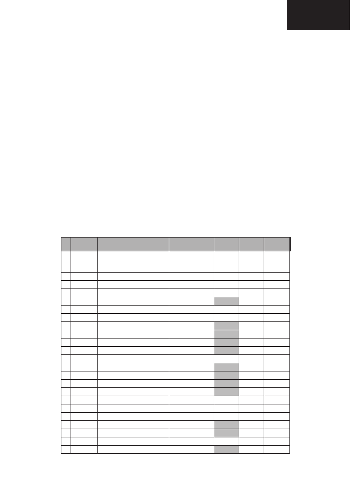
No. OSD Function Range Initial Default FIX/ADJ
25 HTL-VOL Max Hotel Volume 0...63 30 30 FIX
26 HTL-PRG Hotel Program number 0...99 or > 99 for none 255 255 FIX
27 RGB OSD RGB Reference 0...15 15 0 FIX
28 SEARCH-SYS Sound system for auto turning 0(L-BG),1(BG),2(I),3(DK) 1 0 FIX
29 CUT-R Black Level off-set R [BLR] 0...63 0 0 FIX
30 CUT-G Black Level off-set G [BLB] 0...63 0 10 FIX
31 CDL Cathode Drive Level [CL] 0...15 0 5 FIX
32 DL-PT Y-Delay time for PAL (TV) [YD] 0...15 12 4 FIX
33 DL-ST Y-Delay time for SECAM (TV) [YD] 0...15 15 8 FIX
34 DL-4T Y-Delay time for N443 (TV) [YD] 0...15 12 8 FIX
35 COL-OP COLOUR OFFSET (PAL) 0...15 8 8 FIX
36 COL-OS COLOUR OFFSET(SECAM) 0...15 8 8 FIX
37 COL-O4 COLOUR OFFSET (NTSC443) 0...15 4 4 FIX
38 SHP-OP SHARPNESSOFFSET(PAL) 0...15 8 8 FIX
39 SHP-OS SHARPNESSOFFSET(SECAM) 0...15 4 4 FIX
40 SHP-O4 SHARPNESS OFFSET(NTSC443) 0...15 8 8 FIX
41 SC-VOL SCART volume 0..255 115 115 FIX
42 PRE-SC Prescaler SCART input 0..127 25 25 FIX
43 PRE-FM Prescaler FM/AM 0..127 72 72 FIX
44 PRE-NICAM Prescaler SCART input 0..127 0 0 FIX
45 AVC-DKY AVC Decay 0...3 data(1.2.4.8.) 2 2 FIX
46 AC-OFF-TIM Time to set the AC-OFF 0..15 0 0 FIX
timer is in steps of 10minutes
47 DISP Language or symbols 0(symboles), 0 2 FIX
1(English),
2(French)
48 TXT-EUR Teletext pan-European language 0 (teletext pan-european language) 0 0 FIX
1 (second language;cyrillic)
2(third language;Greek)
49 BKS Black Stretch 0 (disable) or 1 (enable) 1 1 FIX
50 AVC Automatic Volume Control(AVL) 0 (disable) or 1 (enable) 0 1 FIX
51 FFI Fast Filter IF-PLL 0 (disable) or 1 (enable) 0 0 FIX
52 ACL Auto Colour Limit 0 (disable) or 1 (enable) 0 1 FIX
53 S-L Sound system L 0 (disable) or 1 (enable) 0 1 FIX
54 S-DK Sound system DK 0 (disable) or 1 (enable) 1 0 FIX
55 S-I Sound system I 0 (disable) or 1 (enable) 1 0 FIX
56 S-BG Sound system BG 0 (disable) or 1 (enable) 1 1 FIX
57 BLUE-BACK Video mute at Ident loss 0 (disable) or 1 (enable) 1 1 FIX
58 VMC Video Mute at program/source Change 0 (disable) or 1 (enable) 1 1 FIX
59 HTL Hotel mode 0 (disable) or 1 (enable) 0 0 FIX
60 BTSC Reduced FM demodulator Gain (for BTSC sig) 0 (disable) or 1 (enable) 0 0 FIX
61 AV Number of external AV sources 0 for 1 AV or 1 for 2 AV 1 0 FIX
62 FMWS FM Window Selection 0 (disable) or 1 (enable) 0 0 FIX
63 SM0 Sound Mute bit 0 0 (disable) or 1 (enable) 1 1 FIX
64 SM1 Sound Mute bit 1 0 (disable) or 1 (enable) 0 0 FIX
65 AGC0 IF AGC speed bit0 0 (disable) or 1 (enable) 1 0 FIX
66 AGC1 IF AGC speed bit1 0 (disable) or 1 (enable) 0 0 FIX
67 FOA-FE Phi 1 time constant for FE(RF) 0 (disable) or 1 (enable) 0 0 FIX
68 FOB-FE Phi 2 time constant for FE(RF) 0 (disable) or 1 (enable) 0 0 FIX
69 FOA-AV Phi 1 time constant for AV 0 (disable) or 1 (enable) 1 1 FIX
70 FOB-AV Phi 2 time constant for AV 0 (disable) or 1 (enable) 1 1 FIX
71 TXT Teletext 0 (disable) or 1 (enable) 0 0 FIX
72 TXT-WE Teletext Western or Eastern characters 0 (westem) or 1 (eastem) 0 0 FIX
73 FSL Forced V-SYNC slicing level 0 (disable) or 1 (enable) 0 0 FIX
74 HP2 Sync of OSD 0 for Ph1 or 1 for Ph2 0 0 FIX
75 CP Charge pump 0 (fast tuning) or 0 0 FIX
1 (moderate speed tuning)
76 NICAM NICAM decoding enabled 0 (disable) or 1 (enable) 0 0 FIX
77 IGR IGR decoding enabled 0 (disable) or 1 (enable) 0 0 FIX
78 AUTO Start auto tuning at POWER-ON 0 (disable) or 1 (enable) 0 0 FIX
79 TXT-TGL Function of TXT key 0 or 1 0 1 FIX
80 EVG Enable Vertical Guard 0 (disable) or 1 (enable) 1 1 FIX