ShenZhen JHC Technology Co. EPI-I707 User manual
1
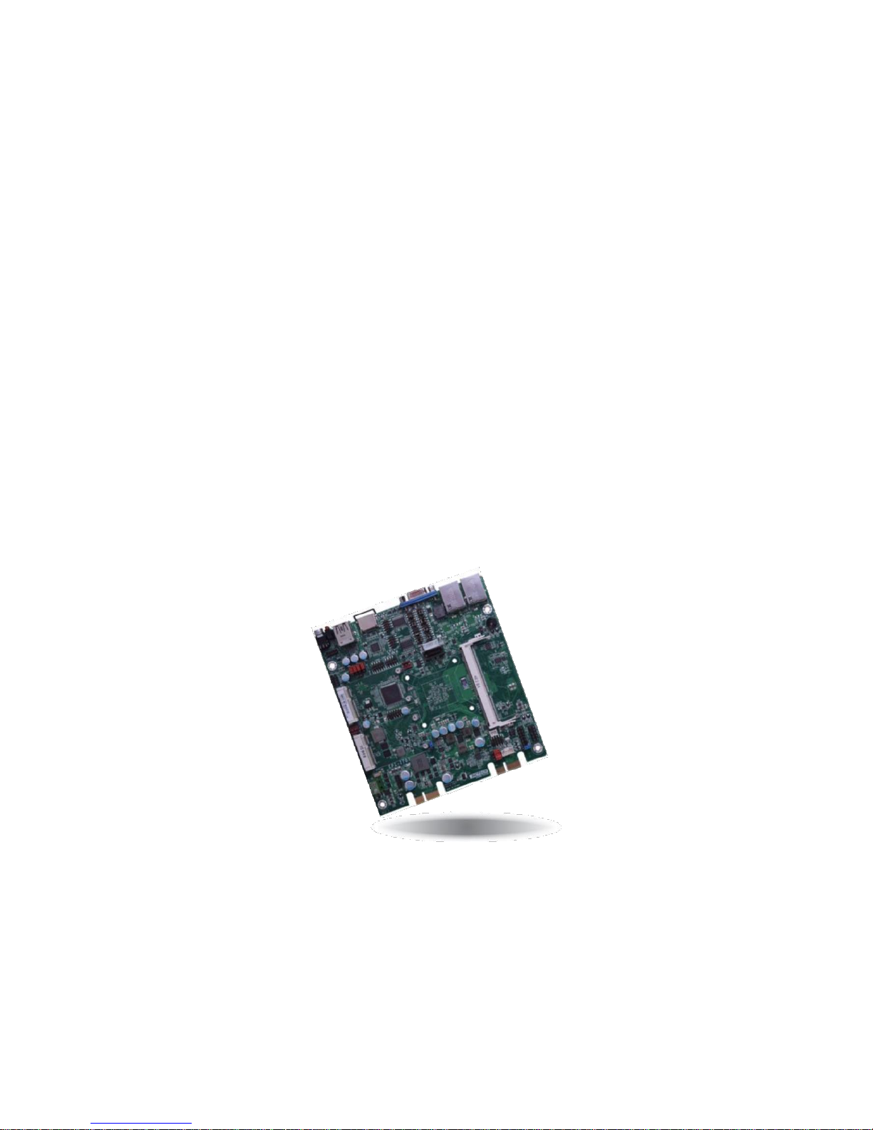
EPI-I707
User’s Manual

I
Copyright
The documentation and the software included with this product are copy- righted 2006 by
ShenZhen JHC Technology Co., Ltd. All rights are reserved. ShenZhen JHC Technology
Co., Ltd. reserves the right to make improvements in the products described in this
manual at any time without notice. No part of this manual may be reproduced, copied,
translated or transmitted in any form or by any means without the prior written
permission of ShenZhen JHC Technology Co., Ltd. Information provided in this manual
is intended to be accurate and reliable. However, ShenZhen JHC Technology Co.,
Ltd.assumes no responsibility for its use, nor for any infringements of the rights of third
parties, which may result from its use.
Acknowledgements
Award is a trademark of Award Software International, Inc.
IBM, PC/AT, PS/2 and VGA are trademarks of International Business Machines
Corporation.
Intel and Pentium are trademarks of Intel Corporation.
Microsoft Windows and MS-DOS are registered trademarks of Microsoft Corp.
RTL is a trademark of Realtek Semi-Conductor Co., Ltd.
All other product names or trademarks are properties of their respective owners.
For more information on this and other JHC products, please visit our websites at:
http://www.jhctech.com.cn

II
Product Warranty (2 years)
JHC warrants to you, the original purchaser, that each of its products will be free from
defects in materials and workmanship for two years from the date of purchase.
This warranty does not apply to any products which have been repaired or altered by
persons other than repair personnel authorized by JHC, or which have been subject to
misuse, abuse, accident or improper installation.
JHC assumes no liability under the terms of this warranty as a consequence of such
events.
Because of JHC.s high quality-control standards and rigorous testing,most of our
customers never need to use our repair service. If an JHC product is defective, it will be
repaired or replaced at no charge during the warranty period. For out-of-warranty repairs,
you will be billed according to the cost of replacement materials, service time and freight.
Please consult your dealer for more details.
If you think you have a defective product, follow these steps:
1. Collect all the information about the problem encountered. (For example, CPU
speed, JHC products used, other hardware and software used, etc.) Note anything
abnormal and list any onscreen messages you get when the problem occurs.
2. Call your dealer and describe the problem. Please have your manual, product, and
any helpful information readily available.
3. If your product is diagnosed as defective, obtain an RMA (return merchandise
authorization) number from your dealer. This allows us to process your return more
quickly.
4. Carefully pack the defective product, a fully-completed Repair and Replacement
Order Card and a photocopy proof of purchase date (such as your sales receipt) in a
shippable container. A product returned without proof of the purchase date is not
eligible for warranty service.
5. Write the RMA number visibly on the outside of the package and ship it prepaid to
your dealer.

III
Declaration of Conformity
CE
This product has passed the CE test for environmental specifications
when shielded cables are used for external wiring. We recommend the use
of shielded cables. This kind of cable is available from JHC. Please
contact your local supplier for ordering information. Test conditions for
passing included the equipment being operated within an industrial enclosure.
In order to protect the product from being damaged by ESD (Electrostatic
Discharge) and EMI leakage, we strongly recommend the use of
CE-compliant industrial enclosure products.
FCC Class A
Note: This equipment has been tested and found to comply with the limits for a Class A
digital device, pursuant to part 15 of the FCC Rules. These limits are designed to provide
reasonable protection against harmful interference when the equipment is operated in a
commercial environment This equipment generates, uses, and can radiate radio frequency
energy and, if not installed and used in accordance with the instruction manual, may
cause harmful interference to radio communications. Operation of this equipment in a
residential area is likely to cause harmful interference in which case the user will be
required to correct the interference at his own expense.
Technical Support and Assistance
Step 1. Visit the JHC web site at www.jhctech.com.cn
where you can find the latest information about the product.
Step 2. Contact your distributor, sales representative, or JHC’s customer service center
for technical support if you need additional assistance. Please have the following
information ready before you call:
- Product name and serial number
- Description of your peripheral attachments
- Description of your software (operating system, version,application software,
etc.)
- A complete description of the problem
- The exact wording of any error messages

A
Contents
General Information............................................................................................................ 1
1.1 Introduction ....................................................................................................... 2
1.2 Features ............................................................................................................. 3
1.3 Specifications .................................................................................................... 3
1.3.1 General.................................................................................................... 3
1.3.2 Display.................................................................................................... 4
1.3.3 Ethernet...................................................................................................... 4
1.3.4 Power Consumption................................................................................... 4
1.3.5 Power Requirement.................................................................................... 4
1.4 Environmental Specifications............................................................................... 4
1.5 Mechanical Specifications.................................................................................... 5
Hardware Installation.......................................................................................................... 7
2.1 Introduction........................................................................................................... 8
2.2 Jumpers and connectors........................................................................................ 8
2.2.1 Setting Jumpers.......................................................................................... 8
2.3 Jumper Location.................................................................................................... 8
2.3.1 JP2: Clear CMOS..................................................................................... 10
2.3.2 JP6/7/8/9 USB Power Select.................................................................... 11
2.3.3 COM 1/COM 2 RS232/422/485 Select ................................................... 12
2.3.4 COM 1/COM 4 RS232/Power Select...................................................... 14
2.3.5 Digital I/O Power Select.......................................................................... 14
2.3.6 Digital I/O Output State........................................................................... 15
2.3.7 Auto Power-on Select .............................................................................. 16
2.4 Connectors .......................................................................................................... 16
2.4.1 DIO Connectors....................................................................................... 16
2.4.2 Front Panel Connector ............................................................................. 17
2.4.3 Front Audio Connector ............................................................................ 19
2.4.4 mini PCI-E Connectors............................................................................ 19
2.4.5 SIM Card.................................................................................................. 20
2.4.6 Cooling Fan Connectors .......................................................................... 21
2.4.7 SMBus Connector.................................................................................... 21
2.4.8 DC-IN 12~24V ........................................................................................ 22
2.5 I/O indication...................................................................................................... 23
BIOS Setup ....................................................................................................................... 25
3.1 Main.................................................................................................................... 27
3.2 Advanced............................................................................................................. 28
3.2.1 Boot Configuration .................................................................................. 28
3.2.2 PCI Express Configuration...................................................................... 29
3.2.3 Miscellaneous Configuration................................................................... 30
3.3 Security ............................................................................................................... 31
3.3.1 Set Supervisor Password.......................................................................... 31
3.4 Power .................................................................................................................. 32
3.4.1 Advanced CPU Control............................................................................ 32

B
3.5 Boot..................................................................................................................... 33
3.5.1 Legacy...................................................................................................... 34
3.6 Exit...................................................................................................................... 36
Driver Installation............................................................................................................. 37
4.1 Follow the sequence below to install the drivers:............................................... 38
4.2 Installation: ......................................................................................................... 38
Watchdog Sample Code.................................................................................................... 39

1
General Information
CHAPTER
1

2
1.1 Introduction
Processor
• Intel® Celeron® processorN2807:
Intel® Celeron® N2807, Dual Core, 1M Cache, up to 2.16GHz, 4.3W
• BGA 1170 packaging technology
• 22nm process technology
Super I/O Address
• NCT6106/4Eh
System Memory
• One 204-pin DDR3L SODIMM socket
- up to 4GB system memory
- single channel memory interface
• Supports DDR3L 1333MHz
• DRAM device technologies: 1Gb, 2Gb and 4Gb DDR3L DRAM technologies are supported for x8 and
x16 devices, unbuffered, non-ECC
Expansion
Interfaces
• 2 PCIe x1 slots
- One slot supports x1 signal
- One slot provides power supplement only.
• 1 SIM card socket
• 2 Mini PCIe slots
- Supports USB and PCIe signals
- Supports mSATA
- Supports half size or full size Mini PCIe card
Graphics
• Intel® HD Graphics
• Display ports: HDMI and VGA
• VGA: resolution up to 1920x1600 @60Hz
• HDMI: resolution up to 1080p @60Hz
• Supports hardware acceleration for DirectX 11, OCL 1.2, OGL 3.2, H.264, MPEG2, MVC, VC-1,
WMV9 and VP8
Audio
• Realtek ALC888 High Definition Audio
LAN
• 2 Intel® WGI210IT PCI Express Gigabit Ethernet controllers
• Integrated 10/100/1000 transceiver
• Fully compliant with IEEE 802.3, IEEE 802.3u, IEEE 802.3ab
Serial ATA
• 1 SATA 2.0 port with data transfer rate up to 3Gb/s
• Integrated Advanced Host Controller Interface (AHCI) controller
Trusted Platform Module
- TPM (optional)
• Provides a Trusted PC for secure transactions
• Provides software license protection, enforcement and password protection
WatchDog Timer
• Watchdog timeout programmable via software from 1 to 255 seconds
Rear Panel I/O Ports
• 2 RJ45 LAN ports
• 1 HDMI port
• 1 VGA port
• 1 USB 2.0 port
• 1 USB 3.0 port
• 1 HDD LED
• 1 power LED
• 1 power button
I/O Connectors
• 3 connectors for 4 external USB 2.0 ports
• 4 connectors for 4 external serial ports (2.0mm pitch)
- 2 RS232/RS422/485 (RS232 and/or power)
- 2 RS232
• 1 12~24V DC-in connector
• 1 8-bit DIO connector
• 1 DIO power connector
• 1 front audio connector for line-out and mic-in jacks
• 1 LPC connector
• 1 Serial ATA connector
• 1 Serial ATA power connector
• 1 front panel connector
• 1 chassis intrusion connector
• 2 fan connectors
BIOS
• Insyde BIOS
- 64Mbit SPI BIOS

3
Energy Efficient
Design
• Supports ErP Lot6 power saving
• Supports ACPI
• System Power Management
• Wake-On-Events include:
- Wake-On-USB KB/Mouse
- Wake-On-LAN
- RTC timer to power-on the system
• AC power failure recovery
Damage Free
Intelligence
• Monitors CPU/system temperature and overheat alarm
• Monitors VCORE/12V/5V voltages and failure alarm
• Monitors CPU/system fan speed and failure alarm
• Read back capability that displays temperature, voltage and fan speed
Power
Consumption
• 10.51W——Boot Up
• 10.32W——Idle
• 10.96W——Max load
• 1.54W——S3
• 1.50W——S5
OS Support
• Windows 7
• Linux Fedora Ubuntu
Temperature
• Operating: 0oC to 60oC
• Storage: -20oC to 85oC
Humidity
• 5% to 95%
Dimensions
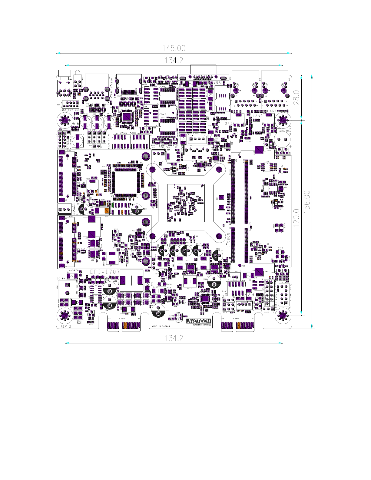
• 156mm x 145mm
1.2 Features
Key features
1、Intel® Celeron® N2807 (Intel Bay Trail-M) 1.58GHz up to 2.16GHz,TDP 4.5Watt;
2、1xDDR3L-1333 SODIMM ,max 4GB;
3、1xminipcie with SIM card support 3G;
4、DC 12V~24V Wide voltage input;
5、VGA&HDMI display;
6、4COM/8DIO;
7、2×Intel I210IT Gigabit Ethernet ;
1.3 Specifications
1.3.1 General
CPU: Intel® Celeron® N2807 (Intel Bay Trail-M) 1.58GHz up to 2.16GHz
BIOS: Insyde BIOS
System Memory: Up to 4G DDR3L 1333GHz SODIMM
Watchdog Timer: 255-level interval timer, setup by software

4
Serial Ports:
–2x RS-232, 2 x RS-232/422/485
DIO:
–8 bit DIO
USB:
–4 x USB 2.0 compliant Ports ,1xUSB3.0 compliant port.
Expansion Interface: Support up to 1 x full size Mini-PCIe
Storage:
–Supports 1 xmSATA
–SATA: Support 4 x 3.5” SATAIII HDD
1.3.2 Display
Chipset: Intel HD Graphics; GPU Frequency: 313 MHz
Display Memory: Shared system memery up to 224MB SDRAM
VGA Resolution: Supports up to 2560 x 1600
1.3.3 Ethernet
Chipset: 2xIntel WGI210IT Gigabit Ethernet
Speed: 10/100/1000 Mbps
Interface: Up to 2 x RJ45
1.3.4 Power Consumption
Input Voltage: DC 12~24V
Power Adapter: AC to DC 19 V/6.32 A, 120 W
1.3.5 Power Requirement
System power:
–Minimum power input: DC 19 V 1 A
1.4 Environmental Specifications
Operating temperature: 0 ~ 60°C (With extended temperature mSATA devices) & 0
~ 50°C (With standard temperature mSATA&HDD devices)
Relative humidity: 95% @ 40°C (non-condensing)

5
Storage temperature: -40 ~ 85°C (-40 ~ 185°F)
Vibration loading during operation:
–With SSD/mSATA: 3 Grms, IEC 60068-2-64, random, 5 ~ 500 Hz, 1 hr/axis
Shock during operation:
–With SSD/mSATA: 30 G, IEC 60068-2-64, half sine, 11 ms duration
EMC: CE, FCC Class A
1.5 Mechanical Specifications
EPI-I707 Dimensions:
6

7
Hardware Installation
CHAPTER
2

8
2.1 Introduction
The following sections show the internal jumper settings and the external connectors and
pin assignments for applications.
2.2 Jumpers and connectors
2.2.1 Setting Jumpers
You can configure your EPI-I707 to match the needs of your application by setting the
jumpers. A jumper is the simplest kind of electrical switch. It consists of two metal pins
and a small metal clip (often protected by a plastic cover) that slides over the pins to
connect them. To —close“ a jumper, you connect the pins with the clip. To —open“ a
jumper you remove the clip. Sometimes a jumper will have three pins, labeled 1, 2, and 3.
In this case, you would connect either pins 1 and 2 or pins 2 and 3.
The jumper settings are schematically depicted in this manual as follows:
A pair of needle-nose pliers may be helpful when working with jumpers. If you have any
doubts about the best hardware configuration for your application, contact your local
distributor or sales representative before you make any changes.
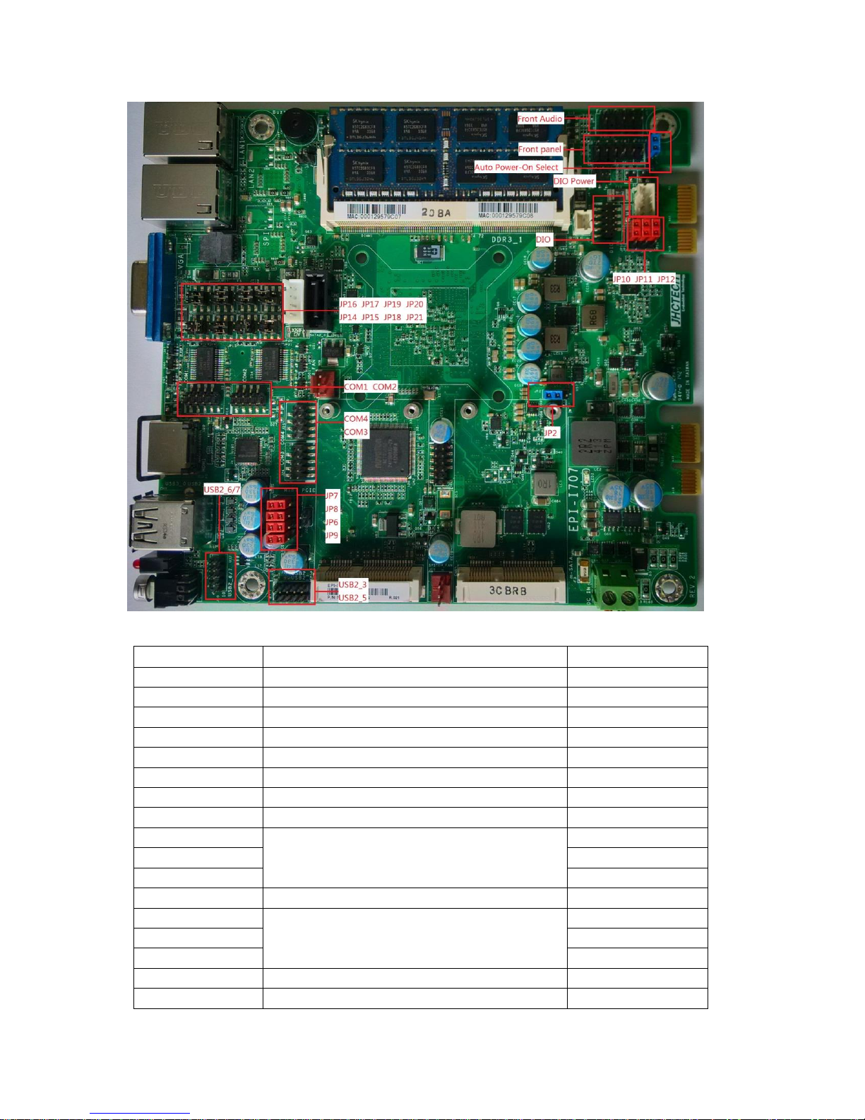
2.3 Jumper Location
The EPI-I707 Embedded Box Computer has a number of jumpers inside the chassis that
allows you to configure your system to suit your application. The table below lists the
functions of the various jumpers. The table below shows the function of each of the
board's jumpers:
9
Jumpers
Jumper
Name
Description
JP2
CMOS RAM Clear Function Setting
3-Pin Block
JP6
USB power select
3-Pin Block
JP7
USB power select
3-Pin Block
JP8
USB power select
3-Pin Block
JP9
USB power select
3-Pin Block
JP10
DIO power Select
3-Pin Block
JP11
DIO 4-7 output state
3-Pin Block
JP12
DIO 0-3 output state
3-Pin Block
JP14
COM1 RS232/422/485 select
6-Pin Block
JP15
6-Pin Block
JP17
6-Pin Block
JP16
COM1 RS232/power select
3-pin Block
JP18
COM2 RS232/422/485 select
6-pin Block
JP19
6-pin Block
JP21
6-pin Block
JP22
Auto Power-On Select
3-pin Block
JP20
COM4 RS232/power select
6-pin Block

10
Headers
Header
Name
Description
Front Audio
Front panel audio header
9-pin block
Front Panel
Front Panel header
11-pin block
USB2_3
USB2_5
USB header
5-pin block
USB2_6/7
USB header
9-pin block
COM1/COM2/
COM3/COM4
Serial port headers
9-pin block
DIO Power
DIO Power header
4-Pin block
2.3.1 JP2: Clear CMOS
If you encounter the following,
a) CMOS data becomes corrupted.
b) You forgot the supervisor or user password.
you can reconfigure the system with the default values stored in the ROM BIOS. To load
the default values stored in the ROM BIOS, please follow the steps below.
1. Power-off the system and unplug the power cord.
2. Set JP2 pins 2 and 3 to On. Wait for a few seconds and set JP2 back to its default
setting, pins 1 and 2 On.
3. Now plug the power cord and power-on the system.

11
2.3.2 JP6/7/8/9 USB Power Select
JP6, JP7, JP8 and JP9 are used to select the power of the USB ports. Selecting
+5V_standby will allow you to use a USB device to wake up the system.
Important:
If you are using the Wake-On-USB Keyboard/Mouse function for 2 USB ports,
the+5V_standby power source of your power supply must support ≥1.5A. For 3 or
moreUSB ports, the +5V_standby power source of your power supply must
support ≥2A.

12
2.3.3 COM 1/COM 2 RS232/422/485 Select
These jumpers allow you to configure the Serial COM ports to RS232, RS422 (Full
Duplex) or RS485. JP14, JP15 and JP17 are used to configure the Serial COM port 1.
JP18, JP19 and JP21 are used to configure the Serial COM port 2. The pin functions of
Serial COM ports 1 and 2 will vary according to these jumpers’ setting.
Note:
When COM 1 RS232/422/485 is selected, JP15 and JP17 must be set in accordance to JP14. And
when COM 2 RS232/422/485 is selected, JP19 and JP21 must be set in accordante to JP18.

13
14
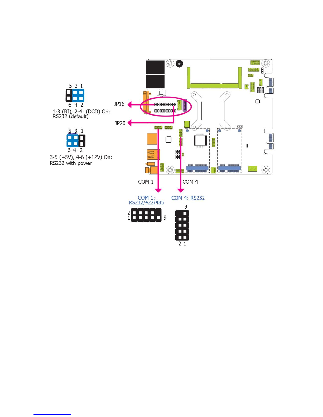
2.3.4 COM 1/COM 4 RS232/Power Select
JP16 (for COM 1) and JP20 (for COM 4) are used to configure the Serial COM ports to
pure RS232 or RS232 with power.
2.3.5 Digital I/O Power Select
Table of contents


