manuals.online logo
Brands
  1. Home
  2. •
  3. Brands
  4. •
  5. Sherwood
  6. •
  7. Amplifier
  8. •
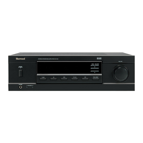
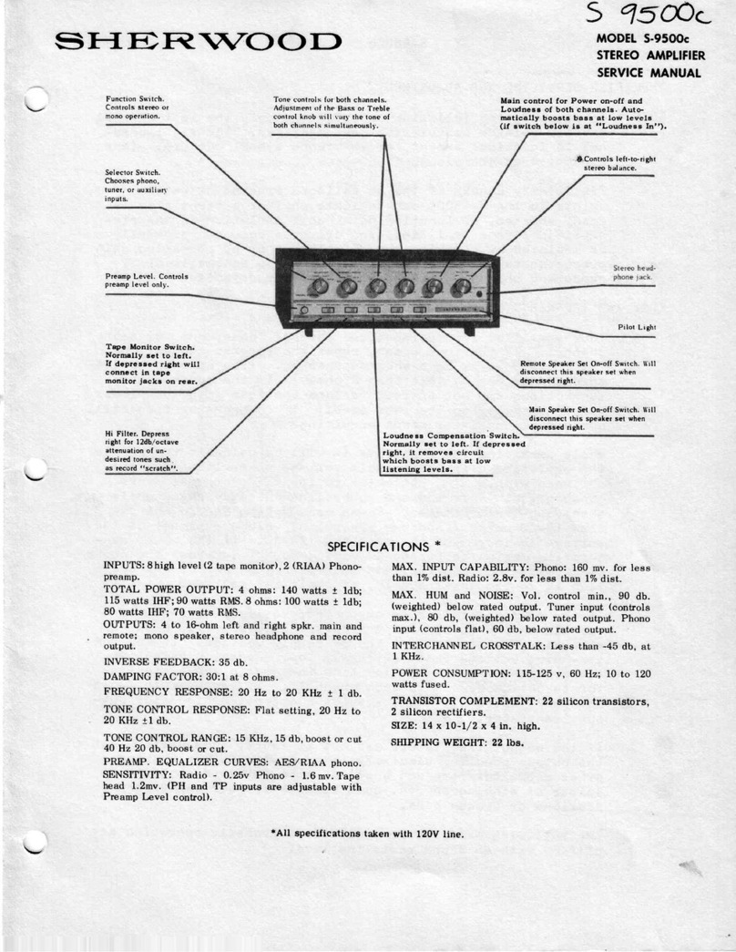
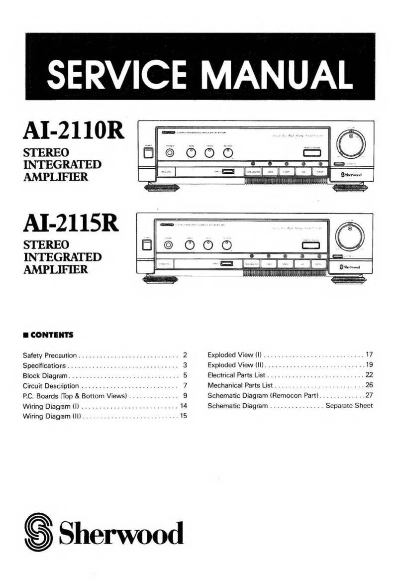
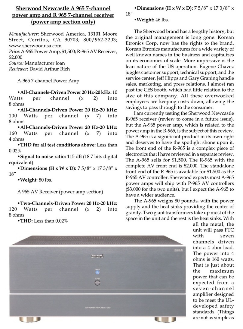
  9. Sherwood S-9500 User manual

Sherwood S-9500 User manual

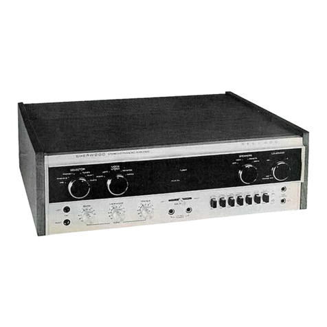
5-9500
50 WATT ALt SILICOI\
II\TEGRATED
TRAI\SISTORAMPTIFIER
Funclion Switch
conlrols slereoor
mono
operolion.
5elects
left
ond
right
input
chon-
nel
simultoneously.
Phono
Goin.
Contr
preomp
level
only.
TopeMonitor
Switch.
Normolly
set
to left,
will
connectintope
monitor
iock
onreor
if switchedtoright.
Tone controls for both chonnels.
Adjustmentof the Boss or Treble
conlrol knobwill vory the tone of
both
chonnels
simultoneously.
'Ff
i.-fTtttil:''*Sfi
itch'
ro
right for l2dbloctove
otlenuotion
of un-
desired lones such
os record "scrolcht'.
Moin controlfor Power on-off ond
Loudnessof both chonnels. Auto-
moticolly boosts boss ot low.levels
(if swirch below
ol "Loudness In").
Controls
left-to-right
stereobolonce
Pilot
Lighr
Speoker
"on-off" switch.
Normolly
set to left, will
disconnecl speokers when
switched to right.
Loudness Compensotion
Switch.
Normolly set to left, will remove
circuit which boostsboss ot low
seftings of Loudness control if
switched to right.
DESIGN
-CENTER
SPECIFICATIONS*
INPU
TS:
6 high
level
(2tope
monitor),
2(RIAA)
Phono-preomp.,
2
(NAB)
topeheod
preomp.
POWER
OUTPUT:
Stereo-Eoch
chonnel
Zs
wottsmusic
power
(20
wottscontinuous)
ot1.5%
llt distortion
(60c:7kc/4:1).
0UTPUTS:
4
to 16-ohm
left
ond
right
spkr.;
stereo
heodphone
ondrecord
output.
INVERSE
FEEDBACK:
45db.
DAMPING
FACTOR:
l5:l ot
8
ohms.
FREQUENCY
RESPONSE:
(20w)
20cps
to 20kc
tl db.
TONE
CONTROL
RESPONSE:
Flot
setting,
20
cpsto20
kc
tl db.
TONE
CONTROL
RANGE:
l5 kc,
I5db.
boost
orcut.
40
cps.
l6db.
boost
orcut.
MAX.
INPUT
CAPABILITY:
Phono:
35mv.
forless
thon
.1%dist.
Rodio:
2.8v.
for
lessthon
.l%
dist.
*Att specificati,ons
with 120V
AC line.
PREAMP.EQUALIZER
CURVES:
AES/RIAA
phono
ondNAB
tope.
SENSITIVITY:
Rodio-0.
25v.
Phono-l
.8mv.
Tope
heod-,8mv.
(PH ondTP inputsore
odiustoble
with
Phono
Goincontrol).
MAX.
HUM
ond
NOISE:
Vol. control
min.,
90db.
(weighted)
below
roted
output.
Tunerinput
(controls
moxi-
Iym), B0db.
(weighted)
below
rored
ourpur.
Phono
input (contuols
flot), 70db.
bel'ow
roted
output.
INTERCH
ANN
EL
CROSSTALK:
Better
thon
- 45db
ot Ikc.
POWER
CONSUMPTION:
ll5-125v,
60
cps;
l0 to
100
wottsfused.
TRANSI
STOR
COMPL
EMENT:
20
siI
icon
tron
sistors
2si
I
icon
rectif
iers
SIZE:
ll x l2Yzx
4in.
hish.
SHIPPING
WEIGHT:
20
lbs.
INFORMATIO
s-9500
sERVlclNG
VOTTAGE
CHECKS
Preliminary checks of tlte D.C. voltages
present at various points in the 5-9500 can
i"ove usefulinlocatingdefectivecomponenttil
They are inconclusive,
however,
in determin-
ing if transistors are operating properly in
all aspects. They can only indicate whether
the transistor is open,
shortedor fgnctioning,
not how well the transistor is functioning.
IN GENERAL:
Correct voltages indicate a functioning
transistor.
The same voltage at the colleetor 4nd
emitter indicates ashortedtransistor.
FUll supply voltage on the collector and
no voltage onthe emitter indicates an
open
transistor.
OUTPUT
TRANSISTOR
BIAS
Of all the specifications which require eheck-
ing to ascertain eorrect performance of the
S-9500,proper outputtransistor operationis
the most important and critieal. Adjustment
of the output transistor bias is necessary if
output transistors are replaced*, or the
amplifier exhibits one or more of thefollow-
ing symptoms:
1. Overheating of the output transistors
under normal operating conditions.
2. Excessive low level Intermodulation
Distortion more than 0.t% at 1.5
volts across I ohms(0.28
wattoutput).
Adjustment of output transistor bias should
then proceed as follows:
FI
G.
I
* It is extremely important that the mica insulating rih"", usedto separatethe output
transistors from their heat-s
beunbrokenandinstatled properly, with silicon grease liberally appliedto all surfaces in contactwith eachother. A
make certain the emitter and bas-e
pins of the output transistors do not contact anypart of the heat-sinks. (See
p
list, Page6A.
)
NOTE: The fuses located on each channels driver board protect the output transistors against very heavy transients or
short circuits. They should be replaced with identlcal fuses when blown
1.
2.
Turn amplifier off.
Set balance
pots (R52
and
R152)
to mech-
anical center and bias pots (R60 and
Rl 60)ftrlly counter-
cloclwise.
Conneet D.C. voltmeter of at least SVo
known accuracy to the hot side of the
appropriate channel'soutputcapacitor.
Turn amp. on and adjust balance pot
(R52 or R152) so that exaetly t/2 B+
voltage is onthe output capacitor.
Turn volume eontrol to maximum. Con-
nect anIntermodulation Distortion analyz-
er to the amplifier alx. input and adjust
the analyzer output for anamplifier output
of 1.5Vacross 8 ohms. (Because
the out-
put stageshavebeenset into healy class
3'B." oleration by the "pre-setting" in
Step2, L elass ' eB" notchinthedistortion
waveform will be obvious.) Adjust the
bias pot (R60or R160)for rninimum dis-
tortion as shownin Fig. 1.
IMPORTANT: Misadjustment Of the
bias pot cancauseheavyclass 3'A,,
oper-
ation of the output transistors, causing
them to overheat.
The following performance indicates 4
properly operating output stage:
Typically O.LVo
I.M. distortion at1.5V
across 8 0hms.
Tlpically LVo
I.M. distortion at 10V
across 8 0hms.
20 watts of power per channel,before
clipping; both channels operating.
3.
4.
5.
6.
PULL
OUT
FOR
CHASSIS
LAYOUT 9A
s-9500
cHASSlSLAYOUTS
UPPERQ9 UPPER QI9
PRE-AMP
SELECTOR
FUI{GTION
BASS TREBLE
VOLUME
BALANCE
(ALL
P.CBOARDS
VIEWED
FnomrRANslsroR
slDE)
TI
B922T2
fidfi
E=,..,fi
R52 | Rl52I
cH-l cH-z
,-,,-,[{
EEL-R6O Gt82 rFGE-1in-
-
,1 tl^s
9'
o7-or?
OIJTPT'I
!rLrl|cE
o
oc-or5
oB""
oa-ort
Qoroz Ooz
PRE-AMP
BOARD
Ooror -O ot
TO]IIE-AMPLIFIER
BOARD
LE1/EL
@
p
o
,,r,
*lEl
trll
roof lrl
o
LEFT-
I
.ttrl ^
o
Js""@_o
RICHT-2
o*@"n@_
'*bo
od'
o oor,
iL"lOg
OO
clt lcll 2 CHlcHt
BACK
PANEL
VIEW
TRANSISTOR PART
NO. COST
PERUNIT LIST
Low Signol-No Dot
Low Signql-Yellow
Dot
Low Signol-Org.
Dof
Pre-Driver
PNP Driver
NPN Driver
Output
2N3391
A
2N3392
2N3393
2rn416
sL3l0l
NX7
4995
s354
1.49
r.3l
1.26
3.69
6.08
3.60
6.7
5
s-9500
PARTSUST
you wilt notethot oll tronsistorsused
in the5-9500
orecolor-coded
with o dotor mork
of somecolor
promine
locqted
on the top of their cose.(Some
tronsistors
hove
no mork,but this olso is identificotion.)
When
orde
replocement
tronsistors,
it is imperotive
thot you indicote
not
only its port
no., butthe color
dot
on thetronsi
body:
red,
yeltow,none,
etc. This is porticulorly
importont
whenreplocing
output
tronsistors.
DESCRIPTION PART
NO. COST
PER
UNIT
LIST
Knob (Ors. Dot)
Knob(PhonoLevcl)
Boss Control
Trcble Con?rol
Volumc Control
Boloncc C-ontrol
Phono Levcl Control
P-CPot.
5000
P-CPot.l50K
Germonium
Diodc
B+ Rcct.
Output Trons. Skt.
Driver Trqrs. Skt.
HcodphoneJock
Fusc Posl
Function Switch
Sclcctor Switch
Slidc Swirch
Powcr Trqrsformcr
A450Ll0-4
A46085-2
A670T5
A670T6
A67lTl
MTOTI
A670T3
M75TI
M75T2
A69lM3
M92T3
A790T3
A790'r4
A795Ll
A796Xl
A860Ks-l
A860K36
A864T4
Bg?2T2-2
.54
.15
2.52
2.52
3.42
.81
r.80
.90
.90
.21
l.l3
.15
.25
1.04
.75
r.62
4.
l9
.59
10.6s
.9
.63
.63
.63
.63
.53
.53
l.3l
1.80
.63
3.38
3.74
.09
3.33
3.83
2.48
.14
.14
.50
Bl20x3
Bl20xr
Bl20x4
Bl20x6
Bl20xl2
Bl20xl4
Bl20x24
Bl20x3l
Bl20x29
Bl20x5
At20T7
Al20T8
A02tF2
A03lT7
A03lT5
A03lT6
312001
312002
446,0L7-4
.5
pfQ
50V
lFf0lsv
5pf05V
5pf@20v
Dpfosv
20
pf
0
sov
100
pf0 3v
500pf 0 25v
500pf 0 40v
lpf0lsv
ls00
Ff03sv
l$0 pf065v
Mico
lnsulotor
Phono
P-C
Bd.
Pre-Amp
P-C
Bd.
Drivcr
P'CBd.
Fusa,
I Anp.
Fusc,
2Anp.
Knob
(Bluc
Dot)
5-9500
PERFORMANCE
GRAPHS
FICEUENCY IX CYCLET ?CT SECC'ND
ttteulrcv lta cYcr.:s ?:i sccoilo
20 50 IOO 2OO 5OO lr 7. tr lor 2Or
IJI|J 0a
-6a
\-t24
\
\-?,'dA
LOUDNCSS CONTiOL
CHAiACTERISTICS
-3Odb
4&
?lOWEi OUT?UI
VS DlSTOnTlOlr
l^r to r^''
lacn cxlxxsi
HAiroNrc DrsTonTtox
llustc Powci
tiTCitrtoDullTtoN
DIS'ORTION
t&E,r/78 rftl \/
\6t
. FREEUENCY IN CYCLES PCN SECOND
20 50 tOO 200 5OO lK 21 5r lox 2Or
+Xl
+lO
o
ul
co
(,
u
o
-t0
-20
TONE CONTNOL ANO
FILTER CHARACTERISTTCS
FREGIUENCY
IN CYCLESPERSECOND
20 50 loo 2oo 500 lK 2x 5r lox 20K 50r looK
o
d-5
o
a
ur -lO
o_t5
lll
AUDIO RANGE
rll
7I
IIIE ,x\
roKc
gouAtE
wAvE
\
\
\
\
hls iJF
POWERAMPLIFIER
RESPONSE
7B
I
o.22
_lIL
l=
I cr:
, | .ooez
R28A 250x
TREBLE
NORX
(
s
FUNCTION
Sz
'fE\, (STEREO)
2.xoRil (STEREO)
1 CH.| (ftloilo)
4.
CH.2
(MONOI
s.cH
ra2(roNol
il2l
!.9X
tlv
lttl
3 l6Mv
0ass
BOOST
R24A tr
R288 ?30x
TREBLE
cur e?r
(azen 1c.22 2r{3392
1.t v
eN3Cr6
2N339rA
2N339
2
2N3393
l'F-d
r1llh
./ l.
\"
ltoRI(
SHERWOODS-95OO
50 WATTSTEREO
AMPLIFIER
SER,AINo. 1400001
AND UP
Rta|
AMPLIFIER
| ';;" c40 2.2x
4tK sWV
2O1tt
DRIVER
lro-s
rre -
OUTPUT
BALR52
R50
?2Ot<
tav
c4r
O.5
1f
50tYv
f ---, --- - ;- -;,tv;-.--]
OUTPUT
BAL.
Rl52
t50x
,EV
O.5rtf
50wv
t-l
IA
R27
w
39X c4?
47
R42
rox
tet o.7v
c32 J r----J
l, to.ort R43
ef?
t5
2w
I,
3l
or5 .ol
HI FILTER
R35A
50x
outo
s54
IN
3.9t(
NORM }II FILTER
s4a
t|,r O.7V
d3?
.ol
R37
56X
Rr37
56K
RIGHT
(2I t
STE
R€O
HEAOP|lOr€S
ct12
a7
Rr42
lot(
3$/?avv
Ql4 ---
?N5393
-l c14t
R358
50K
os58
IN
Rr43
2,2
2N3393
o.t5v
4f,X ZO,,r
O.7Y
5WV
lIORM
s-9500
i'J AMPLIFIER
OOI
AND UP
NOTE:
ALL RESISTORS
ARE I/2WATT,'I096
W
SPECIFIED. ALL FRACTIONAL-
@
OTHER CAPACITORS
EXCEPT
ELECTROLYTICS ARE lN pf.
"'"$$q*,

Other Sherwood Amplifier manuals

Sherwood AVP-9080 User manual

Sherwood

Sherwood AVP-9080 User manual

Sherwood AX-5103 Reference manual

Sherwood

Sherwood AX-5103 Reference manual

Sherwood Newcastle P-965 User manual

Sherwood

Sherwood Newcastle P-965 User manual

Sherwood Newcastle A-965 User manual

Sherwood

Sherwood Newcastle A-965 User manual

Sherwood AI-2110R User manual

Sherwood

Sherwood AI-2110R User manual

Sherwood Newcastle A-965 Owner's manual

Sherwood

Sherwood Newcastle A-965 Owner's manual

Sherwood Newcastle R-965 User manual

Sherwood

Sherwood Newcastle R-965 User manual

Sherwood Newcastle P-965 User manual

Sherwood

Sherwood Newcastle P-965 User manual

Sherwood AX-3030R User manual

Sherwood

Sherwood AX-3030R User manual

Sherwood S-9500c User manual

Sherwood

Sherwood S-9500c User manual

Sherwood S-9500B User manual

Sherwood

Sherwood S-9500B User manual

Sherwood AX-5505 User manual

Sherwood

Sherwood AX-5505 User manual

Sherwood XA-1141 User manual

Sherwood

Sherwood XA-1141 User manual

Sherwood XA-5450 User manual

Sherwood

Sherwood XA-5450 User manual

Sherwood AX-7R User manual

Sherwood

Sherwood AX-7R User manual

Sherwood Newcastle A-965 User manual

Sherwood

Sherwood Newcastle A-965 User manual

Sherwood SEL-400 User manual

Sherwood

Sherwood SEL-400 User manual

Sherwood AX-5103 User manual

Sherwood

Sherwood AX-5103 User manual

Sherwood AX-4103 User manual

Sherwood

Sherwood AX-4103 User manual

Sherwood am-9080 User manual

Sherwood

Sherwood am-9080 User manual

Sherwood S-1000 Manual

Sherwood

Sherwood S-1000 Manual

Sherwood AX-50 User manual

Sherwood

Sherwood AX-50 User manual

Sherwood S-9400 User manual

Sherwood

Sherwood S-9400 User manual

Sherwood ES-5030R User manual

Sherwood

Sherwood ES-5030R User manual

Popular Amplifier manuals by other brands

Nembrini Audio MP1 PRO manual

Nembrini Audio

Nembrini Audio MP1 PRO manual

YASKAWA SGDS Sigma III Series user manual

YASKAWA

YASKAWA SGDS Sigma III Series user manual

THORLABS PDFA100 operating manual

THORLABS

THORLABS PDFA100 operating manual

Chord ULTIMA PRE user manual

Chord

Chord ULTIMA PRE user manual

Yamaha XDA-AMP5400RK owner's manual

Yamaha

Yamaha XDA-AMP5400RK owner's manual

Rockbox Matador manual

Rockbox

Rockbox Matador manual

Kicker ZXM450.2 owner's manual

Kicker

Kicker ZXM450.2 owner's manual

dbx 286A Owner's operation manual

dbx

dbx 286A Owner's operation manual

Fisher K-1000 Operating instructions and service manual

Fisher

Fisher K-1000 Operating instructions and service manual

NAD CI980 owner's manual

NAD

NAD CI980 owner's manual

xDuoo TA-01 quick start guide

xDuoo

xDuoo TA-01 quick start guide

Labgear CM 7283 installation instructions

Labgear

Labgear CM 7283 installation instructions

Cambridge Audio DacMagic 200M user manual

Cambridge Audio

Cambridge Audio DacMagic 200M user manual

PowerWave G3L-1929-160 Installation and service manual

PowerWave

PowerWave G3L-1929-160 Installation and service manual

ADC 11896-B user manual

ADC

ADC 11896-B user manual

Inter-m PAM- 360A Service manual

Inter-m

Inter-m PAM- 360A Service manual

JL Audio M600/1 owner's manual

JL Audio

JL Audio M600/1 owner's manual

Peavey MicroBass manual

Peavey

Peavey MicroBass manual

manuals.online logo
manuals.online logoBrands
  • About & Mission
  • Contact us
  • Privacy Policy
  • Terms and Conditions

Copyright 2025 Manuals.Online. All Rights Reserved.