SERVICE
MANUAL
AM-9080/B
@
Sherwood
5-CH
POWER
AMPLIFIER
§
Sherwood
NEWCASTLE
eS
5-CH
POWER
AMPLIFIER
AM-9080
Eee:
eee!
«
CONTENTS
&
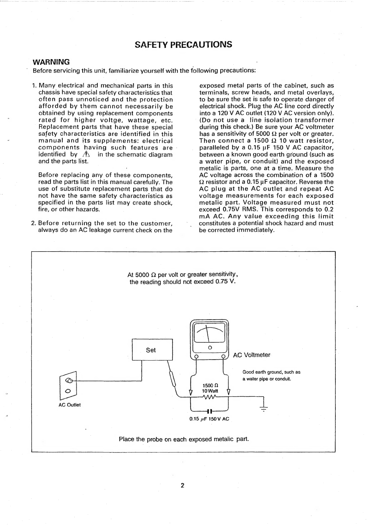
SAFETY
PRECAUTIONS
seceacSisicentencscgacshiider
vic
ctacerseuteadesconsseueecwondseetscdvosds
sbeisens
ccacsasesuvese
coocuvepecdestessoasateesea
tence
2
SPEGCIFICATHON
Siiecocecouccosc
hock
bes
ctesocaCebeeeeetecteccasihins
Riedie
sSe
ous
Galion
Ouaes
cbvees
av
riko
Th
Cesecicascuugensseaacoarsaoscdacnccasebecuosaseeey
3
WIRING
DIAGRAM
K..ccsccccessccccasccesssacectsassssccnesavccnecseinseccctesseecossredenasacnsescanssseceucedanbeccacnnseccuseuctansesevessenavenencesrs
4
BLOCK
DIAGRAM............
ucveaccevanncteacaxeudaweraricedssineansesonecadebcadevsdccacebucaaserdsavncdvectaceusysssbluucweatdagabeesescunseasecesvesse
6
TROUBLESHOOTING
waves
cccevecdesccel
doessccvevboniliecs
covoawcdiuseucde
seluedinsadcuatensen
secs
otaveusedaccbecastessseaersecesdseessesdoateeedanser
8
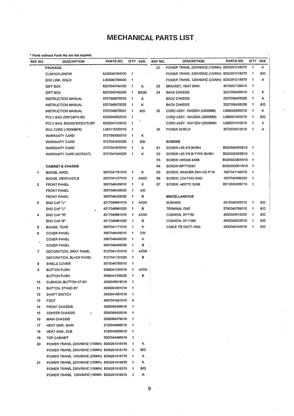
MEGHANIGAL
PARTS
LISE
sc
siscaccsausetivsdh
Gece
sucavlecteccoesacsveciedlbsseveds
nce
cvvsdseesesvedetansasesvessaseusadtaliveswenusenvaedsaders
9
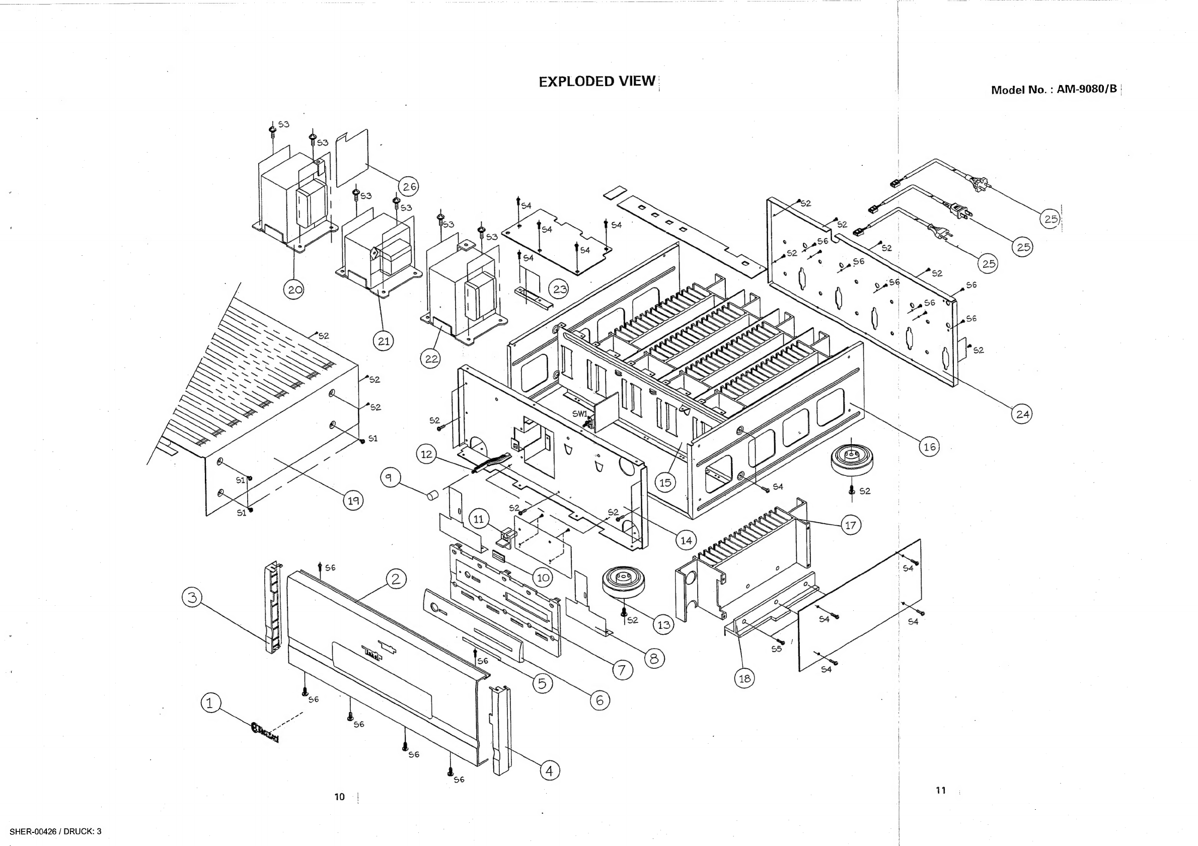
EXPEODED!'
VIEW
i.
vcicccceevsnsvnccsstagsssucdvevdecsdvectsucdest
ssanabevsiselsdetseosrcetes
teccadocnuvteocachsatbasdaaSeases
coseanasbeeaplonpeveesectans
10
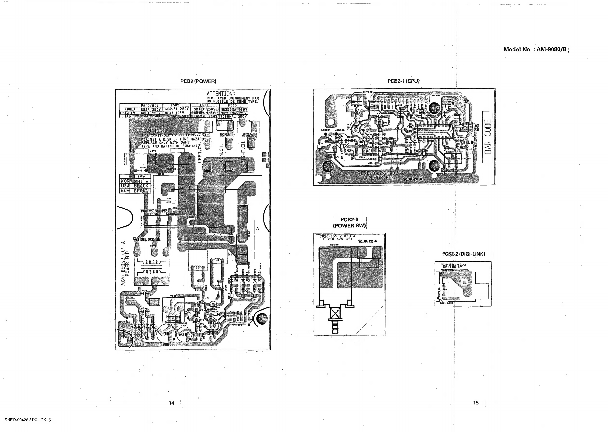
PRINTED
CIRCUIT
BOARDS.
.0....
ii
ecccie
ee
eeceececcccenessnscceceeennecenescevenseseeeaeeens
Bod
as
sxe
Sah
avodbouveleedcaetvevedeloseass
ites
12
ELECTRICAL
PARTS.
LIST
..............cccccccecsssssesseeceereneeeee
sci
Sycllaceiewh
cutie
stay
eos
Goss
obedag
ea
tiacieaes
Gensaebnek
cobeumebest
speared
16
IC’'S
FUNCTIONAL
BLOCK
DIAGRAM
..............:csssccsssssscerscecseenenereccecnensceccsccssesseeesesecesesseneeesecseeesconenssuareres
20
SCHEMATIC
DIAGRAM
(1,
IL,
Il)
.....cscssscssseessscsseesseecssesecsssseessennensscnseseeseecnscesnseesagesusenessenreesersreaees
see
sesesoees
22