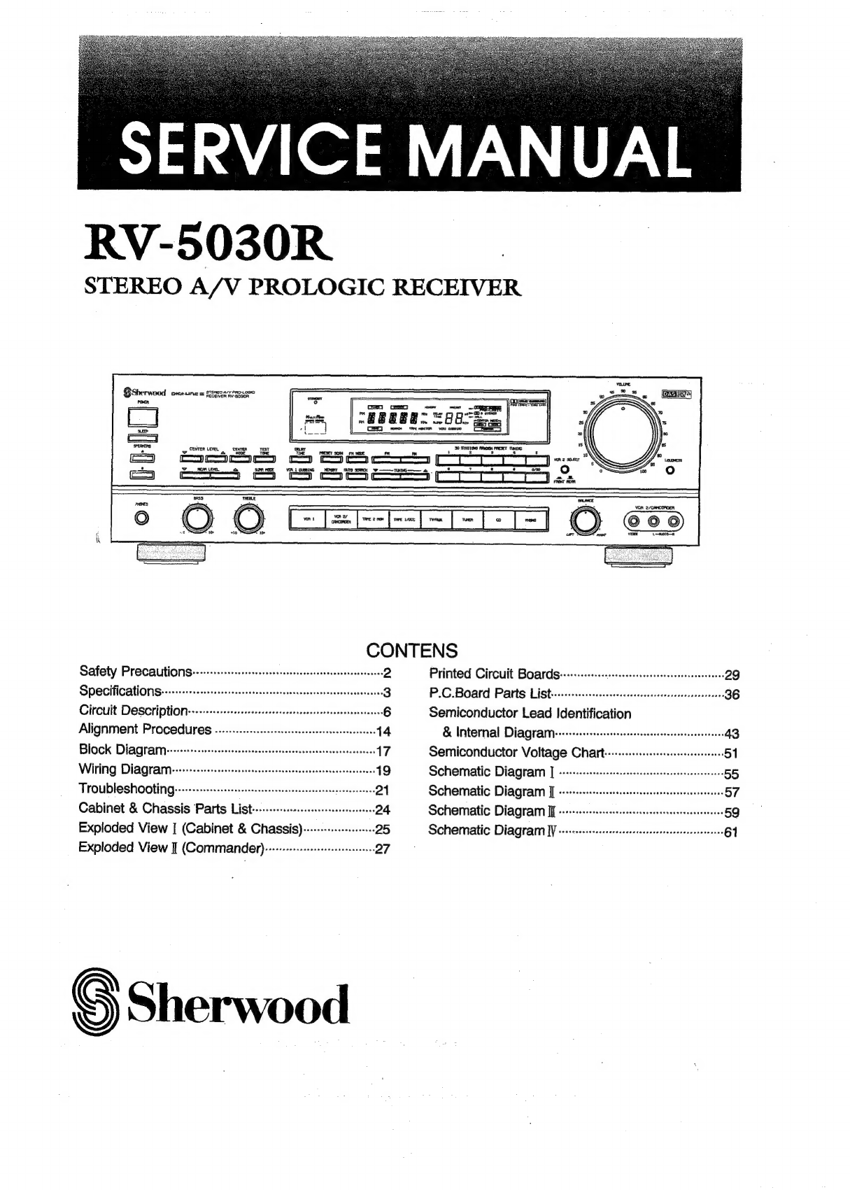
Sherwood RV-5030R User manual
Other Sherwood Stereo Receiver manuals

Sherwood
Sherwood RX-4109 User manual

Sherwood
Sherwood RX-5502 User manual

Sherwood
Sherwood R-977 User manual

Sherwood
Sherwood RX-772 User manual

Sherwood
Sherwood RD-6504 User manual

Sherwood
Sherwood RX-4109B/B User manual

Sherwood
Sherwood RX-4103 User manual

Sherwood
Sherwood S-2620CP User manual

Sherwood
Sherwood RD-6504 User manual

Sherwood
Sherwood RX-4109 User manual

Sherwood
Sherwood RX-4503 User manual

Sherwood
Sherwood RX-4100 User manual

Sherwood
Sherwood Newcastle RX-765 User manual

Sherwood
Sherwood RX-4209 User manual

Sherwood
Sherwood RX-4508 User manual

Sherwood
Sherwood RX-772 User manual

Sherwood
Sherwood RX-4105 User manual

Sherwood
Sherwood RX-4109 User manual

Sherwood
Sherwood RX-4105 User manual

Sherwood
Sherwood S-7900A User manual


Popular Stereo Receiver manuals by other brands


Pioneer
Pioneer SX-1000TA operating instructions

Yamaha
Yamaha MusicCast TSR-5B3D owner's manual

Sony
Sony STR-DE335 - Fm Stereo/fm-am Receiver operating instructions

Sony
Sony STR-DG500 - Multi Channel Av Receiver Service manual

Panasonic
Panasonic AJSD955B - DVCPRO50 STUDIO DECK Brochure & specs

Pioneer
Pioneer SX-838 Service manual