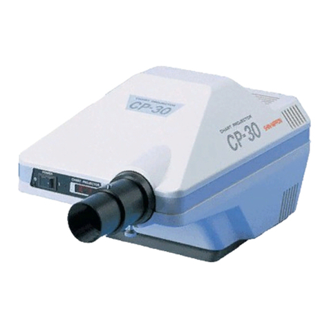
Shin-Nippon CP 30 User manual

Chart
Projector
am
an
=
5
Nm
「
ří
=
MĚ
AM
EEE
evar
mw
>
Operations
Manual
SHIN-NIPPON
1-040617

TABLE
OF
CONTENTS
1.
SAFETY
CONSIDERATIONS
レレ
スス
ミナ ナミ です
テテ
すす
2.
SAFEGUARD
SUMMERY
ーー
9
3.
NAME
OF
EACH
COMPONENT
-.-.....................
7
4.
SPECIFICATIONS
S
7
5.
SETTING
ии
LT
7
6.
OPERATING
PROCEDURE
NN
LT
8
7.
МАМТЕМАМСЕ
ии.
LT
°
8.
PRECAUTIONS
BEFORE
USE
-....................
jà
9.
COMPOSITION
RA
10.SPECIAL
TEST
CHARTS
ーー
13
11.
CLASSIFICATION
+...
m
8
12.
TRANSPORTATION
AND
STORAGE
..............
js
1.
SAFETY
CONSIDERATIONS
For
safer
and
more
effective
use
of
the
apparatus,
ihe
reader
is
asked
to
observe
ihe
following
points:
*
General
definitions
of
safety
symbols
are
indicated
below.
0
‘
General
mandatory
action.
©
No
specific
definition
given.
Denotes
general
ban
or
prohibition.
A
Warning
At
no
time
attempt
to
remodel
or
desassembie
this
machine.
(Damage
to
the
machine
or
personal
injury
will
result.)
This
machine
is
a
precision
optical
unit,
operations
must
be
carried
out
at
all
times
by
experienced,
authorized
personnel.
(Damage
to
the
machine
or
personal
injury
will
result.)

The
power
cord
must
be
firmly
connected
to
an
electrical
ground
(safety
ground)
at
the
power
outlet.
(Personal
injury
may
result
from
electric
shock
etc.)
Do
not
touch
the
optical
paris.
(Measurement
accuracy
will
be
affected.)
Always
take
great
care
when
operating
the
unit.
(Malfunction
or
damage
to
the
equipment
could
occur.)
If
the
machine
fails
to
work
properly,
the
client
should
not
try
to
repair
the
fault
themselves,
but
consult
their
dealer
immedi-ately.
(Damage
to
the
equipment
or
personal
injury
will
result.
Consult
your
dealer,
if
repair
work
needs
to
be
carried
out.)
If
a
malfunction
occurs
during
operation,
immediately
cut
the
power.
(Damage
to
the
equipment
or
personal
injury
will
result.
Consult
your
dealer,
if
repair
work
needs
to
be
carried
out.)
Never
remove
the
plug
from
the
outlet
if
your
hands
are
wet. (Electric
shock
or
personal
injury
could
result.)
Make
sure
the
power
cord
is
not
damaged.
(Fire
or
electric
shock
may
occur.)
If
the
machine
is
not
to
be
used
for
some
time,
remove
the
plug.
(Electric
shock,
leakage
or
fire
may
occur.)
0e
00e
Remark
for
setup
At
the
bottom
of
the
product,
there
is
a
uneven
part
with
cause
the
instability
at
the
usage.
So
please
use
it
which
the
special
stage.
Caution
©
Avoid
storage
or
use
of
the
machine
under
the
following
conditions:
1)
In
an
environment
where
the
temperature
falls
below
-10°
or
exceeds
+40°C.
2)
Where
noxious
gases
or
air
pollutants
are
present.
3)
In
steamy
or
moist
environments,
especially
where
condensation
forms.
4)
Where
dust
and
grit
may
occur.
5)
Where
oil
fumes
or
greasy
substances
are
emitted.
6)
Where
there
are
atmospheric
concentrations
of
salt.
7)
Near
gas
generation
areas
and
places
where
dust
accumulates.
8)
Keep
in
a
secure,
stable
situation.
Do
not
expose
to
strong
vibrations
(areas
of
seismic
activity)
and
sudden
shocks
(this
includes
transportation)
etc.
9)
Where
there
is
an
inclination
of
more
than
10
degrees.
10)
Where
the
voltage
from
the
power
source
rises
or
falls
sharply
during
loading.
11)
Where
fluctuations
in
the
voltage
of
the
power
source
occurs.
12)
In
direct
contact
with
sunlight.
Make
sure
the
indicator
of
the
voltage
selector
on
the
transformer
is
same
voltage
from
the
power
source.
Do
not
use
the
different
fuse
and
make
sure
the
power
is
off
position
and
remove
the
plug
from
the
outlet
before
changing
new
fuse.
When
not
in
use,
the
machine
should
be
protected
with
the
provided
dust
cover.
©
©
©

2.
SAFEGUARD
SUMMARY
AN
Caution
For
safer
and
more
effective
use
of
the
apparatus,
the
reader
is
asked
to
observe
the
following
points:
1)
The
power
cord
must
be
firmly
connecied
to
an
electrical
ground
(safety
ground)
at
the
power
outlet.
2)
If
the
machine
is
not
to
be
used
for
some
time,
remove
the
plug.
3)
If
a
malfunction
occurs
during
operation,
immediately
cut
the
power.
4)
Never
remove
the
plug
from
the
outlet
if
your
hands
are
wet.
5)
Similarly,
if
the
machine
fails
to
work
properly,
the
client
should
not
try
to
repair
the
fault
themselves,
but
consult
their
dealer
immediately.
6)
This
machine
is
a
precision
opticl
instrument.
Handle
with
care
at
all
times,
making
sure
not
to
accidentally
drop
it.
7)
When
cleaning
the
chin
rest
and
head
rest,
use
small
amount
of
methyl
alcohol
on
the
cotton
swab
or
soft
cloth.
1)
Make
sure
the
cords-are
not
damaged.
2)
This
machine
is
a
precision
optical
unit,
operations
must
be
carried
out
at
all
times
by
experienced,
authorized
personnel.
3)
Do
not
touch
the
optical
parts.
4)
At
no
time
attempt
to
remodel
or
disassemble
this
machine.
5)
Do
not
touch
area
around
lamp
house
while
light
is
on
or
immediately
after
putting
it
off.
It
is
extra
hot.
.
6)
Do
not
remove
the
support
racks
and
pinion
covers
on
the
table
top
while
in
operation.
Even
when
they
are
mounted,
be
careful
not
to
have
your
fingers
caught
in.
7)
TV
pictures
may
be
disturbed
by
noise
caused
by
this
apparatus.
Keep
the
two
apart
in
such
a
case,
or
do
not
use
them
at
the
same
time.
O
ο
0
3.
NAME
OFEACHCOMPONENT
(Fig.3)
Screw
removing
upper-Instrument
cover
1.
Main
unit
9.
AC
power
cord
plug
2.
Focus
adjustment
ring
10,
Control
box
3.
Projection
lens
11.
Chart/mask
selection
switches
4.
Receiver
12.
Lamp
switch
5.
Pilot
lamp
13.
AC
Power
cord
6.
Power
switch
14.
Input
plug
(AC
power
supply)
7.
Base
15.
Input
plug
(Main
unit)
8.
lamp
replacement
lid
.
4.
SPECIFICATIONS
(1)
Specifications
of
main
unit
a)
Projection
distance
:
2.0
to
7.0m
b)
Projection
enlargement
rate
:
21.5X(at
5m
distance
projection)
c)
Projection
field
:
267X267mm
(at
5m
distance
projection)
d)
Tilting
angle
:
5°
each
upwards
and
downwards
from
horizontal
level
e)
Light
source
:
12V,
30W(halogen
lamp)
f)
Dimentions
:
210(W)
X380(D)
X190(H)
g)
Weight
:
4.7kg
)
h)
Automatically
power
off
after
1Ominuts.
一
7
一

a
6.
OPERATING
PROCEDURES
(1)
Power
supply
5.
INSTALLATION
| Ш
|
(1)
Setting
of
the
main
unit
To
use
the
SHIN-NIPPON
Ophihalmic
Unit,
first,
place
the
CP-30
main
unit
on
the
exclusive
tray.
Then,
mach
two
bolt
holes
of
the
table
bottom
to
two
screw
holes
on the
projector
bottom,
and
secure
them
by
inserting
two
bolts.
Main
unit
Lock
adjustment
hole
(for
tilting
angie}
Chart
projector
Arm
Z
-
Exclusive
tray
(optional
part)
O
'
<
Y?
Bolt
hole
3
Í
1
|
©
for
ophthalmic
unit
i
Bua
(optional
part)
!
(Fig.3)
Washerfoptiona!
part)
Fixing
bolt
(optional
part)
(2)
Setting
of
the
screen
©
Projection
screen
(gray
String
crape
surface)
insert
the
provided
string
into
two
holes
at
the
upper
part
of
the
screen
and
tie
its
<
9
ends.
See
Figure
9.
一
Attach
a
hook
to
the
wall
B
ack
surface
at
the
height
of
the
patient's
eyes
and
the
(Fig.3)
.
(Fig.3)
screen
will
be
hang
horizontally.
O
Connect
the
power
cord
to
the
main
unit
and
the
AC
wall
outlet.
Then,
turn
ON
the
power
switch
on
the front
surface
of
the
main
unit.
The
chart
used
previously
will
be
released
and
the
one
at
the
start
position
will
be
automatically
on
standby.
See
Figure
2.
(2)
Projection
focusing
Set
the
projection
lens
(3)
to
the
position
where
the
lens
top
and
an
examine
will
be
positioned
at
the
same
distance
from
the
screen.
Press
the
0.1
and
0.15
switches
for
the
Landolt's
chart
(or
Snellen's
chart)
on
the
control
box
to
feed
and
project
the
chart.
Position
the
projection
lens
so
that
the
projection
image
will
be
at
the
center
of
the
screen.
Turn
the
focus
adjustment
ring
(2)
to
move
the
lens
come
forward
and
backward.
Adjust
focus
using
the
provided
test
scale
(for
2
to
7m
distance)
so
that
the
light
will
be
focused
on
the
0.1
Landolt's
(or
Snellen's)
chart.
When
the
operation
of
the
focus
adjustment
ring
does,
not
permit
an
optimal
focus,
move
the
main
unit
forward
or
backward.
See
figure
2.
(3)Operation
of
the
control
box
」
Press
any
pushbutton
(visual
acuity
and
special
test
charts,
masks,
orR&Gand
polarixation
filter),
and
any
chart
is
fed
or
changed
selectively.
The
R
&
G
and
polarization
filters,
or
various
masks
can
be
applied
to
the
projected
chart.
See
Figure
8.
(a)
Turn
on
the
power
switch
to
light
the
haloge
lamp.
At
the
same
time,
the
0.05
images
of
the
Landolt's
chart
or
Snellen's
chart
is
projected.
Even
if
an
examination
is
completed
at
any
position
of
the
chart
and
the
lamp
goes
out,
the
mask
is
released
with
the
power
switch
ON
to
leave
the
‘screen
OPEN.
The
chart
is
reset
to
the
original
point
and
the
0.05
images
of
the
Landolt's
(or
Snellen's)
chart
is
projected.
(b)
The
R&G
or
polarization
filter
is
superimposed
on
any
selected
chart
when
the
corresponding
switch
is
pressed.
Press
the
OPEN
switch
to
release
the
filter
only.
The
chart
image
remains
with
the
projection
intact.
(c)
Perform
masking
while
visually
monitoring
projected
image.
.
1)
Normally,
mask
the
0.3
to
1.5
images
of
the
Landlt's,
Snellen's,
Alphabetic,
Alphanumeric,
Numeric,
or
infant
picture
chart.
2)
Oparation
of
the
mask
Press
the
switch
of
mask
and
vertical/holizontal
mask
line
is
selected.

ν
7.
ΜΑΙΝΤΕΝΑΝΟΕ
|
>
Replacing
consumables
(1)
Replacing
an
electric
lamp
(halogen
lamp)
First,
unplug
the
power
cable
from
the
outlet.
Then,
turn
the
instrument
and
remove
4
screws
on
bottom
of
upper
part
of
the
instrument
and
remove
the
upper
instrument-cover.
Refer
Fig.1.
Pull
the
halogen
lamp
upward,
and
it
will
be
easily
detached
from
the
receptacle
in
the
lamp
housing.
Insert
the
lead
of
a
new
halogen
lamp
into
the
hole
of
the
receptacle.
Refer
Figure
10.
ANCautions
(a)
Do
not
touch
the
halogen
lamp
with
bare
hands.
Otherwise,
fingerprint
will
adhere
to
the
lamp
surface
to
adversely
affect
the
projected
light
or
chart
image.
Be
sure
to
wrap
the
lamp
with
paper
or
cloth
and
then
attach
or
detach
the
lamp.
When
the
lamp
gets
dirty,
wipe
it
using
cloth
moistened
with
alcohol.
(b)
Do
not
replace
the
lamp
when
it
lights
or
immediately
after
it
goes
out,
because
the
lamp
or
the
lamp
housing
lid
is
very
hot.
See
Figure
10.
(c}
Replace
a
halogen
lamp
with
a
spare
or
the
same
kind
of
(genuine)
part.
The 12V
and
30W
halogen lamps
very
in
size,
filament
shape,
or
diameter
of
bulb
lead
depending
on
the
manufacturer.
if
an
unspecified
lamp
is
used,
it
may
not
attached
firmly
or
cannot
yield
satisfactory
illumination
level
or
color tone.
Therefore,
be
sure
to
use
a
spare
or
a
genuine
part.
(d)
Make
sure
that
the
filament
of
a
halogen
lamp
is
properly
positioned.
The
filament
improperly
positioned
may
cause
deviation
in
illumination
level
in
the
viewing
field
even
if
the
lamp
is
not
dirty.
(e)
To
adjust
the
position
of
the
filament,
turn
on
the
power
switch
to
light
the
halogen
lamp.
Place
white
paper
vertically
at
a
distance
of
50
to
80mm
from
the
projection
lens
(3)
mounted
at
the
front
side
of
the
main
unit.
Then,
two
images
of
the
filament
in
the
halogen
lamp
will
appear
in
a
vertical
row
in
the
circular
illumination
field.
Therefore,
position
the
filament
so
that
the
two
images
will
be
identical
in
size,
providing
uniform
brightness
if
any
of
the
images
is
dim,
parted
widely,
or
deviated
sideways,
brightness
will
vary
and
illumination
level
will
be
insufficient.
Adjust
the
position
if
the
filament.
Push
the
top
of
the
halogen
lamp
with
the
handle
of
a
metal
screwdriver
(set
screwdriver)
forward
and
back
ward,
or
laterally
so
that
two
filament
images
will
be
focused
uniformly.
Be
careful
not
to
bend
the
lamp,
or
it
will
be
damaged.
See
Figure
11.
Halogen
lamp
—
7
Condenser
lens
-一
-
B
-@)
Socket
Laterally
Forward
>
=
(Fig.11)
pi
lamp
ο
Mirror
Mirror
adjusting
screw
Lamp
housing
cover.
50—80mm
White
paper
Projection
lens
at
a
distance
of
50mm
to
80mm
—
10
—
(Fig.10)
©
©
(2)Replacing
a
fuse
First,
pull
out
the
input
plug
form
the
power
receptacle
and
turn
the
fuse
holder
counterclockwise
using
a
standard
screwdriver.
Then
fuses
will
be
detached
together
with
the
holder.
Pull
them
out.
Next,
remove
the
fuse
from
the
from
the
fuse
holder.
Insert
a
new
fuse
(125V,
2A)
into
the
fuse
holder
and
screw
it
in.
See
Figure
12.
Note
that
two
fuses
are
inserted
in
array.
A
defective
fuse
cannot
be
identified
visually.
Therefore
detach
and
check
both.
(3)Replacing
batteries
in
the
control
box.
After
the
POWER
switch
is
pressed,
if
the
chart
or
mask
is
not
changed
be
pressing
the
switch
on
the
control
box,
batteries
are
considered
to
be
consumed.
Replace
the
batteries.
Push
lightly
the
arrow
mark
of
the
battery
lid
on
the
bottom
surface
of
the
control
box
and
pull
it
out.
Then
pick
out
the
old
batteries
and
replace
them
with
new
ones.
Place
new
batteries
as
illustrated
on
the
bottom
of
the
battery
housing.
Install
two
batteries
to
prevent
fluid
leakage
due
to
corrosion.
R6PU
(AA)
1.5VDCX2
See
Figure
13.
1
(Fig.12)
Tilt
angle
lock
adjustment
Base
>
0
>
$
oy
Applicable
fuse
:
250V
and
2A
(Fig.13)
>
de
y)
le)
R6PU
(AA)
DC-1.5V
Battery
housing
lid
(Fig.14)
一
11
一

8.
PRECAUTIONS
BEFORE
USE
>
(1)
install
the
projector
in
a
location
which
is
free
from
dust
and
humidity.
(2)
Keep
the
lens
free
from
dust
or
fingerprints.
Wipe
off
dust
using
a
calligraphic
brush
or
air
brush,
Wipe
off
fingerprints
or
oil
using
lens
cleaning
paper
or
clean
gauze
moistened
with
a
mixture
of
alcohol
and
ether.
(3)
The
CP-30
is
a
precision
optical
instrument.
Handle
it
carefully
during
transportation.
(4)
When
the
tilting
unit
tends
to
keep
facing
downward
or
upward,
tighten
the
two
tilt
angle
lock
adjustment
screws
on
the
back
side
of
base.
Figure
14.
9.
COMPOSITION
©
-
Standard
composition
Projector
тат
unit
fm.
1
Control
box
+1
Screen
......
ㆍ
“|
Power
cable
"1
Test
scale
sheet
ㆍ 아 아 사 사
아아아
1
Optional
component
.
Polarization
filter
with
a
bar
R &
G
glasses
with
a
bar
Chart
card
(ior
training)
OPC
で
で で で
ドド
と
ドド
1
Vinyl
cover
Spare
lamp
(12V
and
30W
halogen
lamp)
:
Spare
fuse
(250V,2A)
+++
iii
iii
1
一
12
一
(
10.
SPECIAL
TEST
CHARTS
Astigmatism
chart
Employed
to
identify
astigmatism
and
find
the
astigmatic
axis.
The
astigmatic
axis
index
(red)
shifts
when
the
chart
33123
10,
2
9
3
8 4
765
is
turned.
Red
green
test
Monocular
examination
@Evaluation
of
latent
hyperopia,
anddetermination
of
excessive
or
insufficient
correction
of
myopia,
or
identification
of
insufficient
correction
of
anisometropis.
@The
emmetropia
or
excessively
corrected
eyes
can
see
both
red
and
green
test
targets
clearly.
@The
hyperopia
or
excessively-corrected
myopia
can see
the
target
against
the
green
background
more
clearly.
@The
myopia
or
excessively-corrected
myopia
can see
the
target
against
the
green
background
more
clearly.
900
oo
Lo
4
Point
group
chart
Determines
the
degree
of
precision
of
asatigmatism
lens
when
used
in
conjunction
with
the
vision
tester
cross
cylinder.
Duochrome
balance
Le
Binocular
examination
Paralyzation
©"
|
method
@Fine
adjustment
of
binocular
spherical
lens
and
establishment
of
corrected
binocular
balance
for
normal
binocular
vision.
@Each
eye
observes
both
lengthwise
and
sideways
figures
due
to
poralization.
Right
eye
:
Green
(9)
and
red
(6)
Left
eye
:
Green
(3)
and
red
(5)
In
the
same
manner
as
the
normal
red
and
green
test,
the
variation
in
brightness
of
two
numerals
demonstrates
whether
or
not
correction
has
been
undertaken
satisfactorily.
@This
test
has
proved
to
be
effective
for
examination
of
ametropia
among
young
people.
It
is
also
effective
for
evaluation
of
dominant
eye,
altemate
fixation,
or
abnormal
suppressed
eye
muscle
balance
(perpendicular
or
horizontal
heteroporia).
Cross-line
grid
(or
corss
-hair
lies)
This
grid
is
employed
to
evaluate
prebyopia
when
used
in
conjunction
with
10.50
Cross
Cylinder.
In
general,
this
grid
is
printed
on
the
near-point
card
of
a
vision
tester.
The
forsighted
spectacle
level
is
examined
and
and
then
used
to
correct
the
vision.
Then,
an
optimal
spectacle
level
at
a
near
point
is
examined.
Note:
Ask
the
examinee
which
looks
darker,
the
vertical
or
lateral
line.
@in
case
of
prebyopia,
the
lateral
line
looks
darker
and
the
vertical
line
dim.
(When
both
the
vertical
and
lateral
lines
look
identical
in
darkness,
farsighted
glasses
are
not
necessary.)
O
Advance
the
spherical
lens
in
the
+
direction
by
0.25
D
until
both
the
vertical
and
lateral lines
look
identical
for
darkness.
@When
the
vertical
lines
are
seen
darker
and
the
lateral
lines
dim,
the
vision
is
corrected
excesssively.
Therefore,
decrease
the
correction
Binocular
refractive
level
until
both
the
vertical
and
lateral
lines
have
the
same
degree
of
darkness.
Binocular
refractive
balance
test
Binocular
examination,
Paralyzation
method
@Examination,
of
balance
of
refractivity
and
visual
acuity.
@Polarized
light
demonstrates
either
of
the
upper
and
lower
target
(05, 0.6,
0.8, 1.0,
or
1.2
acuity
value)
for
each
eye
alternatively.
However,
normal
binocular
vision identifies
the
target
as
the
original
test
target.
This
comparison
demonstrates
whether
or
not
acuity
balance
is
normal.
@When
the
target
is
observed
a
being
overlappped
or
deviated,
latent
hetero
phoria
is
identitified.
一
13
一

Worth
test
+
+
Binocular
examination,
R &
G
o
complementary
coloring
@Rough
examination
of
binocular
vision.
OThe
R 8
G
filter
is
used
to
examine
the
visualization
of
a
dot.
For
example,
assuming
that
a
red
filter
is
applied
to
the
right
eye,
and
a
green
filter,
to
the
left
eye
:
When
two
red
points
appear,
the
image
on
the
left
eye
is
suppressed.
When
three
green
points
appear,
the
image
onthe
right
eyes
is
suppressed.
When
four
green
points
appear,
binocular
vision
is
normal
and
a
remakable
abnormality
derived
form
an
imbalanced
eye
muscle
is
not
identified.
When
five
green
points
appear,
both
eyes
function.
However,
the
fusion
of
the
lower
dot
with
-
different
color
is
weak,
suggesting
plopia.
Therefore,
another
examination
for
convergence
required.
©
Binocular
examination,
R
&
G
complementary
color
method,
in
a
completely
dark
room
@Latent
heterophoria
examination
method
invented
by
Dr.Schober.
©
Have
the
examine
view
the
target
with
bare
eyes.
Then
apply
a
green
filter
to
one
eye
and
a
red
filter to
the
other
eye.
A
red
cross
is
seen
through
the
red
filter
and
a
green
ring
is
seen
through
the
green
filter.
@When
the
cross
is
seen
to
be
deviated
from
the
ring,
latent
heterophoria
is
identified.
@The
ring
diameter
is
2P
dpt
and one
section
of
the
red
cross
is
1P
dpt.
Schober
test
(Cross
ring
test)
|
Phoria
test
ms
q
aa
|
Binocular
examination,
Poralization
I
method
@When
the
poralization
filter
is
employed,
the
right
eye
observes
only
the
right
lower
part
of
the
cahrt,
and
the
left
eye,
the
left
upper
only.
@An
abnormality
of
each
eye
is
assessed
in
terms,
of
variation
and
dislocation
of
horizontal
and
perpendicular
lines,
and
in
combination
of
다
lines
as
a
cross.
~
@The
lateral
variation
of
a
cross
demonstrates
À
exophoria.
Г.
1
method
Li
1
@ldentification
of
retinal
aniseikonia
and
vertical
or
horizontal
heterophoria.
@The
center
dot
is
used
to
combine
(and)
figures
across
the
dot.
@The
right
and
left
images
in
different
sizes
demonsirate
aniseikonia
on
the
perpendicular
or
horizontal
meridian.
The
patient
with
aniseikonia
is
susceptible
to
headaches
and
cannot
work
when
at
a
short
distance
viewing
is
required.
He/she
cannot
enjoy.
V
Coincidence
test
Binocular
examination,
Polarization
I 1
Haploscopic
vision
test
e Binocular
examination,
Polarization
|
|
method
@Stereo
examination
for
assessmment
of
far
special
vision.
@With
polarized
light,
upper
lines
are
seen
backward
with
respect
to
the
fixation
point,
and
lower
lines,
forward.
For
normal
stereoscopic
vision,
the
lines
are
seen
at
a
position
1/3
nearer
than
that
seen
by
abnormal
eyes.
@For
very
light
esophopria,
two
separately
polarized
lines
are
seen
fused
inside
the
fixation
point.
The
backward
part
of
the
lines
is
also
fused
into
a
single
line.
-
@When
two
lines
are
overlapped
or
seen
separately,
a
defect
in
fusion
is
identified.
In
case
of
esophoria,
the
prism
correction
allows
the
patient
to
perceive
the
backward
figurs
as
clearly
as
the
forward
part.
For
a
patient
with
exophoria
with
sufficient
fusion,
a
figure
is
easily
fused.
However,
it
takes
some
time
to
focus
on
the
output
forward
image.
When
the
lines
do
not
appear
on
the
perpendicular
line
passing
the
fixation
point
but
appear
across
the
line,
monocular
dominance
or
suppression
is
suggested.
©
一
14
一
a
11.
CLASSIFICATION
Chart
projector
CP-30
complies
with
Medical
Device
Directive
93/42/EEC.
1)
Classification
by
the
type
of
protection
against
electric
shock.
Class
|
instruments
2)
Classification
by
the
extent
of
protection
against
electric
shock
Class
B
instruments
3)Classification
by
the
extent
of
protection
against
harmful
infiltration
of
water
Ordinary
instruments
(instruments
with
outer
coverage
not
protected
against
water
infiltration.)
4)
Classification
by
in-service
mode
O
Short-time
operation
12.
TRANSPORTAION
AND
STORAGE
When
transporting
the
machine,
make
sure
the
following
environment:
TEMPERATURE
HUMIDITY
0—40C
20~80%
(Transportation
and
storage
in
the
only
package)

EU
Representative
FAUSTO
GUZZETTI
(SHIN-NIPPON
TECHNICAL
CENTER)
VIA
SOLFERINO,5
21057
OLGIATE
OLONA(VA),
Italy
Supplied
by
AJINOMOTO
TRADING
INC.
SHIN-NIPPON
Medical
&
Ophthalmic
Instruments
Dept.
©
EAST
WING
7TH
FLOOR,
TFT
BUILDING
3-1-22
ARIAKE,
KOTO-KU,
TOKYO
135-8071,
JAPAN
TEL:
813-3528-4416
FAX:
813-3528-4426
-
http//www.shin-nippon.jp
Le
Manufactured
by
:
TOWA
MEDICAL
INSTRUMENTS
Co.,Ltd.
1698-2
Oaza
Nakano
Nakano-shi,
Nagano-ken,383-0000
Japan
+
Please
do
not
dispose
this
product
as
unsorted
municipal
waste.
+
Please
inquire
the
distributor
about
the
return
and
the
collection
system.
Other manuals for CP 30
1
Table of contents
Other Shin-Nippon Projector manuals
