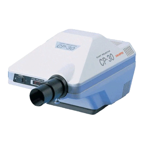
Shin-Nippon CP 20 User manual

service
Manual
for
CP-20/30/40
Chart
Projector
SHIN-NIPPON

CP-40
ITEMS
OF
REPAIR MANUAL
1.
DISASSEMBLING
OF
THE
LOWER
CASE
2
DISASSEMBLING
OF
THE
UPPER
CASE
3.
CHANGING
THE
WAVE
LENGTH
4.
HOW
TO
CHANGE
THE
CONDENSER
LENS
HOW
TO
CHANGE
THE
REFLECTION
MIRROR
HOW
TO
CHANGE
THE
CHART
BOARD
HOW
TO
CHANGE
THE
PC
BOARD
CO
<a
D
ο
HOW
TO
CHANGE
THE
POWER
SOURCE
BOARD
9.
HOW
TO
CHANGE
THE
MAIN
SWITCH
10.
HOW
TO
CHANGE
SENSOR
11.
HOW
TO
ADIUST
THE
CHART
BOARD
AND
THE
MASK
BOARD
12.
DISASSEMBLING
OF
THE
VARIABLE
POWER
LENS
BARREL

HOW
TO
USE
THE
REPAIR
MANUAL
(1)
(2)
(3)
(4)
(5)
(6)
(7)
Please
keep
in
mind
the
followign
procedure
before
repairing.
PROBLEM
UNDERSTAND
THE
CAUSE
OF
THE
PROBLEM
IT
MUST
BE
REPAIRED
=
一
一
一
一
REPAIR
|
CHECK
|
=
WORKING
PROPERLY
|
CLEANING
|
PACKING
|
END
Please
disassemble,
repair,
assemble
and
adjust
the
optical
system
in
clean
surroundings
so
the
machine
will
not
be
damaged
by
dust.
When
repairing,
be
sure
to
follow
the
instructions
of
this
manual
using
the
correct
materials
and
implements.
For
the
hardware,
replace
by
part.
For
the
electric
system,and
the
optical
system,
replacements
are
basically
executed
by
unit.
As
for
the
disassembling
and
assembling
of
parts
not
mentioned
in
this
manual,
refer
to
the
service
part
list.
Do
not
use
any
other
lubricant
than
the
one
mentioned.
Order
a
replacement
part
referring
to
the
servie
part
list.
(1)

”
I
!
2.
PRACTICAL
REPAIR,
(Procedure
of
disassembling,
checking,
and
adjusting
)
Sketch
|
Procedure
(1)Disassembling
of
the
lower
case
1.Remove
the
6S
4x6(#3) screw
and
remove
the
base.
2.Pull
out
the
connectors
on
the
P.C.
board
and
the
power
source
board.
3.Remove
the
four
CR
3x5(#4)
screws.
4.Remove
the
CR
4x12-SW(#1)
screw.
5.Remove
two
CR
4x8(#2)
screws.
Base
(2)
A
VIEW

2.
PRACTICAL
REPAIR
(Procedure
of
disassembling,
checking,
and
adjusting
)
Sketch
ED
Lo
À
ER
Remote
Control
Board
A
—
Procedure
(2)Disassembling
of
the
upper
case
|
1.Remove
the
CR
4x10(#5)
©
2.Remove
it
from
the
back
side
of
the
case
in
the
direction
of
the
arrow
((3)Changins
the
wave
length
*Remote
control
side
l.Remove
the
batteru
from
the
case
2.Remove
the
TCB2x8
screw
which
is
on
the
opposite
side
of
the
remote
control.
3.Slide
the
back
caase
back
Identification
Plat
Battery
case
|
4.When
removing
the
back
case,
|
the
board
of
remote
control
|
appears
and
the
wave
length
can
be.
|
changed
by
a,b.
|
|
*
Machine
side
l.Implemented
with
the
dipswitch
on
|
the
board.
(3)

©
Condenser
lens
sketch
|
Procedure
(4)How
to
change
the
condenser
lens
1.Remove
the
sight
CR
3x6-FW(#6)
screws.
2.The
condenser
lens
is
removed
when
the
6W
3x5(#7)
screw
is
loosened.
Holder
ホル
レダ
ザー
(86)
.
CR3X6-EW
_
(#3)
αντ
LA"
|
(5)
How
to
change
the
reflection
mirror
1.Reflection
mirror(#10)
is
detached
when
the
three
positioining
screws
are
removed
(3)
64:09)
Positioning
screw
Positioning
spring
(Rek
|
A
Reflection
mirror
AO
wean
.
Fr
A
D
(4)

Sketch
(6)How
to
Remove
Remove
(JL).
Procedure
change
the
chart
board
the
the
the
located
in
1.
2.
3.Loosen
4.
CR
4xli-SFW(#11)
connector
of
the
motor
6W3x5
screw
which
is
the
A
part.
L
4.Apply
paint
thinner
on
the
©
С
xle-sF
+10)
rotation
axis
of
the
motor
and
remove
the
chart
board
(#12)
(7)How
to
change
the
mask
board
!
l1.Remove
the
CR
4x12-SFW(#13)
|
2.Remove
the
connector
of
|
the
motor
(J2)
3.Loosen
the
6W3x5
screw
which
is
located
in
the
A
part.
4.
Apply
paint
thinner
on
the
roration
axis
of
the
motor
and
(0)
remove
the
mask
board
(#14)
CR
4xl2-SHN
(#13)

Sketch
Procedure
|
(8)How
to
change
the
P.C.
board
l.Remove
connectors
(1-6)
2.The
P.C.board
detaches
when
the
CR
2.6x6(#15)
screw
is
removed.
Connector
(9)
How
to
change
the
power
source
board
i.Remove
the
65
4x16(#16)
screw
P.C.Board
and
remove
the
base
(#17).
2.The
power
source
board
(CP-40
1027)
detaches
when
the
CR
3x5
screw
on
the
unit
stand
is
removed.
(6)

Sketch
Procedure
(10)How
to
change
the
main
switch
1.Pull
out
the(#18}(CP-40
1039)
lock
boards.
2.Take
off
the
solder
which
is
on
the
switch
and
pull
out
Lock
board
the
switch
by
raising
its
pawl
(#19)
419)
Switch
|
eum.
(11)How
to
change
the
sensor
Sensor
window
1.Remove
the
connector
of
the
|
зепзог
(23,44)
2.Remove
the
CR
3x15-FW(#20)screw
3.The
sensor(#22)
detaches
when
is
removed.
remove
the
mask
board
(#14)
|
|
(4.20)
(421)
CH22)
CR3x|5-
6x6
TLPE
ン
サー
11-
lg.
|
Sensor
holder

How
to
adjust
the
chart
board
and
the
mask
boardírefer
to
CP-40
part
list.)
1.
Tighten
the(CR4x12-SFW)
screw
which
holds
the
bracket
(CP-40
1011)
in
place.
2.
insert
the
connector
of
the
motor
into
Jl,
J2.
3.
Put
the
chart
board
and
the
madk
board
between
the
sensors.
(Note)
(1)
Set the
chart
board
and
the
mask
board
as
closely
as
possible.
(2)
Be
sure
that
the
pola
dileter,
the
R.G.filter
which
in
on
the
chart
board,
and
the
mask
board
are not
touching
the
sensor
and
the(CP-40
1011)
bracket.
4.
First,
tighten
one
of
the(6W
3x5)
screw
which
is
pressing
the
chart
board
and the
mask
board.
5.
O
will
be
displayed
on
the
screen
board.
(Note)
O
will
not
be
displayed
when
the
chart
board
and
the
mask
board
are
set
diagonally.
6.
Adjust
the
up
and
down
position
of
the
screen
displayed
with
the
6-W
3x5
screw.
Adjust
the
right
and
left
position
with
the(CR
4x12-SFW)
SCrew
which holds
the
bracket.
7.
Lastly,
tighten
the
other
(6W
3x5)
screw
ehich
you
have
not
yet
tightened
in
(4)
and
adjust.
(8)

‘+
Disassembling
of
the
variable
power
lens
barrel
(Refer
to
CP-40
part
list.)
1.
Fig.6
(11)
Remove
four
CR4x8
screws.
2.(3)
Totally
withdraw
after
removing
the
back
side
of
the
upper
lid.
Fig.1
(10)
Remove
CR4x8
SW
screw.
Make
the
CR3x5
screw(2)
which
are
on
the
adjust
ring
(1)
into
the
up
and
down
position
and
pull
out
the
variable
power
lens
barrels
(1)-(8)
from
the
body
(9).
Remove
the
two
CR3x5
screws
(2)
and
remove
the
adjust
ring
by
rotating
it.
(Note)
Be
careful
because
the key
may
fall
6.
7.
10.
Remove
the
ring
nut
(3)
by
rotating
it.
Remove
the
lens(4)
by
poking
it
from
the
opposite
side
of
the
lens
pipe
(8)
with
something
that
will
not
damage
it
(such
as
ball-point
pen
that
is
plastic
plated).
Put
a
new
lens
in
the
lens
pipe
(5),
making
sure
that
the
convex
faces
the
outside.
Fasten
it
securely
with
the
ring
nut
(3).
After
confirming
that
the
key
(6)
is
set
in
both
the top
and
the
bottom
of
the
lens
pipe
groove
(8),
screw
in
the
adjust
ring
(1)
until
it
comes
to
the
position
where
it
fits
the
screw
hole
of
the
key
(6).
Then,
secure
it
temporarily
with
one
CR3x5
screw,
and
reverse
it
and
set
another
one.
Set
both
of
them
firmly
by
turning
and
observing
the
adjust
ring.
(9)

11.
12.
13.
<>»
insert
the
variable
power
lens
barrel
(1)-(8)
in
the
body
{9),
so
the
screws
are
in
an
up
and
down
position.
Confirm
the
screw
hole
position
by
turning
the
variable
power
lens
barrel
and
secure
it
firmly
with
the
CR4x8-SW(10)
screws.
Confirm
whether
or
not
the
diode
on
the
board
is
inserted
in
the
panel
hole
(5)
(if
not
push
the
diode
into
the
hole
using
your
finger).
Then,
cover
it
with
the
upper
lid
(3)
putting
in
the
panel
side
(5)
first.
(Note)
Be
sure
that
the
wiring
code
of
the
sensor
does
not
get
14.
caught.
(11)
Tighten
the
four
CR4x8
screws.
(Note)
Be
careful
not
to
secure
them
too
tightly.
(10)

.
wm
Chart
of
the
function
of
the
dip-switch
of
CP-20
and
CP-40:
No.
of
Dip-switch
|
function
Description
Mode
dip-swich
of
PC
board
of
1,2
Remoto
control
CP-20/40
Remoto
Unítr
.
A
mode
|5W2-on,
SWl-on
(b)-SH,
(a)-SH
mode
C
mode
|SW2-on,
SWl-off
i(D)-SH,
(a)-RX
B
mode
j(SW2-0ff,SWI-on
|[(b)-KX,
(a)-SH
D
node
|[SW2-0ff,SWI1-0ffi(b)-KK,(a)-XX
tsH=jJumper
shut
=XX=jumper
open
on
PC
board
of
Remoto
Unit
Ccontrol
Box
)
3,4,5
Distinguish
СР-20
SW3-on
CP-20
or
Cp-40
CP-40
SW5-on,
SW4-off,
SW3-off
"6.
Auto
power
off
|
SW6-on
"Auto
off
function"
ON
o
function
(Auto
power
off
approx.
19
on
/
off
min.
with
no
operation)
SW6-off
“Auto
off
function”
OFF
7
Buzzer
on
/off
SW7-on:
Buzzer
ON
SW7-off:
Buzzer
OFF
6
Test
Made
SW8-off:
Normal
(Operation)
mode
-
SW8-on:
Test
Mode
SWi-on:
Adjustment
mask's
position
SWi-off:Adjustment
chart's
position
jPlease
note
that
new
function
of
re-setted
dip-switchs
will
effective
after
re-seting
of
the
Main
Switch.
e
rumo
“as

DE
E
HS
M
Е
за
с
B
m
m
sa
HE
E
Em
a
и
」
a u
L'or
0х
Ш
AAA
개제
HE
A
TT
5
A
o»
Y
~
0
RH
„0
Ei
Wi
08/06/0049
VOTE.
800
+
Y
|
|
we
|
Res
|
/
my
ママ
.
2
pe
圖
o
=
mi
TE
DAY
21
a
TENE
—
İST
ODAYI
7
fr
|
no
ML
NUL
SB
(om
-
Y
04665
Li
.
“
зьяе
F
|
3
(48510
=
VLOSHIL,
6-30
|
|
Г-2!-
093
.
-BRA
LEE
:
OS
-634-4
0
COEN
,
m
M
(49
DD:
.
terna
6/
10:
veo.
caera
JD
o
(EN)
-H4ob
KE
OS
|
C
neo
če
Ad
.
|
.
©
8
a
(UD
TAO
(1315)
19
ENI
VLOSATE
©
ayi
ng
frame
|
02627
ーー
all
y
Y
04
ELE
ーー
ПИ:
MELEK...
29
400
一
一
o
,
sa
a
ét
110
At
Ge
밀수
gets
-
047=7
DMB
EZ
Hi
ftw.A021-00194Y
È
bug
130HS
—
よ
キ
アロ
イミ
.
-
7
7
=
©
+
NE
ご
+
T
zd
N
lo
T
315-17.
LAVE
기는
+
FT
ET
rentes

1210
-34V
"ON
ONIMVHQ
NT
IO
E
cp
VE
Cl-40Sd
|
AB,
NMVYO
8
036491530
"ON
“ICON
7
f
8861
4
SINAIS
cava
8
OANOAHO
É
ham
di
、
ae
m
|
|
|
|
|
|
|
y
++
|
i
wg
yl
|
ou}
em
gt
"|
vs
|
mi,
AR
—
|.
y
19321
ana
[TT
a
ww
|
^
x)
y
|
티비
μα
Zod
Taz
SSH
|
N
|
ges
ten
|
Stu
eta]
e
813
ry
L
19
AS
i
ARA
yw
一
YY
一
ve
中
i
로
eres
IS
u
vw
\
(AN
2
ς 193
引
RE
mod
po
[Est
osu
.
|
ma
|
3
г
8
ZW
csu
|
158
o
|
nad“
M
zlaz
|
149
ーー
9
T T
AGD
.
79 ER
7)
4000
200!
11048
Der
.
919
©
_
E
INi
15031
$
|
Yo"?
A
人
TA?
|
UML
o
AD?Z-102
AZI
è
|
20
=
LER
=
7/^001~00[
#
asy
ISH
2
sw za
T
M
113
NE
OV
easy
uu
.
|
©
(1)
SS
um
na
_
—
ーー
|
|
|
=
—13$09—
did
no]
|
о
oly
0
x

cu
ο
.
tik
M
我
y
Я
.
+
.
HH)
-
.
村
sir
M
看望
ten
—
00800)
Ha
マ
Reed
|
„EOF
0
下。
097
一
多
,
"
93
-
Ip
dy
al
EST
LAR.
LEZ.
lat
pu
201
OF
・
V
|
yem
EEE
и
|
Y
314
10038092
024)
.
Si
=
DEE
こ
つう
-
DEE
OH
ES
BURdPOO
HA-dee
=
OND
ASE
NOL
P
HA=dEE
E
ino
89
GES
M
£—|
boa
xi
Ougdbon
Jp
TSIH
AE
'BANODEE
ἐν
al
SHEwtyOD
so
FRED
vez
SA
2
SDA
AE
BANODDI
느는
να
ES
<.
L-
så
EHEdrOD
955
=
=
ADI
AND
fs
JHE-
dre
品
个
söze
8
osa
.
5824
£
DA
in
M22
Seuss
29
于
ee
DÍA
τος
tri
κ
Y
bed
9342804
РО
289855
>.
SSLpOD
.
3H5-
450
コロ
ョ
ー ロ
8
・
552%
088
SSE
ST
au
pis EFE
JOTEDL
^
DELL
HSE
|
sui
Skt
dPOD
.
Estar
HSSADS
3N;
19
Sivoo
η
7
pEZvi
#02204
-
Hardee
Zo
BELİ
MEZ
9
HA-dE8B
PHI
¿Sun
+
T
©
-
tol
À,
Ze
INIW
.
やど
マト
NB
56Р-х
EHI
622
dI0S2E
x
DDA
ZMOLELER
TOA
>
ヒュ
ーー
BEST
`
вн
で
す
一
し
し
|
JDA SSA
op
モト
ニー
ši
4544
|
inox
-E
Su
ГЕ
Bi]
DES
NIX
TF
EX
ona
SHE
MELL
7]
LEd
ABBA
{ODA
TY
OB
|
2Ed
Oza
be
AEV
HYDE
é
E]
PES
Les
102201
.
_
|
Prey
E
Tra
=
2
THE
E]
dou
Eee
LE
.
DOEdIOGI
o
1554
оса
|
Log bid
po
一
.
DEcIOSY
205
Sl
AHS-SLE
=
SFERE
3—8
E08
Eld
ba
7
é
ted
END
EMO
AA
4
p
T-
セロ
ロ
piel
EE
HS
aLe
A)
ND
uo
pS
DAM
‘Sse
72
БЕ]
вон
sid
Le
E
:
TE
rd
andò
80Λ
LE
504
DE
BE)
504
Sra
[E
XE
=
LO
+A
É
FODA
pr
TEST
BEI
と
Og
ενα
|-
ES
|
Gai
L
ad
bno
ΨΝΙ
Ρ
Sil
eno
ENI
pet
202.
Ed
Z
200
eNI
bé
£
b
3H5-d96
gHS-408
“amina
ルル

ο
συ
a
ㆍ
ㆍ
fh
H
Wa}
UYUCUCd
OF
f0F
09-69
#
=
>
ー
|
У
us
ges
sa
|=.
+
TES
x
BW
| |
|
PER
goa
vor
oY
V
A
VOTE
SOOFV
ATI
—
Fetih
Y
Le
г.
fi
©
m
au
αι
RES
E
HAM
se
-
М
+
|
|
一
er
|
hr
+
|
Г
d
À
Sal
7
x
pe“
È
=
I
o
|
>
Sf
TZB
|
ot
20
ト
U
+
ALON
do
VA
LY
M
N
gol
oy)
ody
MN
Other manuals for CP 20
1
This manual suits for next models
2
Other Shin-Nippon Projector manuals
