2
General Safety Instructions
Contents
Introduction
PAGE
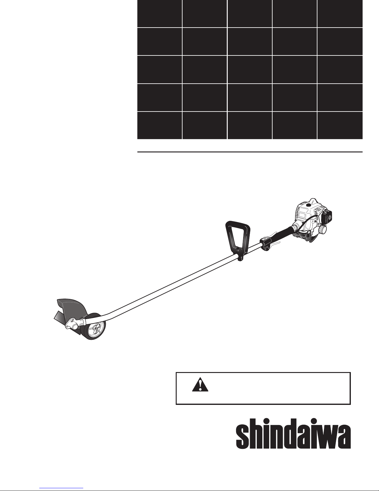
Shindaiwa 230-series hand held power
equipment has been designed and built to
deliver superior performance and reliability
without compromise to quality, comfort,
safety or durability.
Shindaiwa’s high-performance engines rep-
resent the leading edge of 2-cycle engine
technology, delivering exceptionally high
power with remarkably low displacement
and weight. As an owner/operator, you’ll
soon discover for yourself why Shindaiwa is
simply in a class by itself!
IMPORTANT!
The information contained in this owner's/
operator's manual describes units avail-
able at the time of publication.
Shindaiwa Inc. reserves the right to make
changes to products without prior notice,
and without obligation to make alterations
to units previously manufactured.
Attention Statements ...................................2
Safety Information ........................................2
Safety Labels .................................................4
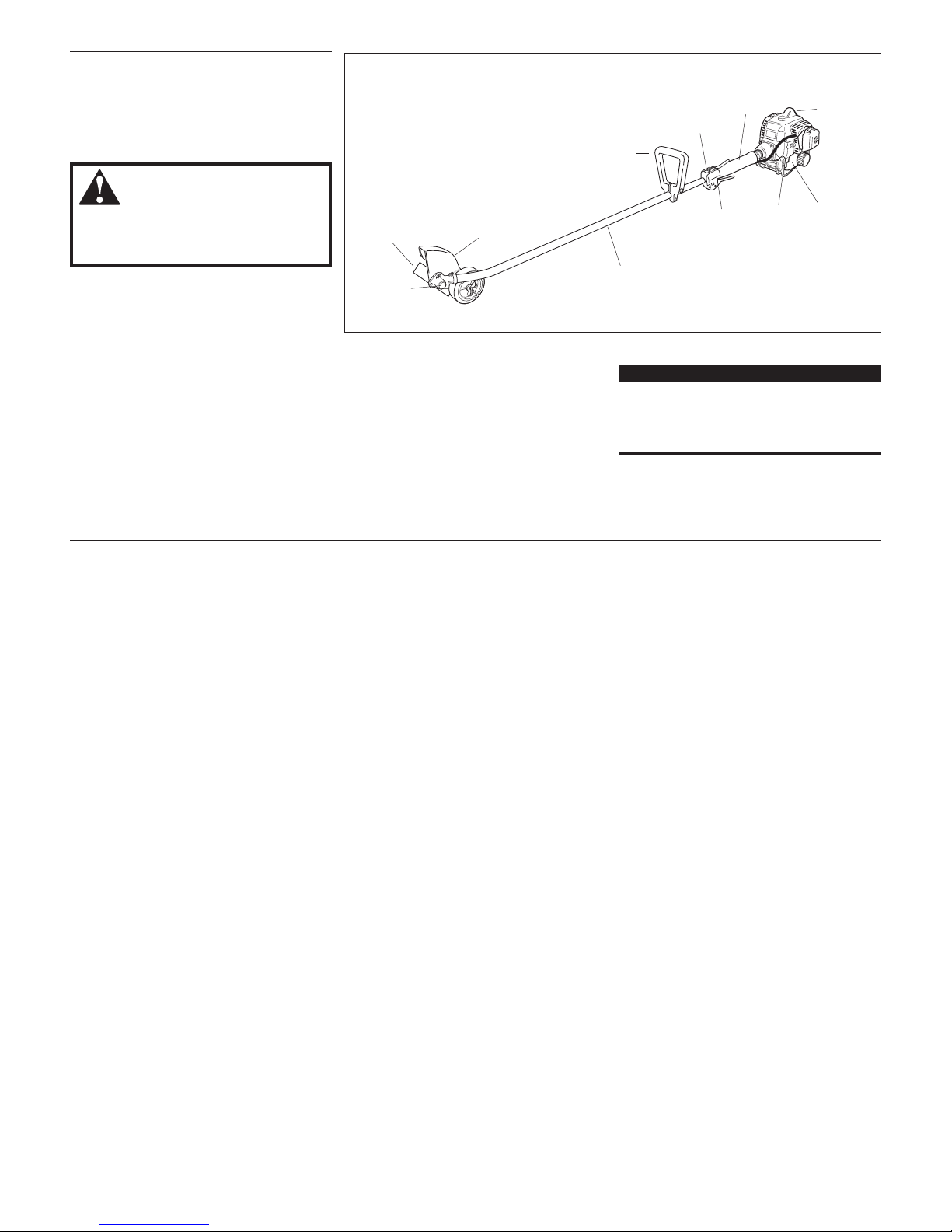
Unit Description ...........................................5
Specifications ................................................5
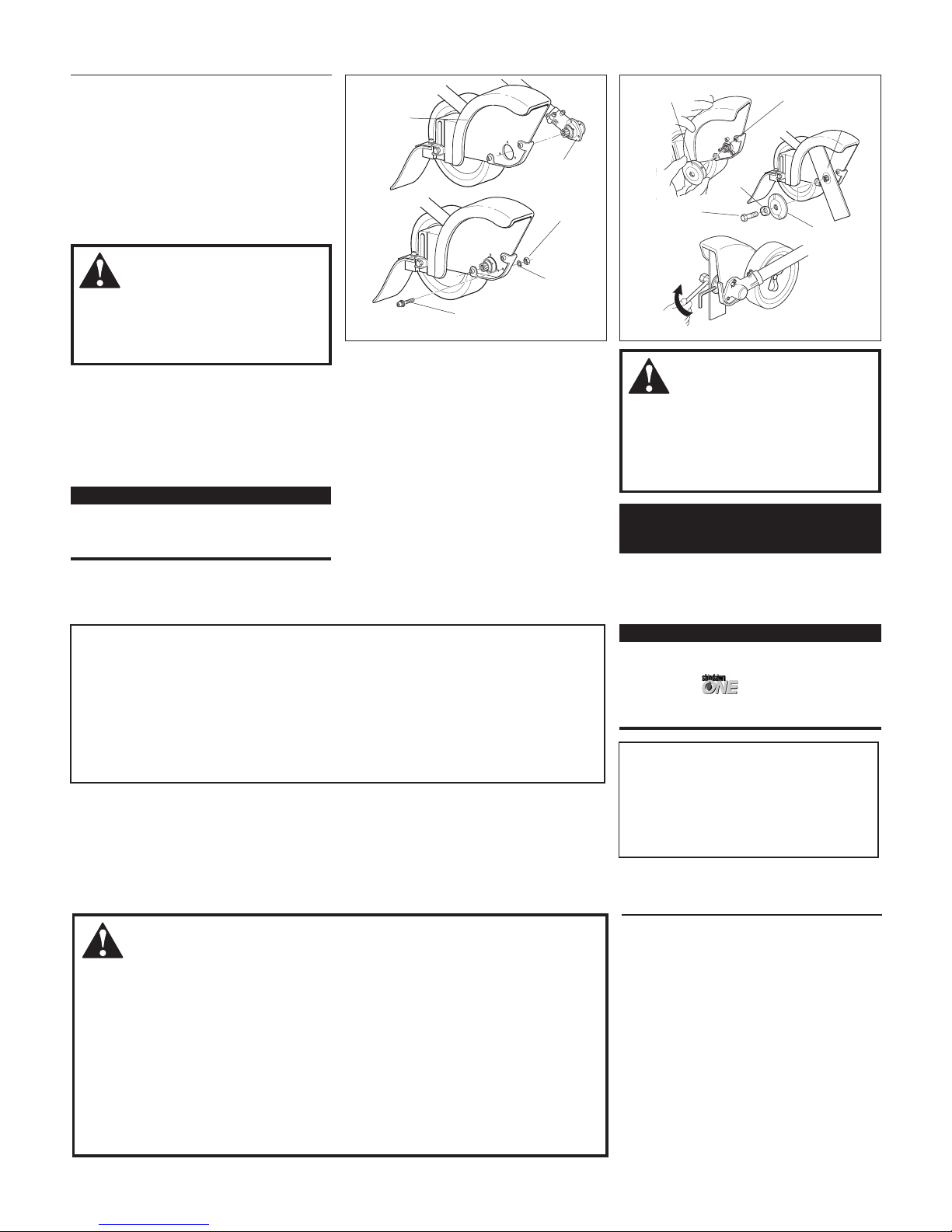
Assembly .......................................................6
Mixing Fuel ..................................................8
Starting the Engine ......................................9
Stopping the Engine ....................................9
Engine Idle Adjustments ...........................10
Checking Unit Condition ..........................10
Using the Edger .........................................10
Maintenance ...............................................11
Long Term Storage ....................................14
Troubleshooting Guide .............................15
Emission System Warranty .......................17
WARNING!
The engine exhaust from this unit con-
tains chemicals known to the State of
California to cause cancer, birth defects
or other reproductive harm.
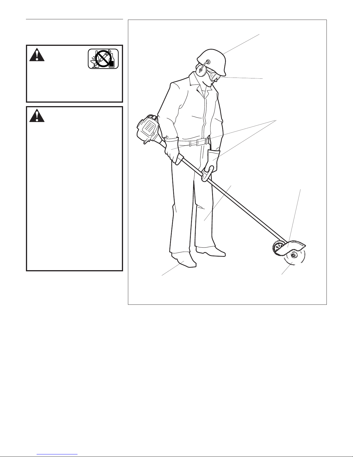
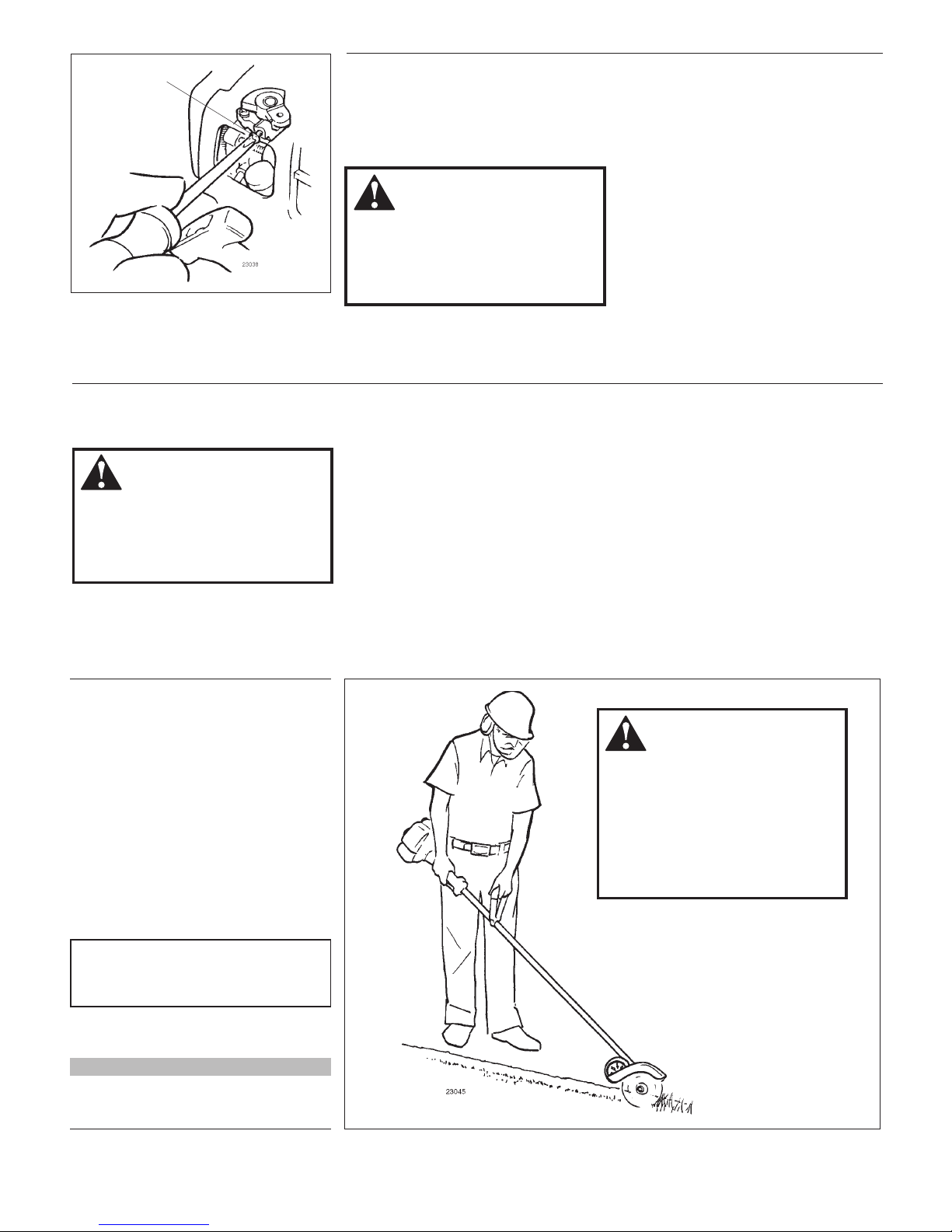
Work Safely
Lawn Edgers operate at very high speeds
and can do serious damage or injury if
they are misused or abused. Never allow
a person without training or instruction to
operate this unit!
WARNING!
Use Good Judgment
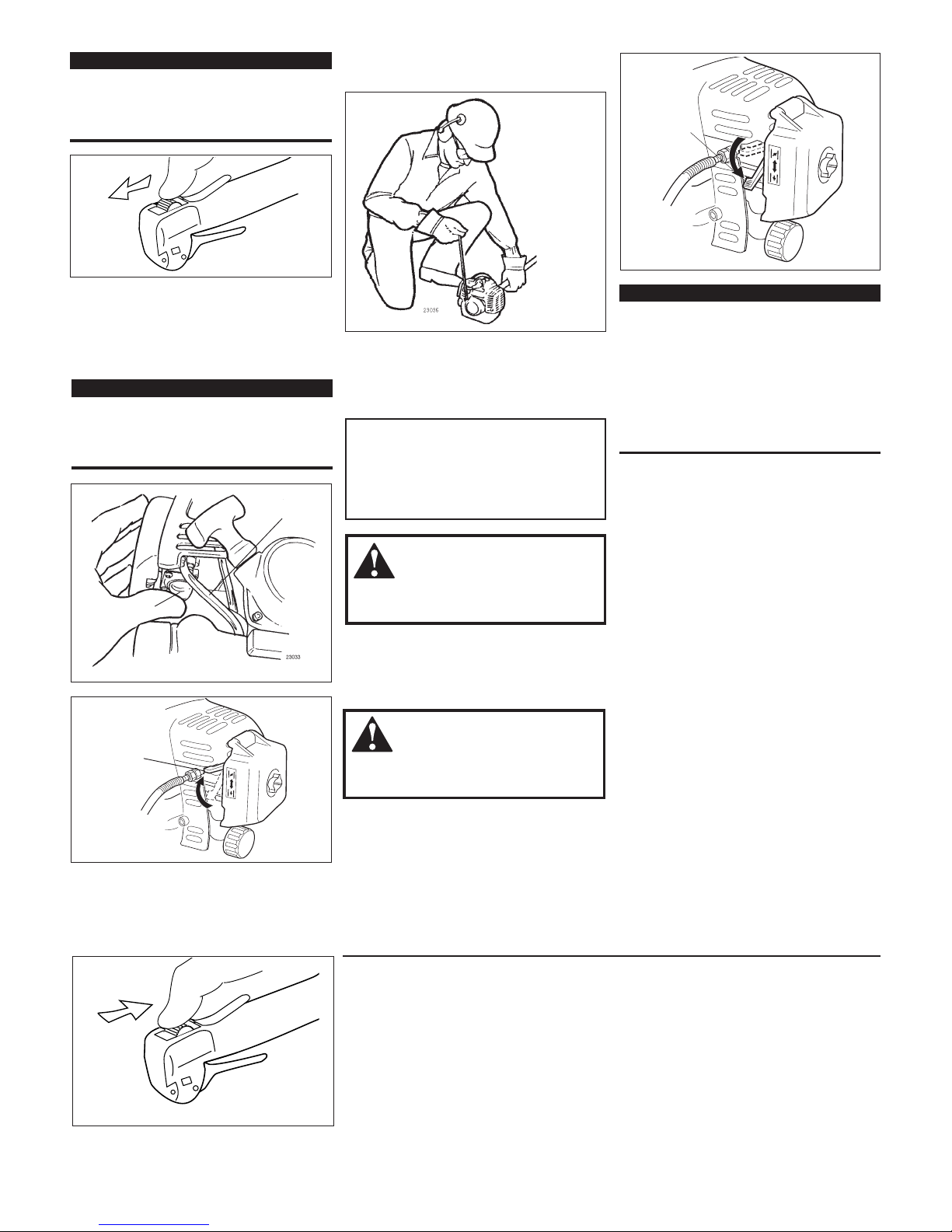
NEVER run the engine when transport-
ing the unit.
NEVER run the engine indoors! Make
sure there is always good ventilation.
Fumes from engine exhaust can cause
serious injury or death.
ALWAYS stop the unit immediately if
it suddenly begins to vibrate or shake.
Inspect for broken, missing or improp-
erly installed parts or attachments.
ALWAYS keep the unit as clean as
practical. Keep it free of loose vegeta-
tion, mud, etc.
ALWAYS hold the unit firmly with both
hands when cutting or trimming, and
maintain control at all times.
ALWAYS keep the handles clean.
ALWAYS disconnect the spark plug
wire before performing any
maintenance work.
WARNING!
Never make unauthorized attachment
installations.
WARNING!
The engine exhaust from this product
contains chemicals known to the State
of California to cause cancer, birth
defects or other reproductive harm.
Throughout this manual are special
“Attention Statements.”
WARNING!
A statement preceded by the trian-
gular attention symbol and the word
“WARNING” contains information that
should be acted upon to prevent seri-
ous bodily injury.
CAUTION!
A statement preceded by the word
“CAUTION” contains information that
should be acted upon to prevent me-
chanical damage.
IMPORTANT!
A statement preceded by the word
“IMPORTANT” is one that possesses
special significance.
NOTE:
A statement preceded by the word “NOTE”
contains information that is handy to know
and may make your job easier.
Attention Statements
IMPORTANT!
The operational procedures described in
this manual are intended to help you get
the most from unit as well as to protect
you and others from harm. These proce-
dures are guidelines for safe operation un-
der most conditions, and are not intended
to replace any safety rules and/or laws
that may be in force in your area. If you
have questions regarding your Shindaiwa
power tool, or if you do not understand
something in this manual, your Shindaiwa
dealer will be glad to assist you. You may
also contact Shindaiwa, Inc. at the ad-
dress printed on the back of this manual.


 Instruction Manual")


