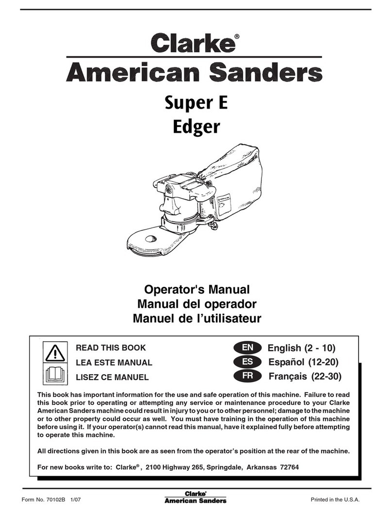
Clarke Super E User manual

Electronic Service
Manuals
This electronic document is provided as a service to our customers.
Wedonotcreatethecontentsoftheinformationcontainedinthisdocu-
ment. Shouldyouhavedetailedquestionspertainingtotheinformation
contained in this document, you may contact Michco, or the manufac-
turer which provided the original information in this electronic deliver-
able. Michco’sonlypartin this electronic deliverable was the electronic
assemblyprocess. Byprovidingthismanualonlinewearenotguaran-
teeing parts availability.
You may contact Michco through the following methods:
Phone (517) 484-9312 or (800) 331-3339
2011 N. High St. -- Lansing, Michigan -- 48906
Fax: (517) 484-9836
Email: [email protected]
Web site: www.Michco.Com
Parts Web site: www.FloorMachineParts.Com
Order Parts on Line at:
www.FloorMachineParts.Com
Directly to Parts & Service:
By Fax: (517) 702-2041
By Voice: Use numbers above.
Serving the Cleaning Industry Since 1922
Notice: All copyrighted material remains property of original owners, all trademarks are property of respective owners.
ManualsaresubjecttoManufacturer’sreproductionlimitations. Originalsorreproductionswereprovidedbymanufacturers
through a request. We make no warranty as to the correctness of information provided in this document and you assume
allrisk. By placing thesemanualsonlinewe are notdeclaringourcorporation to be anmanufacturerauthorizeddealer or
provider, please check ourwebsiteforauthorizedmanufacturerswerepresent.

Form No. 70102B 1/07 revised 4/10
Super E
Edger
READ THIS BOOK
LEA ESTE MANUAL
LISEZ CE MANUEL
LESEN SIE DIESES HANDBUCH
IMPORTANTE
ПРОЧИТАЙТЕ ЭТО РУКОВОДСТВО
English (2 - 10)
Español (12-20)
Français (22-30)
Deutsch (32-41)
Italiano (42-51)
Русский (52-60)
ES
EN
FR
Operator's Manual / Manual del operador / Manuel de l’utilisateur
Bedienungshandbuch / Manuale per l’operatore / Руководство по эксплуатации
Models: 07068C, 07074C, 07153A, 07130A, 07131A
DE
IT
RU

EN
ENGLISH
-2- FORM NO. 70102B Clarke®American Sanders Operator's Manual (EN) - Super E
Contents of this Book
Operator Safety Instructions............................................................................... 3
Machine Specifications....................................................................................... 5
Sanding Cuts and Sandpaper .......................................................................... 6
Machine Set-Up.................................................................................................. 7
Operating Instructions ........................................................................................ 8
Adjustment Procedures ...................................................................................... 9
Routine Maintenance ....................................................................................... 10
Section II Parts and Service Manual
AssemblyDrawing #1....................................................................................... 62
Assembly Parts List #1 .................................................................................... 63
Assembly Drawing #2....................................................................................... 64
Assembly Parts List #2..................................................................................... 65
Wiring Diagram................................................................................................. 66
READ THIS BOOK
This book has important information for the use and safe operation of this machine. Failure to
read this book prior to operating or attempting any service or maintenance procedure to your
Clarke American Sanders machine could result in injury to you or to other personnel; damage to
the machine or to other property could occur as well. You must have training in the operation of
this machine before using it. If operator(s) cannot read English, have this manual explained fully
before attempting to operate this machine.
All directions given in this book are as seen from the operator’s position at the rear of the ma-
chine.
WARNING!
The Products sold with this Manual contain or may contain chemicals that are known to certain governments (such as the State of
California, as identified in its Proposition 65 Regulatory Warning Law) to cause cancer, birth defects or other reproductive harm. In
certain locations (including the State of California) purchasers of these Products that place them in service at an employment job site
or a publicly accessible space are required by regulation to make certain notices, warnings or disclosures regarding the chemicals
that are or may be contained in the Products at or about such work sites. It is the purchaser’s responsibility to know the content of,
and to comply with, any laws and regulations relating to the use of these Products in such environments. The Manufacturer disclaims
any responsibility to advise purchasers of any specific requirements that may be applicable to the use of the Products in such environ-
ments.
revised 4/10

EN
ENGLISH
Clarke®American Sanders Operator's Manual (EN) - Super E FORM NO. 70102B - 3 -
DANGER means: Severe bodily injury or death can occur to you or other personnel if the
DANGER statements found on this machine or in this Operator's Manual are
ignored or are not adhered to. Read and observe all DANGER statements
found in this Operator's Manual and on your machine.
WARNING means: Injury can occur to you or to other personnel if the WARNING statements
found on your machine or in this Operator's Manual are ignored or are not
adhered to. Read and observe all WARNING statements found in this
Operator's Manual and on your machine.
CAUTION means: Damage can occur to the machine or to other property if the CAUTION state-
ments found on your machine or in this Operator's Manual are ignored or are
not adhered to. Read and observe all CAUTION statements found in this
Operator's Manual and on your machine.
DANGER: Failure to read the Operator's Manual before operating or servicing this sanding equip-
ment could result in injury to the operator or to bystanders and could cause damage to
the equipment. Read and observe all safety statements found in this manual and on the
sanding equipment. Make sure all labels, decals, warnings, cautions and instructions are
fastened to the equipment. Replace any that are damaged or missing. You must have
training in the operation of this equipment before using it. If the operator is unable to
read this manual, have it explained fully before they attempt to use this equipment.
DANGER: Sanding/finishing wood floors can create an environment that can be explosive. The fol-
lowing safety procedures must be adhered to:
• Cigarette lighters, pilot lights and any other source of ignition can create an explosion
when active during a sanding session. All sources of ignition should be extinguished
or removed entirely if possible from the work area.
• Work areas that are poorly ventilated can create an explosive environment when
certain combustible materials are in the atmosphere, i.e., solvents, thinners, alcohol,
fuels, certain finishes, wood dust and other combustible materials. Floor sanding
equipment can cause flammable material and vapors to burn. Read the manufactur-
er's label on all chemicals used to determine combustibility. Keep the work area well
ventilated.
• Spontaneous combustion or an explosion can occur when working with sanding dust.
The sanding dust can self-ignite and cause injury or damage. Sanding dust should
be disposed of properly. Always empty the sanding dust into a metal container that is
located outside of any building(s).
• Remove the contents of the dust bag when the bag is 1/3 full. Remove the contents of
the dust bag each time you finish using the equipment. Never leave a dust bag unat-
tended with sanding dust in it.
• Do not empty the contents of the dust bag into a fire.
• Hitting a nail while sanding can cause sparks and create an explosion or fire. Always
use a hammer and punch to countersink all nails before sanding floors.
OPERATOR SAFETY INSTRUCTIONS
WARNING AVERTISSEMENT ADVERTENCIA


EN
ENGLISH
-4- FORM NO. 70102B Clarke®American Sanders Operator's Manual (EN) - Super E
DANGER: Operating partially assembled sanding equipment could result in injury to the operator or by-
stander and could cause damage to the equipment or to other property.
• Do not operate this equipment unless it it fully assembled and all guards, doors and covers
are secured.
• Keep all fasteners tight.
• Keep all adjustments within manufacturers specifications.
DANGER: Moving parts on this sanding equipment can cause injury to the operator or bystanders.
• Keep hands, feet and loose clothing away from all moving parts.
• Do not change or adjust the abrasive while the sanding equipment is running.
• Do not service the sanding equipment while it is running.
DANGER: This sanding equipment requires a supply of electricity. Improper use could result in electrical
shock or fire.
• Connect only to an electrical source matching what is shown on the equipment nameplate.
• Do not use this sanding equipment on an ungrounded electrical circuit. Consult an electri-
cian if you suspect the circuit is not properly grounded.
• Do not use this sanding equipment with a damaged electrical cord. Inspect before each
use.
• Avoid striking the elelctrical cord with the abrasive. Always lift the electrical cord over the
sanding equipment.
• Do not use the electrical cord to move the sanding equipment.
• Disconnect the electrical source before servicing this equipment.
WARNING: Injury to the operator or bystander can occur if protective gear is not worn while sanding. Always
use eye, ear, and respiratory protection while performing any sanding operation.
WARNING: Bodily injury could occur if power is applied to the equipment with the power switch already in
the "ON" position. Always check to assure that the power switch is in the "OFF" position before
connecting power supply.
CAUTION: Maintenance and repairs performed by unauthorized personnel could result in damage or injury.
Maintenance and repairs performed by unauthorized personnel will void your warranty. Servicing
of this unit must always be referred to an authorized Clarke American Sanders distributor.
CAUTION: Use of this equipment to move other objects or to climb on could result in injury or damage. Do
not use this equipment as a step or furniture. Do not ride on this equipment.
CAUTION: Damage could occur to the equipment if not properly kept in a dry building for storage. Store
the equipment in a dry building.
CAUTION: Serious damage to the floor can occur if the sanding equipment is left running in one spot while
the sanding disc is in contact with the floor. To avoid damage to the floor, do not dwell while
lowering or raising the sanding disc. Always sand with a constant motion.

EN
ENGLISH
Clarke®American Sanders Operator's Manual (EN) - Super E FORM NO. 70102B - 5 -
Available Attachments
Part # Description Disc Dia. Effective Reach Disc Rate
16529A Extension Kick Toe 7 inch 5-1/2 inches 2800 RPM
w/ 7" pad
16528A Extension Kick Toe 5 inch 6 7/8inches 3200 RPM
w/ 5" pad
13706A Extension 13" 5 inch 13 inches 3200 RPM
13708A Extension Picket 3 inch 47/8inches 5900 RPM
10019C Extension Picket 3 inch 47/8inches 5900 RPM
w/1/4 turn
Specifications
Model 07068C 07074C 07153A 07130A/07131A
Electrical 115V~, 60 Hz 230V~, 50 Hz 115V~, 50 Hz 230V~, 50Hz
Requirements 12.0 A, 1.3 kW 6.0 A, 1.3 kW 12.0 A, 1.3 kW 6.0 A, 1.3 kW
Sound Emmission (Lpm) 96 dBA 96 dB(A) 96 dB(A) 96 dB(A)
Vibration 3.6 m/s2 3.6 m/s2 3.6 m/s2 3.6 m/s2
Motor Series Series Series Series
Universal Universal Universal Universal
Electrical Cable 50', 14-3 SO 50', 14-3 SJT HO7VV 3 x 1.5mm2
5-15P Plug AU2-15P Plug CEE 7/7 Plug
Drive System 5mm Precision 5mm Precision 5mm Precision 5mm Precision
Joined Belt Joined Belt Joined Belt Joined Belt
Fan Flow Rate 110 CFM 110 CFM 43 liter/s 43 liters/s
Weight 32 lbs. 32 lbs. 14.5 kg 14.5 KG
Height 11 in. 11 in. 28 cm. 28 cm
Super E
Specifications

EN
ENGLISH
-6- FORM NO. 70102B Clarke®American Sanders Operator's Manual (EN) - Super E
12 grit For removing gross imperfections and
16 grit restore evenness to old flooring. To remove
20 grit build-up of paints and varnishes.
24 grit
30 grit For first sanding of new flooring (maple, oak).
36 grit For removing minor imperfections and finishes
from old flooring.
40 grit For initial cut on new flooring (oak, walnut).
For removing minor imperfections and finishes
from old flooring.
50 grit For first sanding of new flooring (cedar, pine,
fir) For clean-up of 16 grit.
60 grit For clean-up from initial cut 36 grit.
80 grit For final sanding of certain hardwoods. For
clean-up of initial cuts (50 grit).
100 grit For final sanding of certain hardwoods and
conifers where a smooth surface is desired.
120 grit For final sanding of certain conifers.
150 grit For final sanding of certain conifers where a
smooth surface is desired for surface
roughening between coats of finish.
SANDING CUTS AND SANDPAPER
Initial Cut
The purpose of the initial cut is to remove old finish and gross imperfections on the floor surface. A coarse abrasive should be used.
If glazing, loading, or burning takes place immediately into an initial cut, select a coarser abrasive. If this should occur during an
initial cut, the abrasive has dulled and must be replaced.
Final Cuts
The purpose of a finishing cut is to remove the scratches produced during the initial cut. Use a fine (60 - 80 grit) grain abrasive.
If the surface remains rough after a finishing cut, it may be necessary to use an even finer grain of abrasive (80 - 100 grit). Care
should be taken in selecting the grit size of the abrasive. A very fine grain will close the pores on a wood floor making admission of
a stain difficult.
Grain Use
Standard Grade
Part #/Qty
Professional Grade
Part #/Qty
Standard Grade
Part #/Qty
Professional Grade
Part #/Qty
7" Diameter 7" Diameter 5" Diameter 5" Diameter
945314/50
945315/50
945316/50
94319/100
94321/100
945322/100
945323/100
945324/100
945701/250
945702/250
945703/250
945704/500
945705/500
945706/500
945707/500
945708/500
945709/500
945710/500
945594/200
945595/200
945596/200
945597/300
945598/300
945599/300
945600/300
945601/300
945602/300
945603/300
945604/300
945605/500
945606/300
945300/50
945301/50
945302/50
945305/100
945307/100
945308/100
945309/100
945310/100

EN
ENGLISH
Clarke®American Sanders Operator's Manual (EN) - Super E FORM NO. 70102B - 7 -
Figure 1
Figure 2
MACHINE SET-UP
This sanding machine is designed to be operated with a
remote vacuum dust collection system or with the included
dust bag.
Preparing Remote Vacuum Dust Collection Systems
To prepare the machine for remote vacuum dust collection
systems that have a 2" hose end, follow this procedure:
1. Install 2" hose end (figure 1, A) directly over the ex-
haust tube (figure 1, B).
2. The exhaust tube can be rotated for optimum conve-
nience.
To prepare the machine for remote vacuum dust collection
systems that have a 1 ½" hose end, follow this procedure:
1. Install the 2" x 1½" hose end adaptor (Part No.
30563A) (figure 1, C) over the exhaust tube (figure 1,
B).
2. Insert 1 ½" hose end (figure 1, D) into the adaptor
(figure 1, C).
NOTE: Start the remote vacuum collection system
before operation.
Preparing to use the included dust bag
To prepare the machine for use with the included dust bag
(Part No. 53544B), follow this procedure:
1. Install the dust bag by pressing the end onto the ex-
haust tube until the ring locks into the groove (figure
2). This is best done by pressing on the back of the
bag opening with the palm of your hand.
2. The exhaust tube can be rotated for optimum conve-
nience.
3. To remove the dust bag from the exhaust tube, pry
up the end of the bag opening to partially release the
internal rib from the groove, then pull.
4. To empty the dust bag, unzip the disposal flap and
force contents out by inverting the bag.
NOTE: For best results, empty frequently. Follow all
warnings posted in this manual and on the dust bag.
Install the dust bag by
pressing the end onto the
exhaust tube until the ring
locks into the groove.
A
2" Hose from
vacuum system
(not included)
1.5" Hose from
vacuum system
(not included)
D
B
C
Exhaust Tube
(30563A) 2" Tube x 1.5" hose
adaptor

EN
ENGLISH
-8- FORM NO. 70102B Clarke®American Sanders Operator's Manual (EN) - Super E
MACHINE SET-UP
Preparing the machine for operation
1. Familiarize yourself with the machine. Read all danger,
warning, and caution statements and the Owner's Manual
before operating this machine. If you or your operator cannot
read English, have this manual explained fully before at-
tempting to operate this machine.
2. Remove belt guard (figure 3-a). Position extension over
motor and start thumb screw (figure 3-b). Position drive
belt in lower most set of grooves on motor
pulley as shown in figure 4-a (for the kick-toe
extension with 7" dia. pad.) The upper most set of
grooves are reserved for use with all other attachments. Ten-
sion drive belt, then tighten thumb screws. Rotate pad driver
to inspect position of drive belt in motor pulley and pad driver
belt grooves.
CAUTION: Rapid belt wear will occur if both strands of
the drive belt do not run in their respective
grooves on the pad driver and motor pulley.
3. Install belt guard.
4. Remove screw and abrasive retainer. Center abrasive on
pad and secure with abrasive retainer and screw. (Figure
4-b)
5. Return machine to upright position and tilt machine back
on casters until it comes to rest on the exhaust bracket.
Machine will be in a reclined position. Do not allow machine
to rest on pad especially after use, or compression set may
take place within elastomer on pad. This will create a flat
spot and bounce during use.
Figure 3
Figure 4
1. Move machine to the location of your work. Set any exposed nails
with hammer and punch to avoid encounter with abrasive. Connect
the supply cable to an appropriately grounded and fused circuit.
WARNING: Bodilyinjurycouldoccurifpowerisapplied tothemachine
with the control switch in the "ON" position. Always verify
that the control switch is in the "OFF" position before
connecting to the power cable.
OPERATING INSTRUCTIONS

EN
ENGLISH
Clarke®American Sanders Operator's Manual (EN) - Super E FORM NO. 70102B - 9 -
OPERATING INSTRUCTIONS
2. Make sure the control switch is set to "OFF". For the "OFF" position,
the switch is actuated towards the operator. See the markings on the
switch. Connect the supply cable to the motor electric cable. (Figure
5)
3. With the machine in the reclined position firmly grasp both handles
and activate the control switch "ON".
4. Gradually lower pad to surface intended for sanding. Make sure the
machine is in motion while the pad is engaged with the surface to be
sanded. You may use broad circular motion as you sand along the
length of the surface or your may use a combination of forward and
sideward motions. In time you will develop your own technique to
optimize coverage and dust recovery. It is advisable to not add effort
to the pad as this may lead to "nosing in" or "tipping" which produces
grooves or lines on the surface.
5. When replacing abrasive, emptying the contents of the dust bag, or
sanding operation is completed, return machine to reclined position,
deactivate the control switch to "OFF" then disconnect the motor
electric cable from the supply cable.
6. Empty dust bag whenever it becomes 1/3 full.
DANGER: Failure to disconnect the supply cable from machine
whenever servicing, replacing abrasive, or emptying the
dust bag could result in electrocution or severe injury.
Never leave machine unattended while the supply cable
is connected.
DANGER: Never leave dust bag unattended with sanding dust in it.
Sanding dust can self ignite and cause a fire or explo-
sion. Empty dust bag into a metal container, clear of any
combustibles. Do not empty content into a fire. Do not
overfill dust bag.
ADJUSTMENT PROCEDURES
Leveling
To level machine: Place screwdriver in slot on caster stem to prevent rotation.
Use a 3/4 wrench to loosen locknut (see Figure 6).
Condition - Pad creates ridges on both edges or a "hop" is experienced:
Rotate both stems equal amounts clockwise. Tighten locknuts and test on a
piece of plywood. Repeat procedure until condition is corrected. We recom-
mend you not exceed 1/8" rotation for each attempt.
Condition - Pad creates a ridge on the tip of the pad: Rotate both stems
counter clockwise, tighten locknuts and test. Repeat procedure until condition
is corrected. Use only 1/8 rotation for each attempt.
Condition - Pad creates a ridge on only one side of the pad: Either rotate the
stem of the side effected clockwise or rotate the stem opposite conterclock-
wise, depending on whether the ridge terminates beyond the tip of the pad or
prior to it. If it is prior to the tip, adjust the side effected, otherwise adjust the
opposite side.
Belt Tension
The design of the belt allows it to deliver the power with very little tenstion.
The tension should be great enough to prevent slippage and wear. Excessive
tension will only shorten bearing and belt life.
Figure 6
Figure 5

EN
ENGLISH
-10- FORM NO. 70102B Clarke®American Sanders Operator's Manual (EN) - Super E
ROUTINE MAINTENANCE
Carbon Brushes
Inspect all four brushes every 6 months or 250 hours. Access to the
brushes is gained through the front and back motor vent plugs and under
both covers. Press tab on spring clip assembly in, rotate, then remove
(figure 7). Use needlenose pliers to disconnect the shunt wire. If any
brush has worn to 3/8" in length or shorter, replace the entire set.
CAUTION: Use only motor brush part no. 40818A
or 40055A with shunt wire or motor failure will occur.
When replacing the brushes, make sure that the brush seats against the
commutator, the tab on the spring clip assembly is fully seated in pocket,
and the brush is free to travel. When returning the switch covers, keep all
wires clear of the commutator and any pinch sites.
Pad
In time the elastomer on the pad may wear or become damaged. To re-
place, remove pad by placing screwdriver in slot of shaft, grasp pad and
rotate shaft counterclockwise. Remove existing elastomer and clean hub
throughly to remove old adhesive. Roughen surface of new elastomer to
provide good bond sights. Apply a good rubber cement to both surfaces
and allow to tack. 3M# 1300 rubber and gasket cement is a suitable
choice. Apply elastomer to hub and knead throughly. Apply pressure to
elastomer and allow to stand over night. Apply a medium strength thread
locker to the external threaded end of the shaft. Install belt in grooves
on hub and screw down on shaft. Install abrasive retainer on to shaft.
Locate a flat surface and tape 80 grit abrasive to surface. Using machine
"dress in" by sanding the elastomer on the pad. Continue sanding until
the entire surface of the elastomer shows signs of sanding. As in opera-
tion of the machine, take precautions performing this procedure.
Pad Driver
Periodically inspect belt grooves on pad driver for an accumulation of
paint or varnish especially after jobs where several layers of paint or
varnish have been removed. Particles of paint or varnish can deposit in
the grooves, creating vibration and damaging the drive belt. Use a plastic
putty knife or similar object to remove the deposits.
Dust Bag
Periodically the dust bag should be turned inside out, shaken vigorously
and machine washed in cold water to prevent pore blockage and loss of
dust control.
Bearings
To insure reliable performance, armature and pad driver bearings should
be inspected for wear or damage after 1500 hours. If used heavily the
bearings should be replaced seasonally.
Figure 7

EN
ENGLISH
Clarke®American Sanders Operator's Manual (EN) - Super E FORM NO. 70102B - 11 -

-12- FORM NO. 70102B Clarke®American Sanders Manual del operador (ES) - Super E
ES
ESPAÑOL
Instrucciones de seguridad para el operador ............................ 13
Introducción y especificaciones de la máquina ......................... 15
Cortes de lija y papel de lija...................................................... 16
Instalación de la máquina.......................................................... 17
Operación de la máquina .......................................................... 18
Procedimientos de ajuste de la lijadora..................................... 19
Mantenimiento de rutina............................................................ 20
Sección II Repuestos y manual de servicio
Plano de montaje #1 ................................................................ 62
Listado de piezas de montaje #1 ...............................................63
Plano de montaje #2 ................................................................. 64
Listado de piezas de montaje #2 .............................................. 65
Plano de cableado.......................................................................66
LEA ESTE MANUAL
Este manual contiene información importante acerca del uso y la seguridad de la máquina. Si no lee el
manual antes de utilizar su máquina Clarke American Sanders o de intentar realizar los procedimientos
de reparación o mantenimiento de la misma, usted o el resto del personal podrían sufrir lesiones; asi-
mismo, podrían producirse daños a la máquina o a otras propiedades. Antes de utilizar la máquina, es
necesario recibir la capacitación adecuada en la operación de la misma. Si el operador de la máquina
no sabe leer en español, explíquele el manual exhaustivamente antes de que intente utilizarla.
Todas las indicaciones incluidas en este manual se ofrecen desde la posición del operador en la parte
posterior de la máquina.
revised 4/10
ADVERTENCIA:
Los Productos a la venta en este Manual contienen, o pueden contener, productos químicos reconocidos por algunos gobiernos
(como el Estado de California, según lo indica en su Proposición 65, Ley de Advertencia Regulatoria) como causantes de cáncer,
defectos de nacimiento u otros daños reproductivos. En algunas jurisdicciones (incluido el Estado de California), los compradores de
estos Productos que los coloquen en servicio en un emplazamiento laboral o en un espacio de acceso público tienen la obligación
regulatoria de realizar determinados avisos, advertencias o divulgaciones respecto de los productos químicos contenidos o posi-
blemente contenidos en los Productos utilizados en tal lugar. Es la responsabilidad del comprador conocer y cumplir con todas las
leyes y reglamentaciones relacionadas con el uso de estos Productos en tales entornos. El Fabricante niega toda responsabilidad de
informar a los compradores sobre requisitos específicos que pueden regir el uso de los Productos en tales entornos.

Clarke®American Sanders Manual del operador (ES) - Super E FORM NO. 70102B - 13 -
ES
ESPAÑOL
PELIGRO significa: Usted u otras personas pueden estar expuestos a sufrir lesiones personales,
inclusive la muerte si las indicaciones de PELIGRO que se encuentran en
esta máquina o en el manual de instrucciones se ignoran o no se tienen en
cuenta. Lea y respete todas las indicaciones de PELIGRO que se encuen-
tran en el manual de instrucciones y en la máquina.
ADVERTENCIA significa: Usted u otras personas pueden estar expuestos a sufrir lesiones per-

sonales, si las indicaciones de ADVERTENCIA que se encuentran en esta

máquina o en el manual de instrucciones se ignoran o no se tienen en
cuenta. Lea y respete todas las indicaciones de ADVERTENCIA que se
encuentran en
el manual de instrucciones y en su máquina.
PRECAUCIÓN significa: La máquina u otros bienes pueden sufrir daños materiales si las indica-
ciones de PRECAUCIÓN que se encuentran en la máquina o en el manual
de instrucciones se ignoran o no se tienen en cuenta. Lea y respete todas
las indicaciones de PRECAUCIÓN que se encuentran en el manual de in-
strucciones y en la máquina.
PELIGRO: En caso de que no se lea el manual de instrucciones antes de operar este equipo de
lijado o realizar el mantenimiento del mismo podría resultar en que el operador u otras
personas en el área sufriesen lesiones personales y el equipo podría sufrir daños ma-
teriales. Lea y respete todas las indicaciones de seguridad que se encuentran en este
manual y en el equipo de lijado. Asegúrese que todas las etiquetas, calcomanías, adver-
tencias, precauciones e instrucciones estén adheridas a la máquina. Reemplace cual-
quier indicación que esté dañada o falte. Antes de utilizar el equipo, es necesario recibir
la capacitación adecuada en la operación del mismo. Si el operador no puede leer
este manual, explíqueselo exhaustivamente antes que intente utilizar este equipo.
PELIGRO: El lijado/acabado de pisos de madera puede crear un entorno que puede ser explosivo.
Se deberán tener en cuenta los siguientes procedimientos de seguridad:
• Los encendedores, las lámparas indicadoras y cualquier otra fuente de ignición
pueden provocar una explosión si se activan durante una sesión de lijado. Si es po-
sible, apague o retire por completo todas las fuentes de ignición del área de trabajo.
• Las áreas de trabajo que estén muy poco ventiladas pueden crear un entorno explo-
sivo cuando se encuentran determinados materiales combustibles en la atmósfera: por
ejemplo, solventes, diluyentes, alcoholes, combustibles, ciertos acabados, polvo de
madera y otros materiales combustibles. El equipo de lijado de pisos puede provocar
la combustión de los materiales y vapores inflamables . Lea la etiqueta del fabricante
sobre todas las sustancias químicas utilizadas para determinar su combustibilidad.
Mantenga el área de trabajo bien ventilada.
• Pueden producirse una combustión espontánea o una explosión cuando se trabaja
con polvo de lijado. El polvo de lijado puede auto-encenderse, provocando lesiones
personales y daños materiales. Deshágase del polvo de lijado de una manera ad-
ecuada. Vacíe siempre el polvo de lijado dentro de un recipiente de metal que esté
localizado fuera del edificio.
• Extraiga el contenido de la bolsa de polvo cuando la misma esté llena a 1/3. Extraiga
el contenido de la bolsa de polvo cada vez que termine de usar el equipo. Nunca deje
la bolsa sin vigilancia cuando haya polvo de lijado en la misma.
• No vacíe el contenido de la bolsa de polvo en el fuego.
• Golpear un clavo cuando se lija puede causar chispas y crear una explosión o un
incendio. Utilice siempre un martillo y perfore para avellanar todos los clavos antes de
lijar los pisos.
INSTRUCCIONES DE SEGURIDAD PARA EL OPERADOR

-14- FORM NO. 70102B Clarke®American Sanders Manual del operador (ES) - Super E
ES
ESPAÑOL
PELIGRO: La operación de equipo de lijado parcialmente ensamblado podría provocar que el operador o las
personas en el área de trabajo sufriesen lesiones, y también podría causar daños materiales al
equipo o a otro bienes.
• No opere este equipo a menos que esté totalmente ensamblado y que todas las protecciones,
puertas y tapas estén bien aseguradas en su lugar.
• Mantenga todas las sujeciones apretadas.
• Mantenga todos los ajustes dentro de las especificaciones del fabricante.
PELIGRO: Las partes móviles de este equipo de lijado pueden causar lesiones al operador o a las personas que
se encuentren en el área de trabajo.
• Mantenga las manos, los pies y la vestimenta suelta alejados de todas las partes móviles.
• No cambie ni ajuste el abrasivo mientras el equipo de lijado esté en funcionamiento.
• No realice ningún servicio de reparación o mantenimiento al equipo de lijado mientras esté en
funcionamiento.
PELIGRO: Este equipo de lijado requiere un suministro de electricidad. El uso inadecuado podría provocar una
descarga eléctrica o un incendio.
• Conecte únicamente a un suministro eléctrico que coincida con lo que se muestra en la placa de
identificación del equipo.
• No utilice este equipo de lijado sobre un circuito eléctrico sin conexión a tierra. Consulte con un
electricista si sospecha que el circuito no está adecuadamente conectado a tierra.
• No utilice este equipo de lijado con un cable eléctrico dañado. Inspecciones antes de cada uso.
• Evite golpear el cable eléctrico con el abrasivo. Eleve siempre el cable eléctrico sobre el equipo
de lijado.
• No utilice el cable eléctrico para mover el equipo.
• Desconecte el suministro eléctrico antes de realizar un servicio de reparación o mantenimiento
al equipo.
ADVERTENCIA: Si no se utilizan los dispositivos de protección personal correctos mientras se realiza el lijado, el
operador o cualquier persona en el área de trabajo pueden sufrir lesiones. Utilice siempre protección
respiratoria, ocular y auditiva mientras realice una operación de lijado.
ADVERTENCIA: Pueden producirse lesiones personales si se aplica potencia al equipo con el interruptor de aliment-
ación ya situado en la posición “ON” (Encendido). Asegúrsese siempre de que el interruptor de
alimentación esté en la posición “OFF” (Apagado) antes de conectar la fuente de alimentación.
PRECAUCIÓN: El mantenimiento y las reparaciones realizados por personal no autorizado podrían producir daños
materiales o lesiones personales. El mantenimiento y las reparaciones realizadas por personal no
autorizado anularán su garantía. El mantenimiento y las reparaciones de esta unidad siempre deben
ser realizados por un distribuidor autorizado de Clarke American Sanders.
PRECAUCIÓN: Si utiliza este equipo para desplazar otros objetos o para subirse al mismo se pueden producir lesiones
o daños. No utilice este equipo como escalera ni como mueble. No se suba al equipo.
PRECAUCIÓN: Si el equipo no se guarda correctamente en un edificio sin humedad podría resultar dañado. Guarde
el equipo en un lugar seco.
PRECAUCIÓN:Se puede causar un daño grave al piso si el equipo de lijado se deja funcionando en un lugar mientras
el disco de lijado está en contacto con el piso. Para evitar que se dañe el piso, cuando baje o eleve
el disco de lijado, hágalo en el menor tiempo posible. Siempre lije con un movimiento constante.

Clarke®American Sanders Manual del operador (ES) - Super E FORM NO. 70102B - 15 -
ES
ESPAÑOL
Accesorios disponibles
Diámetro Velocidad
Pieza # Descripción del disco Alcance efectivo del disco
16529A Extensión para 7 pulgadas 5½ pulgadas 2800 RPM
terminaciones de
bases de muebles
(kick toe) con
almohadilla de 7 pulgadas
16528A Extensión para 5 pulgadas 6 7/8 pulgadas 3200 RPM
terminaciones de
bases de muebles
(kick toe) con
almohadilla de 5 pulgadas
13706A Extensión de 13 5 pulgadas 13 pulgadas 3200 RPM
pulgadas
13708A Extensión para 3 pulgadas 47/8 pulgadas 5900 RPM
balaustradas de
peldaños
10019C Extensión para
balaustradas de
peldaños w/1/4 turn 3 pulgadas 47/8 pulgadas 5900 RPM
Especificaciones
Modelo 07068C 07074C 07153A 07130A/07131A
Requerimientos 115V~, 60 Hz 230V~, 50 Hz 115V~, 50 Hz 230V~, 50Hz
Eléctricos 12.0 A, 1.3 kW 6.0 A, 1.3 kW 12.0 A, 1.3 kW 6.0 A, 1.3 kW
Emisión de sonido (Lpm) 96 dBA 96 dB(A) 96 dB(A) 96 dB(A)
Vibración 3.6 m/s2 3.6 m/s2 3.6 m/s2 3.6 m/s2
Motor Serie Serie Serie Serie
Universal Universal Universal Universal
Cable Eléctrico 50', 14-3 SO 50', 14-3 SJT HO7VV 3 x 1.5mm2
5-15P Enchufe
AU2-15P Enchufe
CEE 7/7 Enchufe
Sistema de impulsión Precisión 5mm Precisión 5mm Precisión 5mm Precisión 5mm
Correa articulada Correa articulada Correa articulada Correa articulada
Tasa de flujo de
ventilación 110 CFM 110 CFM 43 litros/s. 43 litros/s.
Peso 14.5 kg 14.5 kg 14.5 kg 14.5 KG
Altura 28 cm 28 cm 28 cm. 28 cm
Model Super E Edger
Especificaciones

-16- FORM NO. 70102B Clarke®American Sanders Manual del operador (ES) - Super E
ES
ESPAÑOL
Cortes de lija y papel de lija
Corte inicial
El propósito del corte inicial es sacar el acabado viejo y las imperfecciones mayores de la superficie del piso.
Se debe usar un abrasivo grueso.
Si un corte inicial aparece inmediatamente glaseado, cargado o quemado, seleccione un abrasivo más
grueso. Si esto ocurriera durante un corte inicial significa que el abrasivo se ha desgastado y deberá ser
reemplazado.
Cortes finales
El propósito de un corte de acabado es eliminar los rayones producidos durante el corte inicial. Utilice un
abrasivo de grano fino (60- 80 granos) .
Si la superficie permanece áspera después de un corte de acabado, puede ser necesario utilizar un abrasivo
de grano aún más fino (80 - 100 granos). Se deberá tener cuidado al seleccionar el tamaño del grano del
abrasivo. Un grano muy fino cerrará los poros sobre el piso de madera dando lugar a problema de man-
chas.
12 granos Para eliminar imperfecciones mayores y
16 granos restaurar la uniformidad a los pisos viejos.
20 granos Para eliminar la acumlación de pinturas y
24 granos barnices.
30 granos Para el primer lijado de pisos nuevos (arce,
36 granos roble). Para eliminar imperfecciones menores
y acabados de pisos viejos.
40 granos Para el primer lijado de pisos nuevos (roble,
nogal). Para eliminar imperfecciones menores
y acabados de pisos viejos.
50 granos Para el primer lijado de pisos nuevos (cedro,
pino, abeto). Para limpieza de 16 granos
60 granos Para limpieza desde el corte inicial 36 granos.
80 granos Para el lijado final de ciertas maderas duras.
Para limpieza de cortes iniciales (50 granos).
100 granos Para el lijado final de ciertas maderas duras y
coniferas si se desea obtener una superficie lisa.
120 granos Para el lijado final de ciertas coniferas.
150 Para lijado final de ciertas coníferas cuando se
granos desea una superficie lisa para lograr aspereza
entre las capas de acabado..
Granos Uso del
Grado estándar
Pieza #/Ctdad
Grado profesional
Pieza #/Ctdad
Grado estándar
Pieza #/Ctdad
Grado profesional
Pieza #/Ctdad
Diámetro 7" Diámetro 7" Diámetro 5" Diámetro 5"
945314/50
945315/50
945316/50
94319/100
94321/100
945322/100
945323/100
945324/100
945701/250
945702/250
945703/250
945704/500
945705/500
945706/500
945707/500
945708/500
945709/500
945710/500
945594/200
945595/200
945596/200
945597/300
945598/300
945599/300
945600/300
945601/300
945602/300
945603/300
945604/300
945605/500
945606/300
945300/50
945301/50
945302/50
945305/100
945307/100
945308/100
945309/100
945310/100

Clarke®American Sanders Manual del operador (ES) - Super E FORM NO. 70102B - 17 -
ES
ESPAÑOL
Figura 1
Figura 2
Instalación de la máquina
Esta lijadora está diseñada para utilizarse con un sistema
colector de polvo remoto mediante vacío o con la bolsa de
polvo incluida.
Preparación de los sistemas colectores de polvo remo-
tos mediante vacío
Si desea preparar la máquina para sistemas colectores de
polvo remotos mediante vacío que tengan un extremo de
manguera de 2", siga este procedimiento:
1. Instale e extremo de manguera de 2" (figura 1, A) di-
rectamante sobre el tubo de escape (figura 1, B).
2. El tubo de escape puede girarse para mayor comodi-
dad.
Si desea preparar la máquina para sistemas colectores de
polvo remotos mediante vacío que tengan un extremo de
manguera de 1 ½", siga este procedimiento:
1. Instale el adaptador del extremo de manguera de 2" x
1½" (Node pieza 30563A) (figura 1, C) sobre el tubo de
escape (figura 1, B).
2. Inserte el extremo de manguera de 1½" (figura 1, D) en
el adaptador (figura 1, C).
NOTA: Ponga en marche el sistema colector remoto
mediante vacío antes de encender la máquina.
Preparación para usar la bolsa de polvo incluida
Si desea preparar la máquina para su uso con la bolsa de
polvo incluida (Node pieza 53544B), siga este procedimiento.
1. Instale la bolsa de recolección de polvo presionando el
extremo del tubo de escape hasta que el anillo encaje
dentro de la ranura (figura 2). El mejor modo de hacer
esto es presionando la parte posterior de la abertura de
la bolsa con la palma de su mano.
2. El tubo de escape puede girarse para mayor comodi-
dad.
3. Para retirar la bolsa de polvo del tubo de escape, haga
palanca hacia arriba en el extremo de la abertura de la
bolsa para liberar parcialmente el saliente interno de la
ranura, y después tire.
4. Para vaciar la bolsa de polvo, abra la aleta de vaciado y
saque sus contenidos dando la vuelta a la bolsa.
NOTA: Para lograr los mejores resultados, vacíe fre-
cuentemente. Siga todas las advertencias incluidas en
el manual y en la bolsa de polvo.
A
MANGUERA DE 2"
DEL SISTEMA DE
ASPIRACIÓN (NO
INCLUIDO)
MANGUERA DE
1.50" DEL SISTEMA
DE ASPIRACIÓN
(NO INCLUIDO)
D
B
C
TUBO DE ESCAPE
INSTALE LA BOLSA DE RECOLEC-
CIÓN DE POLVO PRESIONANDO
EL EXTREMO DEL TUBO DE
ESCAPE HASTA QUE EL ANILLO
ENCAJE DENTRO DE LA RANURA.
(30563A)
2" TUBO x 1.5" EL ADAPTADOR

-18- FORM NO. 70102B Clarke®American Sanders Manual del operador (ES) - Super E
ES
ESPAÑOL
Instalación de la máquina
Para instalar su máquina siga este procedimiento:
1. Familiarícese con la máquina y lea todas las indicaciones
de peligro, advertencia y precaución. Asegúrese de que
todos los operadores de la máquina hayan leído este
manual de instrucciones. Si ellos no pueden leer este
manual, explíqueles el mismo por completo antes de per-
mitirles operar la lijadora.
2. Saque el protector de la correa (figura 3-a). Coloque la ex-
tensión sobre el motor y ajuste el tornillo mariposa (figura
3-b). Coloque la correa de transmisión en el conjunto
inferior de ranuras sobre la polea del motor tal como
se muestra en la figura 4-a (para la extensión para las
terminaciones de bases de muebles con almohadilla
de diámetro igual a 7"). El conjunto superior de ranuras
se reserva para usarlo con todos los otros accesorios.
Tense la correa de transmisión, luego apriete los tornillos
de mariposa. Rote el impulsor de almohadilla para inspec-
cionar la posición de la correa de transmisión en la polea
del motor y en las ranuras de la correa de transmisión de
la almohadilla.
PRECAUCIÓN: Si los dos ramales de la correa de
transmisión no corren en las respectivas ranu-
ras del impulsor de almohadilla y de la polea del motor
se producirá el desgaste rápido de la correa.
3. Instale el protector de la correa.
4. Saque el tornillo y el retenedor del abrasivo. Centre el
abrasivo sobre la almohadilla y asegúrelo con el retenedor
y el tornillo del abrasivo. (Figura 4-b)
5. Vuelva a colocar la máquina en posición vertical e inclínela
hacia atrás sobre las roldanas pivotantes hasta que se
apoye sobre la abrazadera de escape.
La máquina estará en posición reclinada. No deje que
la máquina permanezca apoyada sobre la almohadilla,
especialmente después del uso, ya que de lo contrario se
podrá producir el endurecimiento por compresión dentro
del elastómero de la almohadilla. Esto creará una parte
plana y rebotes durante el uso.
Operación de la máquina
1. Desplace la máquina al lugar de trabajo. Fije cualquier
anillo expuesto con martillo y embutidor para evitar que
se tope con el abrasivo. Conecte el cable de aliment-
ación a un circuito adecuadamente provisto de toma de
tierra y fusibles.
ADVERTENCIA:Pueden producirse lesiones corporales si se
aplica potencia a la máquina con el interruptor de control
colocado en la posición "ON" (Encendido). Verifique siempre
que el interruptor de control se encuentre en posición "OFF"
(Apagado) antes de enchufar el cable de alimentación.
Figura 3
Figura 4

Clarke®American Sanders Manual del operador (ES) - Super E FORM NO. 70102B - 19 -
ES
ESPAÑOL
Figura 5
Figura 6
Operación de la máquina
2. Asegúrese de que el interruptor de control esté ajustado
en "OFF" (Apagado). Para la posición "OFF" (Apagado), el
interruptor se mueve hacia el lado del operador. Vea la marca
en el interruptor. Conecte el cable de alimentación al cable
eléctrico del motor. (Figura 5)
3. Con la máquina en posición recli nada, tome firmemente las
dos manijas y mueva el interruptor de control a la posición
"ON" (Encendido).
4. Baje gradualmente la almohadilla a la superficie destinada a
ser lijada. Asegúrese de que la máquina esté en movimiento
mientras la almohadilla está engranada con la superficie a
lijar. Puede usar un movimiento circular amplio mientras lija
a lo largo de la superficie o una combinación de movimientos
hacia adelante y hacia los costados. Con el tiempo desarrol-
lará su propia técnica, lo cual le permitirá optimizar la cober-
tura y la recolección de polvo. Es aconsejable no agregar
esfuerzo a la almohadilla ya que esto podría conducir a la
"elevación de la parte delantera" o a la "inclinación" y como
resultado quedarían ranuras o líneas en la superficie.
5. Al cambiar el abrasivo, vacíe el contenido de la bolsa de
polvo o, al terminar el lijado, vuelva a dejar la máquina en la
posición reclinada, desactive el interruptor de control en la
posición "OFF" (Apagado), luego desconecte el cable eléc-
trico del motor del cable de alimentación.
6. Vacíe la bolsa de polvo cada vez que se llene hasta 1/3 de su
capacidad.
PELIGRO: La falta de desconexión del cable de alimentación de
la máquina cuando se realiza el servicio de la misma, se cambia
el abrasivo o se vacía la bolsa de polvo, podría producir una
electrocución o lesiones graves. Nunca deje la máquina sin
vigilancia mientras se encuentra conectado el cable de aliment-
ación.
PELIGRO: Nunca deje la bolsa sin vigilancia cuando haya polvo
de lijado en la misma. El polvo de lijado puede auto-
encenderse, provocando un incendio o una explosión. Vacíe la
bolsa en un recipiente de metal que no contenga ningún mate-
rial combustible. No vacíe el contenido sobre fuego. No llene la
bolsa de polvo en exceso.
Procedimientos de ajuste de la lijadora
Nivelación
Para nivelar la máquina: Coloque un destornillador en la ranura del
vástago de la roldana pivotante para evitar la rotación. Use una llave
de ¾ para aflojar la tuerca de seguridad (Figura 6).
Condición - La almohadilla crea salientes en los dos bordes o se ex-
perimenta un "salto": Rote los dos vástagos igual medida en sentido
horario. Apriete las tuercas de seguridad y pruebe sobre un trozo de
madera contrachapada. Repita el procedimiento hasta que se corrija
la condición. Recomendamos no exceder una rotación de 1/8" en
cada intento.
Condición - La almohadilla crea una saliente en la punta de la almo-
hadilla: Rote los dos vástagos en sentido horario, ajuste las tuercas
de seguridad y pruebe. Repita el procedimiento hasta que se corrija
la condición. Use únicamente una rotación de 1/8 en cada intento.
Condición - La almohadilla crea una saliente solo de un lado de la
almohadilla: Rote el vástago del lado afectado en sentido horario o
rote el vástago opuesto en sentido anti-horario dependiendo de si
la saliente termina más allá de la punta de la almohadilla o antes
de la misma. Si es antes de la punta, ajuste el lado afectado, de lo
contrario, ajuste el lado opuesto.
Tensión de la correa
El diseño de la correa permite que transmita potencia con muy poca
tensión. La tensión debería ser lo suficientemente importante como
para prevenir deslizamiento y desgaste. La tensión excesiva sola-
mente acortará la vida útil del cojinete y la correa.
Other manuals for Super E
1
This manual suits for next models
5
Table of contents
Languages:
Other Clarke Edger manuals

Clarke
Clarke 07127A User manual

Clarke
Clarke American B-2 User manual

Clarke
Clarke 07170A User manual

Clarke
Clarke American Sanders 07011A User manual

Clarke
Clarke 07097A User manual

Clarke
Clarke 07127A User manual

Clarke
Clarke B2 7" Spinner Edge 07072A User manual

Clarke
Clarke Super 7R User manual

Clarke
Clarke Super 7R Installation and operating manual

Clarke
Clarke Super E User manual