WWW.SHINEMICRO.COM P.O. BOX 340 PORT GAMBLE, WA 98364 WWW.RADARPLUS.COM
SHINE MICRO, INC.
System Specifications
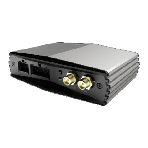
•Designation: MURS Transponder/AIS Receiver
•Physical Serial interface: RS232 or IEC 61162
•Power Supply: 12.6V
•Power Consumption: Less than 10 watts
•Temperature: (per IEC 60945)
-25°C to +70°C (Exposed)
•Compass Safe Distance: 1 meter
Navigation Specifications
•12 channel internal GPS and antenna
Dimensions and Weights
•Diameter: 2.0 in.
•Height: 25.0 in.
•Weight: 3 lbs.
Frequencies and Channel Bandwidth
•RX AIS: 161.975 – 162.025 MHz
at 25 kHz channel spacing
•RX MURS: 151.820 MHz, 151.880 MHz,
151.940 MHz at 11.25 KHz channel spacing
154.570 MHz, 154.600 MHz
at 20 KHz channel spacing
MURS Transmitter
•TX MURS: 151.820 MHz, 151.880 MHz,
151.940 MHz at 11.25 KHz channel spacing
154.570 MHz, 154.600 MHz
at 20 KHz channel spacing
•Power Output: ≤2 watts
•Harmonic Emission: ≤-53 dBc
•Spurious Emission: ≤-53 dBc
•Frequency Accuracy: +/- 3ppm
MURS Receiver
•Data Rate: 9,600 bps
•Error Rate: ≤20% at –107 dBm
•Adjacent Channel Rejection: 60 dB
•Blocking: 70 dB
•Intermodulation: 60 dB
•Large Signal PER: <1%
•Image Rejection: 70 dB for 20% PER
•Spurious Rejection: 70 dB for 20% PER
AIS Receiver
•AIS Data Rate: 9,600 bps
•Sensitivity: ≤20% PER at –107 dBm
•Adjacent Channel Rejection: 60 dB at 25 kHz
•Blocking: 70 dB
•Intermodulation: 60 dB
•Large Signal PER: < 1%
•Image Rejection: ≥70 dB for 20% PER
•Spurious Rejection: ≥70 dB for 20% PER
Short Text Messages (STM)
•Transmission Protocol: CSTDMA
•STM Types:
Private: for communication with a specific unit
Broadcast: for communication with any unit set to
listen to broadcast messages
Group: for communication with units that have
selected the sender as part of their defined group.
For additional information on the construction and transmission
Logical Serial Interface Details:
The logical serial interface of the SM150 is a subset of IEC
specification 61993-2, using a 38.4 kbps connection to a host
computer. The received AIS messages are output using the
VDM sentence, and GPS location data is output using the
NMEA 0183 sentences.
To request full serial interface specifications, please e-mail
Simple Marine Installation
1.Attach the SM150 to a standard
1” x 14 threaded antenna mount.
2.Connect the power cable to a 12
volt power source.
3.Connect the ground lug to a solid
ground.
Optionally connect the serial interface cable to a
PC for STM applications and visual display.
WARRANTY INFORMATION
Shine Micro warrants its products to be free from defects for one full
year from the date of purchase. Shine Micro will, at its sole discretion,
repair or replace any components that fail in normal use. Labor and
material costs for such repairs or replacement will be free of charge.
This warranty does not cover failures due to abuse, misuse, accidents,
or unauthorized alterations or repairs
TRACKER SM150 Low Cost AIS/MURS Transponder
©2006

