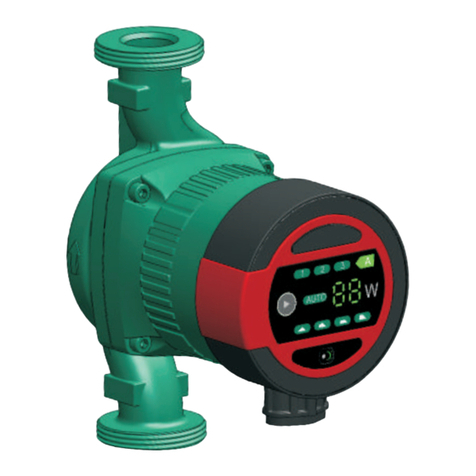
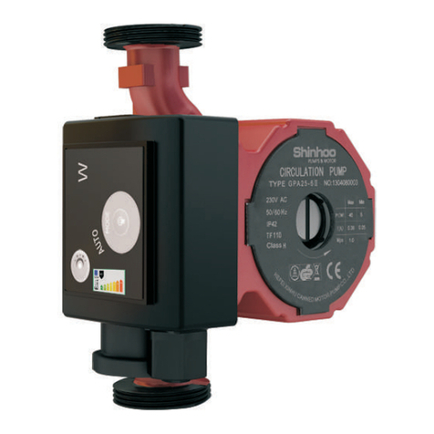
Shinhoo LPA Series User manual

Installation and Operating
Instructions
Microcirculation Series Energy-saving
pipe Canned Motor Pump

Precautions for use of LPA Series products
01.
08.
02.
09.
03.
10.
04. 11.
12.
05.
13.
06.
07.
Read the installation manual installation and maintenance.
carefully before installation and For circulation of domestic hot
use. water, copper or stainless steel
The manufacturer will not be motor pump body shall be used.
liable for any personal injury, Heat supply pipelines shall not
motor pump damage and other be frequently filled with non-
property damage due to failure softened water so as to avoid
t o c o mp l y w it h c o nt en t s increa sing c alcium in the
specified in safety warning circulating water inside the
signs. pipeline, which may thus block
The installers and operators must the impeller.
co m pl y w i th l o cal s afe t y Do not start the motor pump
regulations. without pumping liquid.
The user must confirm that only Some models are not suitablefor
q u a l i f i ed p e r s o n n e l w i t h pumping drinking water.
professional certification and
Motor pump liquid may be high-
proficiency of this manual is
temperature and high-pressure;
allowed to install and maintain
therefore, the liquid in the system
this product.
must be completely drained or
The microcirculation series the shut-off valves on both sides
energy-saving pipe canned must be closed before moving
motor pump(also called in and dismantling the motor pump
a b b r e v i a t i o n o f “ m o t o r to prevent burning.
pump”) must not be installed
Ventilation must be ensured in
in a place that is damp or may be
su m mer o r h i gh a mbie n t
splashed by water.
temperature period to avoid
For convenient access of condensation that may cause
maintenance, a shut-off valve electrical malfunctions.
shall be installed on each side of
inlet and outlet of the motor
pump.
The power supply of the motor
pump shall be cut off before
GPA Series

14.
21.
15.
16.
17.
18.
19.
20.
If in winter, the pump system place under room temperature.
does not work or when the This appliance can be used by
ambient temperature drops children aged from 8 years and
below 0 ℃ , liquid in the piping above and persons with reduced
system shall be completely physical, sensory or mental
drained so as to avoid frost capabilities or lack of experience
cracking of motor pump body. and knowledge if they have been
If the motor pump is left unused given supervision or instruction
for a long time, please close the concerning use of the appliance
pipe valve in the inlet and outlet in a safe way and understand the
of the pump and cut off the hazards involved. Children shall
power supply of pump. not play with the appliance.
Cleaning and user maintenance
If the flexible cord of cable is shall not be made by children
damaged, it must be replaced without supervision.
by a qualified person.
Please close the valve at the inlet
of motor pump and cut off power
of the motor pump immediately if
overheating and abnormality of
motor is detected, and contact
your vendor or service center
immediately.
If trouble cannot be addressed
according to the manual, please
close the valves on the inlet and
outlet of the motor pump
immediately, cut off power
supply of the motor pump and
contact your vendor or service
center immediately.
This product shall be put in a
place out of reach of children.
After installation, take an
isolation measures to avoid
access of children.
This product shall be stored in a
dry, well ventilated and cool
GPA Series

Warning
Warning
1.
Before installation, you must carefully read the installation
and operation manual. The installation and use of the
equipment must comply with local regulation and applicable
operation standards.
Those who have weak physical strength, react slowly and
lack experience and knowledge (including children) can use
this motor pump only under the monitoring and direction of
his/her safety personnel.
Signs
Failure to comply with this safety instruction may lead to
personal injury!
Failure to comply with this safety instruction may lead to
equipment malfunction or damage!
Note or instruction for easy and safe operations.
Caution
Note
01
GPA Series

2. General:
The motor pump is easy to install maintenance-free, low noise, automatic
regulation performance which is the best choice for hot-water circulation
system。
Main application:
1.Heating and Domestic hot-water circulation system
2.Water heater circulation system
02
Liquid temperature
<85℃ 95℃
Inlet pressure
0.05bar 0.28bar
0.5m head
3. Operation Conditions
3.1 Power supply
Voltage 220V-240V, frequency 50/60Hz, single-phase AC power.
3.2 Ambient Temperature
Ambient temperature: 0 ℃~ +40 ℃
3.3 Medium (liquid delivery) temperature
To avoid condensation in terminal box and the stator, the temperature of liquid
pumped by the motor pump must be always higher than ambient temperature.
3.4 System pressure
Maximum pressure 1.0MPa(10bar).
3.5 Degree of Protection
IP44
3.6 Inlet pressure
To avoid damage to the motor pump bearing due to cavitation noise, the motor pump
inlet shall maintain the following minimum pressure:
2.8m head
GPA Series

03
3.7 Pumping liquid
The pumping liquid includes thin, clean, non-corrosive and non-explosive
liquid which shall not contain any solid particles, fiber or mineral oil, and motor
pump must definitely not be used to pump inflammable liquid such as rapeseed oil
and gasoline. If the motor pump is used in a place with relatively high viscosity, the
motor pump has lower performance. So when choosing a motor pump, the
viscosity of liquid must be taken into account.
4.1 Installation
·
·
·
When installing microcirculation series energy-saving pipe canned motor pump, the
arrow on motor pump casing indicates the flow direction of liquid through the pump.
When installing the motor pump in the pipeline, two gaskets must be installed at the inlet
and outlet.
During the installation, the shaft of motor pump must be horizontal.
4. Installation
GPA Series

04
Schematic diagram for Installing Temperature Controlled Plug
Schematic diagram for Installing Battery
GPA Series

05
5. Electrical connection
1 2 3
4 5 6
Electri cal connectio n and
protection shall comply with
local codes and norms.
Th e m oto r p ump
needs no protection
from external motor.
·Check if the supply voltage
and frequency are the same
as parameters indicated on
the nameplate of the motor
pump.
· Connect the motor pump
and power supply with the
plug supplied together with
the pump.
·After the power is supplied,
the indicator lamp on the
control panel is ON.
GPA Series

06
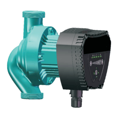
6.Control panel
1
2
3
4
5
6
7
8
9
Position Descriptions
Indicating constant speed running mode
Indicating Auto operation mode
Indicating temperature control mode
1.Power indicated
2. running (or stop) time indicated in timing mode
Running (or stop) hours setting in timing mode for display
Running (or stop) minutes setting in timing mode for display
Power unit shown under normal operation
1.Switch on various running modes
2.Increasing time in timing mode
Decreasing time in timing mode
GPA Series

7.Control of Motor Pump
7.1 The constant speed running mode
Motor pump runs in the constant speed when it is in constant speed running
mode. Green light 1 as well as light 4 which is showing current power, will be
always on while the light 7 will also be on.
7.2 The auto operation mode
Motor pump will automatically exert necessary adjustment according to
current systematic performance when it is in the auto operation mode. Green
light 2 as well as light 4 which is showing current power, will be always on
while the light 7 will also be on.
7.3 Temperature control mode
Temperature sensor will obtain the feedback in terms of fluid temperature
and make a judgment on whether start or stop when it is in the indicating
temperature control mode. In such mode, the motor pump will stop when
temperature is over 50 centigrade, but it will run in constant speed when
temperature is below 36 centigrade. Green light 3, as well as light 4 which is
showing current power, will be on while the light 7 will also be on.
7.4 Timing mode
Motor pump will run in constant speed within time set by time controller when
it is in timing mode. The light 4 indicates the current time by showing the
hour and minute alternately. When it comes to the hour, light 5 will be on
while light 6 is on in the case of showing the minute. User can set and inquire
the start and end time point for 3 periods about the running of pumps. And
time points for 3 period are unnecessary to be reset when the power is off
due to the controller can keep a record of running parameters set by users
automatically.
7.5 Flushing function
When pumps are in the mode of standby for 8 hours, pumps will restart
automatically and then flush the pipe for 15 minutes. At the moment, it runs
in the constant speed mode. The flushing function is effective when it is in
either Temperature control mode or Timing mode. Under the circumstance,
the light 7 is on as well as light 4 is shining and the current running power is
presented.
GPA Series
07

7.6 Key pressing specification
The factory setting for pumps is that it is in the constant speed running mode.
When the power is on, Slightly pressing on “8 can help you switch
between different running modes.( it can be switched among the constant
speed running mode, the auto operation mode, temperature control mode
and timing mode.)
·Illustration for the timing mode setting
The light 4 will show the current time when it is in the timing mode. Hour and
minute are presented alternately.
The first step: Entering the timing mode( only in the timing mode the
setting of the timing mode is available.):
Pressing “8 ”and “9 ”for for 3s then setting mode is activated. In
the mode, light 4 is flashing and 88 positions shows the time period.(F0-F6)
The second step: settings for the current time and timing time:
When it comes to the setting mode,”88” can be switched from F0 to F6:
F0-F6 represents 7 time periods and their significance are presented below
F0 settings on current time
F1 settings on the start time of the first period
F2 settings on the end time of the first period
F3 settings on the start time of the second period
F4 settings on the end time of the second period
F5 settings on the start time of the third period
F6 settings on the end time of the third period
After firstly pressing “9 ” for 3s,Setting on hours is available (light 5 is
flashing) and now the current hour is shown. When pressing“9 ”,one hour
has been cut while pressing “8 ”vice versa.
If it is set then please socondly long press the “9 ”for 3s,Setting on minute
is available ( light 5 is flashing). When pressing “9 ”,one minute has been
cut while pressing “8 ”vice versa.
After thirdly long pressing “9 ”for 3s
Settings on the next time period is available ( For instance if F0 has been set
currently, then next step is for F1) and others are the same.
The third step: Quit the setting mode:
When any state from F0 to F6 is shown on the 88 position,and after long
pressing “8 and “9 ” for 3s, user can quit the setting mode;Now the time
is shown normally ( light 4 shows current time)
Range for time setting is 24 hours and all hour figure can be set from 0 to 23
as well as minute figure set from 0 to 59. Once finishing the setting and quit
the corresponding mode, the hour and minute shows alternately;
For example: when showing 8 in terms of 8:30 AM, the light 5 is on and when it
comes to 30 the light 6 is on.in addition, when showing 13 in terms of 1:25 PM,
the light 5 is on and light 6 is on when it comes to showing the 25. It will take
2s for switching time and showing alternately.
GPA Series
8

If users don't need 3 time period timing function and only one of them is
needed, the other two time periods are not necessary to be set in terms of
factory settings.( both of them can also be set as some same time).
If users only need one time period ,which is from 17:30 to 21:30 ,to be set and
runnning of pumps is not required at other time period, then we can make
some adjustments as following:
Time period Hour Minute
F1 17 30
F2 21 30
F3 0 0
F4 0 0
F5 0 0
F6 0 0
The time for factory setting is defaultly set as 0 and it can be modified as any
other identical values ,but it must make sure the rest of time periods shares
the same.
·Illustration for inquire on the time in timing mode:
In the timing mode:
After firstly long pressing the “8 ”for 3s,
Now the inquiry function for setting time is activated and it shows the current
time(F0). The figures for the hour and minute set by users are both showing
alternately and at the same moment LED light is flashing. Then short press
“8 ”and F1 mode is available. It plays the same rules for others and such
kind of function can help users to check the accuracy of time.
After long press “8 ” for 3s,Then quit the inquiry mode.
7.7 Indication lamp area of power consumption of motor pump
After the power is connected, the light 4 is on and the monitor in Position 4
works.During operation, the indicated value is in Watt, showing the actual
power consumption of the motor pump. When the motor pump fails to work,
the monitor indicates :
Fault Code
E2
E4
E5
E6
light 3
Red LED light is on
Description
Over-current protection
Open-phase protection-phase protection
Locked-rotor protection
Motor start failure protection(Motor
parameters do not match)
If malfunction is detected, the power supply must be cut off before trouble-
shooting. After the trouble is addressed, re-connect the power and start the
motor pump.
GPA Series
09

8.Technical Parameters and Installation
Dimensions
8.1 Technical Parameters
To prevent condensation in the terminal box and rotor, the temperature of
pumping liquid of the motor pump must be always higher than ambient
temperature.
For domestic hot water, it is suggested that water temperature should
remains below 65℃ to reduce scaling.
Power Supply Voltage
Motor Protection
Degree of Protection
Input power
Insulation Class
Relative Humidity(RH)
The system pressure
Suction Port Pressure
EMC Standard
Sound Pressure Class
Ambient Temperature
Temperature Grade
Surface Temperature
Liquid Temperature
220-240V, 50/60Hz
the pump needs no external protection
I 44
P
GPA15-1.5B 8W
GPA15-1.5LB 5W
F
Max. 95%
1.0 MPa
Liquid Temperature
≤+85℃
≤+95℃
Minimum Inlet Pressure
0.005 MPa
0.028MPa
EN61000-3-2 and EN61000-3-3
EN55014-1 and EN55014-2
The sound pressure level of the motor pump
is lower than 42dB(A)
0~+40℃
T 95
F
The maximum surface temperature is not higher
than +110℃
2~+95℃
GPA Series
10

8.2 Installation Dimensions
Power
(W)
8
5
Model
GPA15-1.5B
GPA15-1.5LB
Material
of Pump
Body
Control Mode of Motor Pump
Constant
speed running
mode
Auto
operation
mode
Temperature
control
mode
Timing
mode
Flushing
function
GPA Series
11

8.3 Nameplate Instructions
NO.
1
2
3
4
5
6
7
8
9
10
11
Descriptions
Product Model
Frequency (Hz)
Max Current (A)
Degree of protection
Maximum system load bearing (Mpa)
unrecyclable label
Authentication mark
Temperature class
Insulation class
Power(W)Maximum mode maximum input power P1
Voltage (v)
GPA Series
12

8.4 Model Instructions
The model of motor pump is composed of capitalized Latin letters and Arabic
numbers, which means:
L: functions of simplified versions and it is
omitted for the full fuctions.
B: steel material of pump body and it is
omitted for the cast iron pump body
maximum head of delivery of pump (m)
rated diameters of inlet and outlet of pump (DN)
Pipeline Canned Class-A Energy-saving Motor Pump
Model Example: GPA15-1.5B means the inlet and outlet diameter of pump in which
pump body made of bronze are DN15 with 1.5 meters of maximum head.
9. Performance Curve
Every setting of the motor pump has corresponding performance curve (Q/H
curve).The input power curve (P1 curve) belongs to every Q/H curve. Power
curve represents the power consumption of motor pump in given Q/H curve
with Watt as the unit. P1 value corresponds to the readings taken from the
monitor of motor pump.
9.1 Guide on Performance Curve
9.2 Curve conditions
The followings are applicable to the performance curve specified in the
Microcirculation series manual:
· Test liquid: air-free water.
· Applicable density of curve ρ=983.2 kg/m3, and liquid temperature
+60℃.
· All curves represent averaged value, and shall not be used as guarantee
curve. If a specific performance is needed, then separate measuring shall
be conducted.
GPA Series
13

9.3 Performance Curve
GPA Series
14

10.Trouble-Shooting Schedule
Corrective Action
Fault
Control Panel
Indication
lamp “Off”
Cause
Indicating“E2”
Motor pump
cannot
be started
The circuit breaker of
current control or voltage control
opens
Connect the circuit
breaker
Warning
Before conducting any maintenance and repair of the motor pump, ensure that
power supply has been cut off and will not be connected accidentally.
Failure of motor pump Replace the motor pump
Under voltage inspect whether power
supply is in specified range
Over-current protection Replace the motor pump
Indicating“E4”
Open-phase protection Replace the motor pump
Indicating“E5”
Locked-rotor protection Replace the motor pump
Indicating“E6”
Motor start failure
protection(Motor
parameters do not match)
Replace the motor pump
Meaning of crossed –out wheeled dustbin:
Do not dispose of electrical appliances as unsorted municipal waste, use
separate collection facilities. Contact your local government for information
regarding the collection systems available. If electrical appliances are
disposed of in landfills or dumps, hazardous substances can leak into the
groundwater and get into the food chain, damaging your health and well-
being. When replacing old appliances with new ones, the retailer is legally
obligated to take back your old appliance for disposals at least free of
charge.
GPA Series
15

Product warranty book of Hefei Xinhu
Hefei Xinhu Canned Motor pump Co., Ltd provides 12 months’ quality assurance for
the products since the sales date, and shall be responsible for the product failure or
damage caused by manufacturing and material defects. The warranty is on condition that
the installation of product should be in line with Xinhu Installation and Use Manual and
recognized good operation specification.
This warranty does not apply to the product ailure or damage caused by ① use
the product other than for the usage recommended by Xinhu; ② misuse of the product
that does not conform to Xinhu Installation and Use Manual; ③ improper maintenance and
handling of product; ④ disassemble products and replace parts by oneself.
Any product provided rather than manufactured by Hefei Xinhu Canned Motor pump
Co., Ltd should comply with the quality assurance provisions of the manufacturer.
Within warranty period, the product repair is guaranteed by purchase invoice and
warranty bill. Please send or return the product in need of repair to the local dealer of Hefei
Xinhu Canned Motor pump Co., Ltd. or designated maintenance point for repair. Hefei
Xinhu Canned Motor pump Co. may determine whether home maintenance service shall
be provided for free in accordance with its maintenance policies in the local. Guarantee
repair of parts is free.
Hefei Xinhu Canned Motor pump Co., Ltd. will not accept claims to damage which
should be borne by a third party or caused by product failure of any other company.
Hefei Xinhu Canned Motor pump Co., Ltd shall not be responsible for the product
failure or damage due to abnormal operating conditions, war, riot, wind (rain) storm,
disaster or other force majeure.
Hefei Xinhu Canned Motor pump Co., Ltd reserves the power of interpretation on the
unaccomplished matter in the product warranty book.
HEFEI XINHU CANNED MOTOR PUMP CO., LTD
Hi-Tech Industrial Development Zone, Hefei, P.R. China.
GPA Series
16
Other manuals for LPA Series
1
Table of contents
Other Shinhoo Water Pump manuals
Popular Water Pump manuals by other brands

Jefferson
Jefferson JEFSUBPDW266-95 user manual

SKC
SKC AirChek 3000 operating instructions

SFA-SANIFLO
SFA-SANIFLO SANICUBIC 1 instruction manual

KNF
KNF FEM 1.02 Operating and installation instructions

MBH
MBH SP-7 Instruction, Installation, Operation and Maintenance Manual

VEHNS GROUP
VEHNS GROUP XZ YEAZ user manual

Intex
Intex Quick-Fill 58609 Operation instructions

Sumak
Sumak SMH120 INTRODUCTION AND USER'S GUIDE

Impact Pumps
Impact Pumps SolarPlex SPX-800-5 Quick start user guide

Australian Pump Industries
Australian Pump Industries AUSSIE SEAMASTER owner's manual

Pratissoli
Pratissoli HF-WK Series instruction manual

EHEIM
EHEIM 1260 manual