Shinkawa VM-5 User manual

MANUAL NO. 20002E2.0
Published in Dec.2000
Revised in Nov. 2012
VM-5 SERIES MONITOR
MODEL VM-5P3 Phase Marker Unit
INSTRUCTION MANUAL

SAFETY CONVENTIONS VM-5P3
i
For safe operation.....
Thank you for using our VM-5 Series Monitor. SHINKAWA Sensor Technology applies strict quality control
and inspections to ensure the high reliability of its products.
This instruction manual contains descriptive information, specifications, and operating, setting, and adjusting
procedures.
Please study the contents of this manual and related manuals thoroughly before installing or operating the
equipment, and keep it handy for future reference.
"Safety Conventions"
Please thoroughly study the following section entitled "Safety Conventions" before operating the
equipment.
The safety symbols explained in this section are placed outside the left margin next to the text to which they
apply.
This unit is designed for use by specialists or persons thoroughly familiar with the field.
Make sure that the end user receives the Instruction Manual delivered with this unit.
Before use.....
When the unit is received, inspect it for damage suffered in transport and check
whether it is the item you ordered. In the unlikely event that it was damaged in transport
or does not function according to specifications, please contact the SHINKAWA Office
or the dealer nearest to you.
Store the unit under the ambient conditions given in the specification.
Avoid places where it is exposed to high humidity or corrosive gases.
Storage…..
In case the product needs to be stored temporarily for certain reasons after its acceptance at the site, store it in
a warehouse with less humidity. Note that if stored in any of the following environments, its appearance and
functions may deteriorate, and also its service life may shorten.
(1) There is much dust.
(2) There are corrosive gases (such as SO2, H2S, etc.).
(3) The product is exposed to vibration and/or shock.
(4) The product is exposed to the direct sunshine and/or high temperature.
(5) The product is exposed to water, steam and/or high humidity.

SAFETY CONVENTIONS VM-5P3
ii
Make it a rule to follow the instructions given in this manual.
This manual contains important information designed to prevent personal injury and property damage, and
ensure safe operation of the equipment.
Familiarize yourself with the signs and symbols explained below before proceeding to read the manual, and
observe the instructions given.
■Explanation of signs
Symbols Explanation
WARNING Indicates a potentially hazardous situation which, if not avoided, could result in death
or serious injury.
CAUTION Indicates a potentially hazardous situation which, if not avoided, may result in minor
or moderate injury. It may also be used to permit for property-damage-only accidents.
◊"Serious injury" refers to such injuries as loss of eyesight, injuries, burns (due to heat or cold), electric
shock, fractures, and poisoning, that have permanent after effects and require hospitalization or long-term
outpatient treatment.
◊"Moderate or minor injury" refers to such injuries as burns and electric shock that do not require
hospitalization or long-term outpatient treatment. "Property-damage-only accidents" refers to
consequential damage related to destruction of property and damage to the equipment.
■Explanation of symbols
Symbols Explanation
Indicates a prohibited action.
Details are given in the text next to the symbol.
Indicates a mandatory action.
Details are given in the text next to the symbol.

SAFETY CONVENTIONS VM-5P3
iii
To ensure safe use of this equipment, strictly observe the safety precautions provided in this manual, as well
as installation methods and methods of use stipulated by laws and regulations. SHINKAWA Sensor
Technology will not be liable for damage, etc. due to methods of use contravening to the instructions provided
here.
■Safe use
WARNING
Make sure to ground.
May cause electric shock or malfunction.
Make sure to turn the power off before any wiring work.
Will cause electric shock.
CAUTION
Connect the input signal within the voltage range described in the
specification to the input terminals.
Will cause damage and malfunction of the instrument.
Install the monitor unit in the desired location in the instrument rack.
Will cause damage to the instrument and malfunction of the turbine monitoring system.
A printed circuit board and electronic products may receive damage with
the static electricity of a human body.
Touch the metal part once and discharge your static electricity before
dealing with it.
Will cause damage and malfunction of the instrument.
Do not touch parts and soldered surfaces of the monitor unit.
Will cause damage and malfunction of the instrument.
The monitor unit is a precision instrument.
Take care not to expose it to excessive shock or vibration.
Do not change the parameter settings during operation.
May cause unexpected alarm output.
Do not pull out the face plate during operation.
Will cause damage to the instrument and malfunction of the turbine monitoring system.
Do not measure insulation resistance and dielectric strength other than
those at places specified.
Will cause damage to the instrument.
Do not remodel this monitor unit without permission.
Otherwise the guarantee can not be made.
PROHIBITION
MANDATORY
MANDATORY
PROHIBITION
PROHIBITION
PROHIBITION
PROHIBITION
PROHIBITION
PROHIBITION
Connect earth wire
MANDATORY

SAFETY CONVENTIONS VM-5P3
iv
■EMC(Electro-magnetic compatibility)
The EMC of each VM-5 Series monitor is evaluated by various noise tests.
However, its characteristics may vary with on environmental conditions such as the magnitude of noise,
ambient temperature, humidity and the arrangement of equipment.
For the above reason, when operating the monitor, please observe the following CAUTION.
CAUTION
The unit should be operated by specialists or personnel who have
knowledge of it.
When a shielded cable is used, the length of the unshielded cable section
should be less than 100mm. (3.937in REF.).
For each relay used near this unit, devices related to this unit or signal
cables connecting the unit and these devices, install a surge killer.
Firmly tighten each screw used for mounting each unit. In additional,
always close the face plate for the unit, then fix it with knurled screws.
In order to prevent the system from its malfunction when the unit fails,
provide the systematic interlock function.
Do not wire input signal cables in parallel with control and power cables.
It is recommended that separated wire ducts be used for these cables.
Do not use any radio equipment near the unit.
■Noise filter
Noise transmitted through each cable may be rejected to some extent by inserting a ferrite core in the cable
(note 1).
If the cable passes through noisy surroundings, it is recommended that such a noise prevention device is used.
(note 1) ZCAT3035-1330 : TDK
MANDATORY
MANDATORY
MANDATORY
MANDATORY
MANDATORY
PROHIBITION
PROHIBITION

TABLE OF CONTENTS VM-5P3
v
1. GENERAL INFORMATION
1-1 OVERVIEW ----------------------------------------------------------------------------------- 1
2. SPECIFICATIONS
2-1 SPECIFICATIONS -------------------------------------------------------------------------- 2
3. OUTLINE DRAWING
3-1 OUTLINE DRAWING ----------------------------------------------------------------------- 3
4. INTERCONNECTION
4-1 INTRINSIC SAFETY EXPLOSION-PROOF CONSTRUCTION ---------------- 5
4-2 NON-INTRINSIC SAFETY EXPLOSION-PROOF CONSTRUCTION --------- 7
4-3 OK ALARM CONTACT OUTPUT WIRING ------------------------------------------- 9
4-4 INTERCONNECTION OF BUFFER OUTPUT --------------------------------------- 10
5. DESCRIPTION OF FUNCTIONS
5-1 DISPLAY -------------------------------------------------------------------------------------- 11
5-2 OK (INPUT ABNORMAL) ALARM ------------------------------------------------------ 11
5-3 OK ALARM RELAY MODE --------------------------------------------------------------- 12
5-4 OK ALARM RESET MODE --------------------------------------------------------------- 13
5-5 MONITOR OUTPUT ------------------------------------------------------------------------ 13
5-6 PULSE OUTPUT ---------------------------------------------------------------------------- 13
5-7 TRIGGER FUNCTION --------------------------------------------------------------------- 13
5-8 SELF-DIAGNOSTIC FUNCTION ------------------------------------------------------- 13
6. DESCRIPTION OF PARTS
6-1 NAME OF PARTS --------------------------------------------------------------------------- 14
6-2 DESCRIPTION OF PARTS------------------------------------------------------------------ 15

TABLE OF CONTENTS VM-5P3
vi
7. BLOCK DIAGRAM
7-1 BLOCK DIAGRAM -------------------------------------------------------------------------- 17
7-2 FUNCTIONAL BLOCK DESCRIPTION ----------------------------------------------- 18
8. OPERATING METHOD
8-1 WITHDRAWAL OF UNIT ------------------------------------------------------------------ 19
8-2 CHECKING THE SETTING -------------------------------------------------------------- 19
8-3 SETTING THE PHASE MARKER ------------------------------------------------------ 23
8-4 ALARM RESET MODE SETTING ------------------------------------------------------ 32
8-5 ALARM RELAY MODE SETTING ------------------------------------------------------ 34
8-6 SETTING ABNORMAL INPUT ALARM FUNCTION ON/OFF ------------------- 35
9. MAINTENANCE
9-1 RECOMMENDED MAINTENANCE EQUIPMENT ------------------------------------ 36
9-2 CHECKING THE OPERATION OF
MONITOR OUTPUT OR PULSE OUTPUT -------------- 37
9-3 CHECKING THE OPERATION OF THE INPUT ABNORMAL ALARM ------- 39
9-4 REPLACEMENT OF ALUMINUM ELECTROLYTIC CAPACITOR---------------- 41
10. TROUBLESHOOTING
--------------------------------------------------------------------------------------------------- 42

1. GENERAL INFORMATION VM-5P3
-1-
1-1 OVERVIEW
The VM-5P3 Phase Marker Unit combined with the VM-5H3 or VM-5W1 Instrument Rack
conducts waveform shaping of the phase marker signal and also monitors the OK alarm contact
output and abnormal internal power supply voltage for each rack. In addition, the abnormal phase
marker signal input can be detected by its setting to be able to be output as the OK signal.
• Also carefully read the instruction manuals for the VM-5H3, VM-5W1 Instrument
Racks, and for the respective transducer used.
• Test of cables using megger (insulation test):
Before conducting an insulation test of cables using a megger, always disconnect
these cables from the instrument. Also when connecting them to the instrument
after the test, always short these cables once to discharge charged electrons, then
connect them to the instrument. The instrument may be damaged if connected with
the cables charged with electrons.
• This unit is not intended for use as a single unit and, therefore, does not match the
VM-5G Single Unit Instrument Rack.
• This unit is not provided with the communication function.
Mandatory
Caution
Caution
Caution

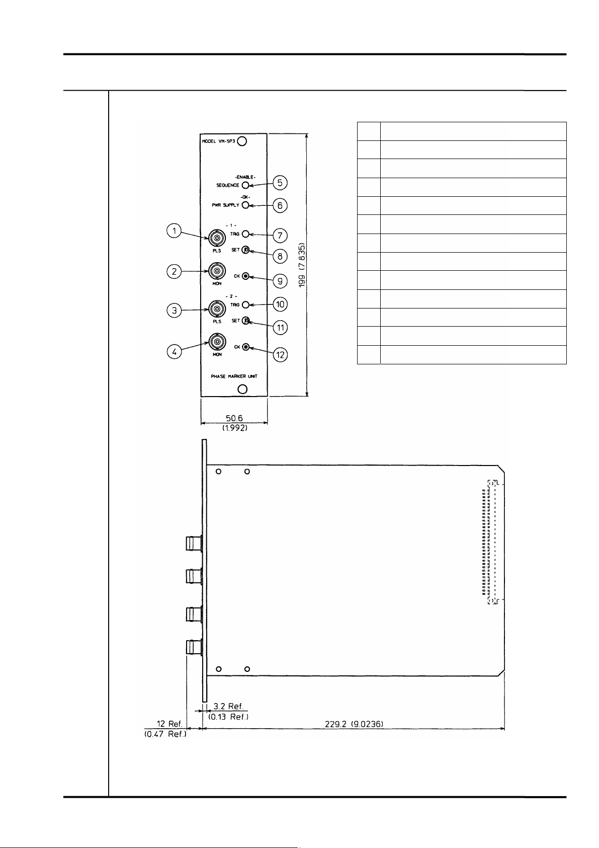
2. SPECIFICATIONS VM-5P3
-2-
2-1 SPECIFICATIONS
Serial interface Input signal
Hysteresis set value
(shaped waveform circuit)
(CH1)
Hysteresis set value
(shaped waveform circuit)
(CH2)
Alarm reset
system OK
Relay mode
system OK Trigger mode Tropical
spec.
CE
marking
3 Not provided 1 VK,RD,FK Series 0 1.0V 0 1.0V 0 AUTO-RESET 0 Auto
1 0.1V 1 0.1V 1 SELF-HOLD 0 NORMALLY
DE-ENERGIZED 1 Manual
2 0.2V 2 0.2V
3 0.5V 3 0.5V 1 NORMALLY
ENERGIZED
ABNORMAL INPUT
ALARM FUNCTION
SETUP
ON(enabled) or OFF(disabled)
Preset to OFF(disabled)
(Can be changed using the internal jumper)
TRANSDUCER
POWER SUPPLY
-24VDC±1V, 20mA
POWER SUPPLY OK
INDICATOR
PWR SUPPLY OK : (green LED)
SEQUENCE STATE
INDICATOR
SEQUENCE ENABLE : (yellow LED)
TRIGGER INDICATOR TRIGGER : (yellow LED)
TEMPERATURE
RANGE
Operating temperature : 0 to 65°C (32 to 149°F REF.)
Storage temperature : -30 to +85°C (-22 to +185°F REF.)
Relative humidity : 20 to 95%RH (noncondensing)
FINISH Face plate : Munsell N-4.0 (equiv.)
DIMENSION OF TARGET(Model VK,RD,FK)
CAUTION) To detect a projection(gear),provide surface A of the projection with a concentric
curve. Do not make it flat.
A= mm
B= mm
C= mm
D= mm
MASS Unit : max.0.6kg (max.1.4lb REF.)
Standard Specifications
POWER SUPPLY Supplied from instrument rack (VM-5H3 or VM-5W1)
PHASE MARKER
SIGNAL
Phase marker : 2ch Max.
Input impedance : Approx.10kΩ
INPUT VOLTAGE 0 to 25VDC
BUFFER OUTPUT Phase marker signal : 2ch
Output voltage : -1 to –20VDC
Output impedance : 50Ω
PULSE OUTPUT Shaped pulse signal is output via a buffer amplifier.
Signal level : -1 to +1V(P
L
), 4 to 6V(P
H
)
Output impedance : 50Ω
OTHER
Note) Model VM-5P3 Phase marker unit can be installed on 1 unit(VM-5P3)/1 rack(VM-5H3 or VM-5W1 Instrument
Rack), can not be installed on Model VM-5G Single Unit Instrument Rack.
The system OK alarm contacts on the instrument rack are not functional unless the VM-5P3 is mounted.
Alarm contact operation
Monitor power ON
Monitor alarm relay mode Monitor power OFF Normal state Alarm state
NO contact NORMALLY DE-ENERGIZED OPEN OPEN CLOSE
NO contact NORMALLY ENERGIZED OPEN CLOSE OPEN
NC contact NORMALLY DE-ENERGIZED CLOSE CLOSE OPEN
NC contact NORMALLY ENERGIZED CLOSE OPEN CLOSE
VM-5P -
Ordering Information Standard Specifications
-
1
- - /TRP/CEM
Model Code / Additional Spec. Code( )
No entry if additional
spec. code is not specified.
3
30007E1.5
Input
VK-202A
RD-05A
FK-202F
VK-452A
FK-452F VK-302P
A ≥6 ≥16 ≥8
B ≥7 ≥20 ≥8
C ≥2.5 ≥4.5 ≥2.5
Dimension of target
[recommended]
(mm) D ≥16 ≥36 ≥20
Set gap
[recommended](mm) 1.0 to 1.5 2.5 to 3.5 1.0 to 1.5
D D
A
CBC

3. OUTLINE DRAWING VM-5P3
-3-
3-1 OUTLINE DRAWING
No. Name
1PULSE OUTPUT (1CH)
2MONITOR OUTPUT (1CH)
3PULSE OUTPUT (2CH)
4MONITOR OUTPUT (2CH)
5SEQUENCE enable indicator
6Power for indicator
7TRIGGER indicator (1CH)
8TRIGGER adjuster (1CH)
9TRIGGER set value check terminal (1CH)
10 TRIGGER indicator (2CH)
11 TRIGGER adjuster (2CH)
12 TRIGGER set value check terminal (2CH)
Finish: Face plate Munsell N-4.0 (equiv.)
Mass: Max.0.6kg (Max. 1.4lb REF.)
Unless otherwise specified, units are in millimeters (mm) and grams (g).
Reference dimensions in parentheses are in inches (in) and pounds (lb).

4. INTERCONNECTION VM-5P3
-4-
• Do not use the blank terminals.
• For interconnection between the transducer and monitor, make sure to use 3-core
shielded cables or pair shielded standard 3-wire instrument cables, since the signal
transmitted is weak.
(Do not use unshielded cables or non-pair shielded multicore cables as the
measured values could be affected by external noise.)
Recommended cables
Cable Recommended Note
CVVS
(3-core shielded cable)
Excellent
Recommended cabling as
per API st’d 670
Normal:
Silver-plated braid
Recommended:
Copper tape shielded
(Core wire: Soft copper wire)
Use conduit pipe (cable rack) for
wiring.
INSTRUMENT CABLE
(Pair shielded standard 3-wire)
Good
Although vibration and displacement
signals can be transmitted in one
instrument cable, use separate
cables, because a high vibration
signal exerts injurious influence over
other displacement and vibration
signals.
Recommended:
Outside shield of aluminum or
copper tape.
• Provide separate cabling for pulse signals (phase marker, revolution) and for
displacement and vibration signals.
• Avoid running signal transmission cables together with control and power cables.
• Install all cables in conduit pipes or on cable racks.
Prohibition
Mandatory
Conduit Pi
p
e
Shielded wire
Conduit Pipe
Shielded wire
Outside shielded
Mandatory

4. INTERCONNECTION VM-5P3
-5-
4-1 INTRINSIC SAFETY EXPLOSION-PROOF CONSTRUCTION
Safety Barrier Terminals Monitor Terminals
Hazardous area Safe area 1ch 2ch
Signal name Wire no.
No. No. Terminal name No. Terminal name No.
Output A 4 2 IN A1 IN B1
Common, Shield B, D Earth Earth COM A2 COM B2
Power C 3 1 PWR A3 PWR B3

4. INTERCONNECTION VM-5P3
-6-
•Be sure to observe the following cautions at the time of interconnection.
Note No.
in drawing Caution
1)
Use flexible armored cables as sensor cables and extension cables, unless these
cables are not at risk for damage.
Allowable bending radius
Without armor : 30 mm (1.18 in REF.)
With armor : 50 mm (1.97 in REF.)
Allowable tension : 98.1N (10 kgf REF.)
2)
To insulate the connector, cover it with the supplied shrink tube (insulating
sleeve) or insulating tape.
Take measures to prevent oil or water from entering the insulating sleeve or
tape.
3)
Make sure to fix the terminal cover on the terminal block of the VK driver.
Install the driver in the driver housing and fix the cable securely with a clamp
near the terminal block.
Isolate the driver with an insulator.
4) Shorten the unshielded section (connected section) as much as possible.
(Recommended length : Less than 100mm(3.937 in REF.))
Connect the shielded wires to the COM terminal.
5)
Use a 3-core shielded cable with AWG No. 14 to No. 18 gage stranded
conductors for wiring between the VK driver and the safety barrier, and
between the safety barrier and the monitor. In addition, as the length of each
cable is subject to restrictions, select it as instructed in the dedicated wiring
diagram or the instruction manual for the driver.
Do not put the cable in the same duct accommodated with high-voltage
distribution cables, or do not mix it with power or control cables.
6) Install the safety barrier in the enclosure.
7) For the safety barrier, conduct the following grounding.
• Ground resistance : Less than 10Ω
• Grounding wire : To be grounded separately from other wiring
•Make sure to turn the power off before wiring work to prevent accidents due to
electric shock.
• Do not conduct wiring while the machine is under operation.
• Pay attention to sensor sensitivity.
If connection is conducted as instructed in this connection diagram, the monitor input
(voltage) may drop about 1% by the resistance of safety barrier.
Mandantor
y
Warning

4. INTERCONNECTION VM-5P3
-7-
4-2 NON-INTRINSIC SAFETY EXPLOSION-PROOF CONSTRUCTION
Connected terminals
1CH 2CH
Signal name Wire No.
Terminal name Terminal No. Terminal name Terminal No.
Output A IN A-IN IN B-IN
Common, Shield B, D COM A-COM COM B-COM
Power C PWR A-PWR PWR B-PWR

4. INTERCONNECTION VM-5P3
-8-
•Be sure to observe the following cautions at the time of interconnection.
Note No.
in drawing Caution
1)
Use flexible armored cables as sensor cables and extension cables, unless these
cables are not at risk for damage.
Allowable bending radius
Without armor : 30 mm (1.18 in REF.)
With armor : 50 mm (1.97 in REF.)
Allowable tension : 98.1N (10 kgf REF.)
2)
To insulate the connector, cover it with the supplied shrink tube (insulating
sleeve) or insulating tape.
Take measures to prevent oil or water from entering the insulating sleeve or
tape.
3) Isolate the driver with an insulator.
4) Shorten the unshielded section (connected section) as much as possible.
(Recommended length : Less than 100mm(3.937 in REF.))
Connect the shielded wires to the COM terminal.
5)
Use a 3-core shielded cable with AWG No. 14 to No. 18 gage stranded
conductors for wiring between the VK driver and the monitor.
Do not put the cable in the same duct accommodated with high-voltage
distribution cables, or do not mix it with power or control cables.
•Make sure to turn the power off before wiring work to prevent accidents due to
electric shock.
• Do not conduct wiring while the machine is under operation.
Mandantory
Warning

4. INTERCONNECTION VM-5P3
-9-
4-3 OK ALARM CONTACT OUTPUT WIRING
•Beware of electric shock from high-voltage parts.
•Do not exceed the allowable contact capacity of the alarm contacts.
• The OK alarm contacts are not functional unless the VM-5P3 is mounted.
Caution
Caution
VM-5P3 In
p
ut/out
p
ut terminal block
BUF
SEQ
COM
COM
N.C
OK
N.O
FLT
COM
RES
NC contact out
p
ut
NO contact out
p
ut
A
larm contact out
p
ut
Warning

4. INTERCONNECTION VM-5P3
-10-
4-4 INTERCONNECTION OF BUFFER OUTPUT
• Make sure to insulate the buffer output against earth.
If not insulated, a 2-point earth system results, which may cause noise interference.
CH1
Buffer output
VM-5P3 Input/output terminal block
BUF
COM
IN
COM
PWR
SERIAL INTERFACE
IN
COM
PWR
BUF
COM
B
A
DISABL
ENBL
DAN.BYPS
IN
OUT
CH2
Buffer output
N.C

5. DESCRIPTION OF FUNCTION VM-5P3
-11-
5-1 DISPLAY
5-1-1 POWER SUPPLY OK INDICATOR (GREEN)
Usually, is being lit. Flashes when the internal power supply voltage supplied from the power
unit becomes abnormal, but goes off at a power supply voltage of +5V. Also goes off if the
power is not supplied to the instrument rack (power supply unit).
5-1-2 SEQUENCE INDICATOR (YELLOW)
Lit when the sequence (option filter on occasion) is enabled.
5-1-3 TRIGGER INDICATOR (YELLOW)
Lit while the phase marker signal is being waveform-shaped. May flash or flicker depending on
the frequency of the input signal, but this is not abnormal. Therefore use the unit as usual.
5-2 OK (INPUT ABNORMAL) ALARM
5-2-1 DESCRIPTION OF FUNCTION
The VM-5P3 Phase Marker Unit, when it detects the OK alarm raised by each monitor unit housed
in the same instrument rack, the abnormal internal power supply voltage supplied from the power
supply unit or the abnormal input voltage of the phase marker signal (monitoring of the input
voltage of the phase marker signal can be made enabled by the setting) is detected, can perform
their OR logic operation to output a typical contact signal. In addition, if the internal power
supply voltage supplied from the power supply unit becomes faulty, the contact signal is output
and also the power supply OK indicator on the face plate is made flashing or going off.
• It is recommended that the alarm contact output be normally energized
(de-energized alarm).
The relay may not be able to be energized when the internal power supply becomes
abnormal.
Warning

5. DESCRIPTION OF FUNCTION VM-5P3
-12-
5-2-2 OK ALARM OUTPUT ITEM MATRIX
Divided Details
Monitor unit abnormal When the OK alarm is being raised even if the number of
monitor units housed in the same instrument rack is one.
Internal power supply voltage
supplied from power supply
unit is abnormal.
+5V Voltage decrease in power supply
(alarm is raised at less than +4.6V)
+17V Voltage decrease in power supply
(alarm is raised at less than +12V)
+24V Voltage decrease in power supply
(alarm is raised at less than +19V)
-17V Voltage increase in power supply
(alarm is raised at less than -12V)
-30V Voltage increase in power supply
(alarm is raised at less than -19V)
VK Transducer abnormal (Input voltage : more than -1.4V)
• Sensor is shorted.
• Extension cable is shorted.
• Sensor set gap is too small.
• Signal cable is shorted or disconnected between transducer
and monitor.
Phase marker signal abnormal FK Driver, RD Transducer abnormal (Input voltage : more than -1.4V)
• Sensor is shorted or disconnected.
• Extension cable is shorted or disconnected.
• Sensor set gap is too small.
• Signal cable is shorted or disconnected between transducer
and monitor.
• It is recommended that an FK driver, RD tacho-driver be used as a phase marker
transducer.
5-3 OK ALARM RELAY MODE
Each OK alarm contact can be set to either normally de-energized or normally energized.
For details refer to 8. OPERATING METHOD.
OK Alarm contact operation
Monitor power ON
Monitor power
OFF Normal state Alarm state
NO contact NORMALLY DE-ENERGIZED OPEN OPEN CLOSE
NO contact NORMALLY ENERGIZED OPEN CLOSE OPEN
NC contact NORMALLY DE-ENERGIZED CLOSE CLOSE OPEN
NC contact NORMALLY ENERGIZED CLOSE OPEN CLOSE

5. DESCRIPTION OF FUNCTION VM-5P3
-13-
5-4 OK ALARM RESET MODE
The automatic reset function that automatically releases the alarm condition if the input signal and
internal power supply voltage has returned to normal, or self-holding function that holds the alarm
condition until reset by shorting between the RES and COM terminals, can be set.
For details refer to 8. OPERATION METHOD.
• The alarm cannot be reset when the input reaches the alarm level.
5-5 MONITOR OUTPUT
For signal analysis, the input signal is output via a buffer amplifier to the BNC connector at the
front.
• The monitor output signal is not isolated from the input signal.
5-6 PULSE OUTPUT
The input signal is waveform-shaped via the buffer amplifier for trigger state checking and
revolution signal to be output to the BNC connector at the front.
• The pulse output signal is not isolated from the input signal.
5-7 TRIGGER VOLTAGE OUTPUT
Threshold signal (trigger voltage) is output when the phase marker signal is waveform-shaped.
This signal is suitable for such a pin which is sharp at the point such as a circuit tester probe.
(Applicable insertion pin: 2.0ø)
• The trigger voltage output signal is not isolated from the input signal.
5-8 SELF-DIAGNOSTIC FUNCTION
This is the function of detecting failure occurring in the input line such as sensor disconnection or
the imperfect contact of the connector. If any failure is detected, the OK alarm contact is output
and also the OK lamp flashes.
This function is made enabled by setting the internal jumper.
For details refer to 8. OPERATION METHOD.
Caution
Other manuals for VM-5
2
This manual suits for next models
1
Table of contents