C-100
3
SECTION 1
SERVICING NOTES
UNLEADED SOLDER
Boards requiring use of unleaded solder are printed with the lead-
free mark (LF) indicating the solder contains no lead.
(Caution: Some printed circuit boards may not come printed with
the lead free mark due to their particular size)
: LEAD FREE MARK
Unleaded solder has the following characteristics.
• Unleaded solder melts at a temperature about 40 °C higher
than ordinary solder.
Ordinary soldering irons can be used but the iron tip has to be
applied to the solder joint for a slightly longer time.
Soldering irons using a temperature regulator should be set to
about 350 °C.
Caution: The printed pattern (copper foil) may peel away if
the heated tip is applied for too long, so be careful!
• Strong viscosity
Unleaded solder is more viscous (sticky, less prone to flow)
than ordinary solder so use caution not to let solder bridges
occur such as on IC pins, etc.
• Usable with ordinary solder
It is best to use only unleaded solder but unleaded solder may
also be added to ordinary solder.
DESTINATION ABBREVIATIONS
The following abbreviations for model destinations are used in this
service manual.
• Abbreviations
AEP : European area, East European area, CIS area (Moldova)
and Middle East area (Israel) models
AUS : Australian and New Zealand models
CH : Chinese model
CND : Canadian model
ABOUT THE REPAIRING OF BOARD
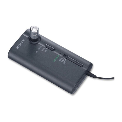
Three boards (SIDE-001 board, SIDE-002 board, SIDE-004 board)
are installed in this unit.
The slide switch (Ref. No. SW1, SW2, SW3) mounted on the SIDE-
004 board can be replaced singly. For the slide switch, refer to
“SECTION 5 ELECTRICAL PARTS LIST” on page 21.
If mounted parts other than the slide switch on the SIDE-004 board
are defective, or if the SIDE-001 board or SIDE-002 board are
defective, replace the all boards.
Schematic diagram and printed wiring board are described for ref-
erence purposes in this service manual.
ABOUT THE REPLACING OF BOARD
The SIDE-001 board, SIDE-002 board and SIDE-004 board are
repair parts as a unit of three boards together, whose voltage ad-
justed at the factory.
Therefore, if it is necessary to replace one of the boards of SIDE-
001 board, SIDE-002 board or SIDE-004 board, be sure to replace
three boards at the same time.
JIG FOR DISASSEMBLING/ASSEMBLING
If it is difficult to attaching or removing the bottom sleeve, please
use a screw cap opener (available on the market) etc.
Note: A screw cap opener of available on the market has various shapes.
Select and use one that fits the shape of the bottom sleeve that will
not scratch this unit.
(The figure below is for reference.)
IMPORTANT NOTE OF AFTER THE REPAIRING COM-
PLETION
After the repair of this unit is completed, be sure to check the op-
eration performance before returning the product to the customer.
Confirm with each service headquarters for checking method.
The SERVICING NOTES contains important information for servicing. Be sure to read this section before repairing the unit.
