manuals.online logo
Brands
  1. Home
  2. •
  3. Brands
  4. •
  5. Shire
  6. •
  7. Outdoor Storage
  8. •
  9. Shire 7x7 Cornershed User manual

Shire 7x7 Cornershed User manual

Assembly of 7x7 Cornershed©
Thank you and congratulations on the purchase of your Shire Garden Building. We believe
that this product will give you many years of excellent service. This is a natural product
manufactured to a high standard therefore if you have any queries or experience any
difficulties then please contact our customer service hotline on 01945 465295.
Preparation of Base
We recommend that the base onto which your building will stand should be at least
75mm larger in each direction than the total floor size of the building.
Actual floor area of the building: 2248 x 2248mm
Total height clearance: 2150mm
The chosen position in your garden for the siting of the building should be excavated to
a depth of 75mm to allow a base of sand, on to which paving slabs can be evenly laid -
THEY MUST BE LEVEL AND FIRM.
Treatment/Care of your Garden Building
Treat with a suitable decorative wood finish immediately. We recommend that all timber
pieces be treated again prior to assembly and again within 3 months of assembly. We
further recommend that all pieces are treated again at least annually or as frequently as
the instructions on the product used recommends.
We would suggest that all wall panels be treated in an upside-down position to allow the
finish/treatment to ingress into the tongue and groove jointing.
We would also remind you that you would rarely (if ever) be able to re-treat the
underside of the floor following assembly. We strongly recommend that the underside of
the floor is treated an absolute minimum of twice (not including pre-treatment).
Parts List
QTY DESCRIPTION
1 Roll felt 9 mtr long x 1 mtr wide H
4 Coverstrips I
2 Profiled coverstrips I
4 Facia J
1 Diamond K
4 Window hinges
2 Casements stays
4 Casement stay pins
6 Door hinges
1 Padbolt
2 Bolts
67 60 mm screws
92 25 mm screws
8 10 mm screws
128 40 mm nails
150 13 mm felt nails
64 15 mm panel pins
Completed 7x7 Cornershed
Tools Required
●
Posidrive screwdriver (electric is best)
●
Drill, 6mm drill bit and 8mm drill bit
●
Hammer
●
Sandpaper (to smooth any rough edges)
●
Cutting knife
●
Tape measure
●
Step ladder
●
Ruler
●
Pencil
●
Saw
IMPORTANT!
PLEASE READ PRIOR TO ASSEMBLY OF
THE BUILDING
EVERY PRECAUTION IS TAKEN TO
ENSURE THAT YOUR BUILDING HAS NO
ELEMENT INCORRECTLY PLACED OR
POSSIBLY HAZARDOUS, HOWEVER
PRIOR TO USE PLEASE CHECK ALL
SURFACES FOR THE FOLLOWING:
1 RAISED GRAIN, SPLINTERS: sand
down timber to smooth finish
2 NAIL/SCREW/PIN HEADS PROUD: tap
home to be flush with surface of timber
3 DAMAGED SCREW HEADS
RESULTING IN SHARP SPLINTERS OF
METAL: replace
4 SHARP ENDS OF NAILS/ SCREWS/
PINS PROTRUDING THROUGH THE
PANEL: remove and reposition.
5 ENSURE ALL PARTS ARE SECURED
AGAINST REASONABLE FORCE:
remove and refit
6 ENSURE THERE ARE NO LOOSE
PARTS: remove and refit/discard
WE RECOMMEND THAT PROTECTIVE
GLOVES BE WORN THROUGHOUT
PLEASE LAY OUT PARTS AND CHECK OFF AGAINST
CHECK LIST BELOW:
QTY DESCRIPTION
2 Floor sections A
4 Plain wall sections B
1 Cornerpost square 1930 mm B1
2 Cornerpost shaped B2
1 Door aperture floor strip 1360 mm B3
1 Door gable B4
2 Window panels C
2 Window frame inserts C1
8 Panes Glazing material C3
32 Beading C4
2 Doors D
3 Door stop strips D2
1 Door cover strip D3
4 Roof beam supports 715 mm E1
1 Roof beam support block
(for back corner) E2
1 Roof beams 2055 mm F1
2 Roof beams 1490 mm F2
2 Large triangle OSB roof sections G1
2 Small triangle OSB roof sections G2
4 Framework 1240mm Long G3
2 Framework 2137mm Long G4
Wood is a natural product and is therefore
prone to changes in appearance, including
some warping, movement and splitting,
particularly during unusual climatic conditions
(long hot or wet spells of weather). As a natural
occurrence this is not covered by a guarantee.
PLEASE NOTE
BUI
BUI
LT AROUND OUR REPUTATION
T AROUND OUR REPUTATION
D
B
B
A
K
J
E1
F2 F1
E1 E2
G3
G4
G4
G3
G3
H
G1
G1
G2
D2
D3
B3
B4
B1
C4
B2
C3 C1
B1
I
C
I
02/06
Assembly of Building -
PLEASE READ INSTRUCTIONS PRIOR TO ASSEMBLY
A- Fit Window Insert C1 (from top)
1 Place one hinge on the inner rebate
part of the window; approx. one
hinge width along from the rebate
edge. The rounded part of the hinge
should sit above the outer edge of
the window. Screw the inner piece
into position using the pre drilled
holes in the hinge and 2x 25mm
screws. Repeat.
2 Place the window into the aperture.
Secure the window to the panel
using 3x 25mm screws per hinge,
again through the predrilled holes in
the hinge. Repeat.
3 From the outside, open the window
fully in order to fit a further 2x 25mm
screws per hinge.
5 Fit the Casement Stay on the
window using 2x 25mm screws.
6 Mark where the ‘pins’ will be placed
.
7 Secure into position using 4x 25mm
screws - 2 in each pin.
4Fitting the Casement Stay. Place
the casement stay centrally on the
inside of the window. Place the 2
pins under the casement stay.
Position so that it is not resting on
the framework of the panel and not
so high that the pins are of no use.
B- Fit Hinges to Door
1 Take both sections of floor 'A' and
stand on one edge. Drill/screw both
floors together using 4x 60 mm
screws. Lay floor on your firm, level
base.
C- Floor Assembly
1 Position the corner post 'B1' at the
back corner of the building on the
floor of the building. Place one
plain wall panel 'B' next to it. Ensure
that the overlap of the shiplap on
the wall panel overhangs the edge
of the floor. The corner post should
be flush with the inside framework
of the panel but will overhang the
edge of the floor by around 12 mm.
Attach wall panel to corner post -
drill/screw using 3x 60 mm screws.
2 Attach a further plain wall panel at
the other side of the corner post
using 3x 60 mm screws.
3 Attach another plain panel 'B' to
one of the existing panels using 3x
60 mm screws per panel. This
should leave a gap of approx 34
mm to the edge of the floor.
Repeat at other side with remaining
plain panel 'B'.
4 Fit a window panel 'C' on each side
again using 3x 60 mm screws per
panel.
5 Place one shaped corner post 'B2'
at the edge of one window panel.
The wider part of the post should be
flush to the front of the window
panel and the sawn edge should
rest against the window panel. The
post should rest on the floor, but will
overhang slightly. Drill/screw into
position through the panel into the
post using 3x 60 mm screws.
Repeat at other side.
6 On the floor between the posts fit a
strip 'B3' 44x25 x 1360 mm long. It
may be necessary to move the
walls to meet the strip. The wall
panels should be tight to the floor
edge. Drill/screw into place using
3x 60 mm screws.
D- Assembly of Walls
1 Place the doors on a flat level
surface outside door edge up.
Check which side of the door the
hinges are to be fitted. The
diagonal door bracing should point
to the door opening. The hinges
are to be fitted on to the boarding
which covers each horizontal door
bracing.
2 Fit hinges to
doors 'D'. The
long pointed part
should be
placed on the
door and the
end of this part
should finish at
the end of the
door. The round
moveable part
will be
overhanging the
edge of the
door. Fit in
place using 4x
25 mm screws
per hinge.
Inside of door - for
positions in relation
to bearers. DO NOT
FIT HINGES &
LOCKS ON INSIDE
1 On door gable 'B4' measure 78 mm
from top of frame. Mark this
measurement on the three pieces of
vertical studwork on the gable.
2 Take one roof support 'E1' (715 mm
long), position the bottom of the
support on two of the marks and
drill/screw into position using 2x 60
mm screws.
3 Repeat at other side.
F- Fit Roof Beam Supports
E- Fit Doors
7 Prepare door gable on the floor. On
the inside of the framework at each
end of the gable, pre- drill two
holes. Fit door gable 'B4' This
should be level with the top of the
post. Screw into place using 2x 60
mm screws at each side.
8 Ensure that the apurture at the top
and bottom measures 1360 mm
9 Check that all parts are fitted tightly
together and screw to the floor
using 2x 60 mm screws in each
panel.
1 To hang the doors two people are
needed - one to hold the door
square and level and the other to
attach the hinges on the angled
corner posts. Start with the right
hand door 'D'. Place in the
aperture and check for level all
round. Fit 1x 25 mm screw in each
hinge first. Check for level, adjust if
necessary. Fit remaining 2x 25 mm
screws in each hinge. Repeat with
the left hand door.
2 Fit small door stop strips - pieces.
Fit flush to the inside edge of the
sides and top of the door aperture.
Nail in place using 18x 40 mm nails,
6 for each piece.
3 Fit two bolts to the inside, inner
edge of the left door 'E'. The top
bolt should be positioned so that
the solid part of the bolt finishes
flush with the top of the door. Fit
using 4x 10 mm screws. Hold the
door tightly closed. Move the
moveable part of the bold and mark
where this meets the door frame.
Drill a small hole using an
8 mm drill bit.
5 Place the padbolt in position on the
outside of the right hand door 'D'
directly over the central horizontal
brace. Ensure the edge is flush
with the upright edge. Secure using
4x 25 mm screws using the round
holes only.
4 The bottom bolt should fit flush with
the bottom edge of the door. Fit as
for top bolt.
6 Place padbolt housing in position to
accommodate the padbolt. Secure
using 2x 25 mm screws using the
round holes only.
7 Place outside door cover strip 'D1'
flush with the top and bottom of the
door and mark top and bottom of
padbolt position.
8 Attach the door stop strips above
and below the padbolt. Half of each
strip should overhang the edge of
door 'D' and when closed also
overhang the left hand door.
Secure using 5x 25 mm screws.
Cut out
section as
marked
1Check and ensure that no raised grain or
splinters are evident on timber components.
Sand down any raised grain or splinters
using fine grade sandpaper.
2Check that all screw, nail and pin heads are
properly tapped home and are not proud of
the timber surface.
3Check and ensure that no screws, nails or
pins protrude through any panel.
4Check and ensure that all parts are properly
secured against reasonable force.
5Do not apply decorative wood
finish/treatments to wet or damp timber.
Please observe the instructions of the wood
finish/treatment manufacturer.
Assembly Completion Checklist
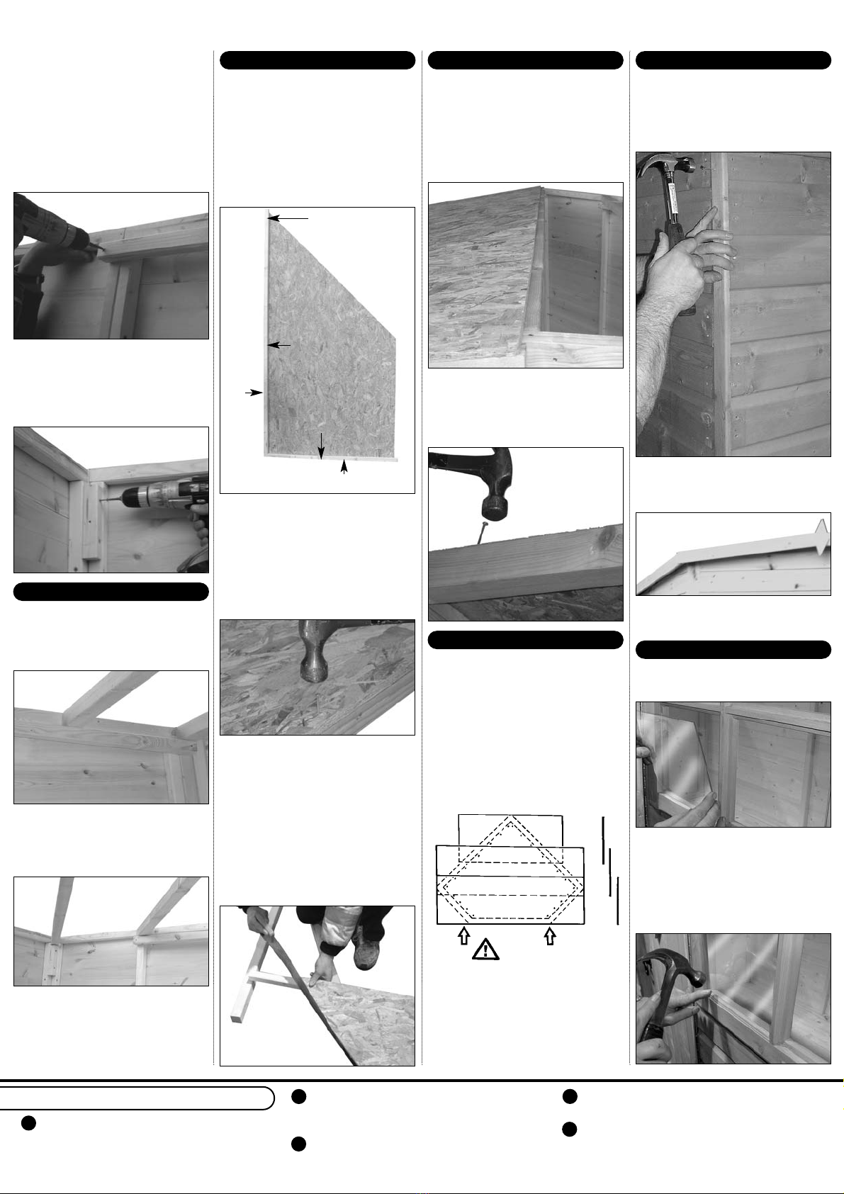
1 Place one large roof section at the
back on one half of the building.
Place the smaller piece in front.
The framework of both sections
should be positioned to go on the
outside of the building. Repeat with
other roof sections.
2 Secure roof to beams and walls
using 40 mm nails - 4 in each beam,
6 in the door section, 3 in each
window panel and 6 in each side.
I- Fit Roof
1 Coverstrips 'I' are fitted at the two
corners where the window panels
meet the sides and where both side
panels meet. Secure using 4x 40
mm nails per strip
2 Fit profiled cover strips where front
meets window panels. Secure using
4x 40mm nails per strip.
3 Fit diamond 'K' where facia joins
above doors using 2x 40 mm nails.
K- Fit Facia, Diamonds & Coverstrips
1 Cut 2 strips of felt measureing 3.42
mtr long. Cut another piece 2 mtr
long. Place the 2 mtr strip at the
back corner and allow an overhang
of felt of approx 50 mm all round.
Place a length 3.42 mtr long
overlapping the existing strip of felt
with the new piece and the final
3.42 mtr piece overlapping this,
leaving approx 50 mm all round.
2 Check that the whole roof felted
and that the overlaps are even.
Secure using 13 mm felt nails
spaced about 75 mm apart, across
the centre of each overlap and all
around the edge of the building.
J- Felt Roof
1 Place a pane of glazing material
'C3' in one aperture.
2 Hold into position with four pieces
of beading 'C4'. The beading may
need to be swapped around to get
the best fit. When satisfied secure
into position using 2x 15 mm panel
pince per piece of beading.
Repeat.
L- Glazing
1 Take one large shaped panel ‘G1’.
Attach piece of framework 1240mm
long ‘G3’. G3 should be flush in the
bottom right-hand corner on the
bottom edge; the opposite end will
overhang. Secure into place using
5x 40mm nails. Note: The picture
shows where the studwork goes
and which panel it should overhang.
2 Attach roof frame ‘G4’, 2137mm
long, flush with ‘G3’ timber; the
opposite end should also overhang.
Secure into place using 7 x 40mm
nails. Repeat with the other large
roof panel ‘G1’. IMPORTANT: make
sure you assemble the mirror image
of the first panel.
3 Take one smll roof triangle panel
‘G2’. Attach piece of framework
1340mm long ‘G3’. Place G3 flush
in the right-angled corner of the roof
panel. Secure with 4x 40mm nails.
Repeat with other small roof panel.
IMPORTANT: make sure you
assemble the mirror image of the
first panel.
Saw off all overhanging
pieces of studwork flush with the
edges of all the roof panels.
H- Construct Roof
4 On the centre framework of one
plain panel in the corner measure
and mark at 78mm. On the outer
frame of the plain panel next to it
mark and measure 78mm. Take
another roof beam support ‘E1’,
position the bottom of the support
on the marks and drill/screw into
position using 2x 60mm screws.
Repeat at other side.
5 In back corner, measure and mark
44 mm from the top. Place the top
of block 'E3' on the mark and
drill/screw into position using 2x 60
mm screws.
1 Take longest support 'F1' and place
back corner to centre of door gable.
The shaped end of the support fits
into the back corner.
2 Take another roof support ‘F2’ and
place on roof beam support at front
and back on one side. Repeat at
other side.
3 Check the building is square. The
gap between roof beams should be
approx. 556mm. Secure beams to
supports using 1x 60mm screw per
beam/support.
G- Fit Roof Beams
Back Corner
Side Panel
Window Panel
G3
G4

Other Shire Outdoor Storage manuals

Shire 6x3 Apex Bike Store No Floor User manual

Shire

Shire 6x3 Apex Bike Store No Floor User manual

Shire Norland Belsoe User manual

Shire

Shire Norland Belsoe User manual

Shire BIKE STORE User manual

Shire

Shire BIKE STORE User manual

Shire 7x5 Value Overlap User manual

Shire

Shire 7x5 Value Overlap User manual

Shire 8x6 Value Overlap User manual

Shire

Shire 8x6 Value Overlap User manual

Popular Outdoor Storage manuals by other brands

Palram CANOPIA RUBICON 6x8 manual

Palram

Palram CANOPIA RUBICON 6x8 manual

OLT Garden Chalet Assembly manual

OLT

OLT Garden Chalet Assembly manual

Riverlea Duratuf KIWI SHEDS MK4C Assembly instructions

Riverlea

Riverlea Duratuf KIWI SHEDS MK4C Assembly instructions

Rubbermaid 5L40 manual

Rubbermaid

Rubbermaid 5L40 manual

ABSCO SHEDS CYCRK Assembly & instruction manual

ABSCO SHEDS

ABSCO SHEDS CYCRK Assembly & instruction manual

STILLA Birch 6x3 Assembly instructions

STILLA

STILLA Birch 6x3 Assembly instructions

Riverlea DURATUF Sentry SL2015 Assembly instructions

Riverlea

Riverlea DURATUF Sentry SL2015 Assembly instructions

SmartStore SS2010 Assembly instructions

SmartStore

SmartStore SS2010 Assembly instructions

Westmann COVER-IT WMCRT86 manual

Westmann

Westmann COVER-IT WMCRT86 manual

Duratuf Kapiti Assembly instructions

Duratuf

Duratuf Kapiti Assembly instructions

Forest garden 8 x 6 T & G SHED manual

Forest garden

Forest garden 8 x 6 T & G SHED manual

Décor et Jardin 62243S801 Assembly Notice

Décor et Jardin

Décor et Jardin 62243S801 Assembly Notice

Suncast Everett BMS6510 Assembly instructions

Suncast

Suncast Everett BMS6510 Assembly instructions

Jimmy at work SPR10009 owner's manual

Jimmy at work

Jimmy at work SPR10009 owner's manual

Lifetime 60280 Assembly instructions

Lifetime

Lifetime 60280 Assembly instructions

Safavieh Outdoor Oliveira PAT7709 quick start guide

Safavieh Outdoor

Safavieh Outdoor Oliveira PAT7709 quick start guide

Arrow Storage Products EPA104 Owner's manual & assembly guide

Arrow Storage Products

Arrow Storage Products EPA104 Owner's manual & assembly guide

Arrow SCG1012CC Series Owner's manual & assembly guide

Arrow

Arrow SCG1012CC Series Owner's manual & assembly guide

manuals.online logo
manuals.online logoBrands
  • About & Mission
  • Contact us
  • Privacy Policy
  • Terms and Conditions

Copyright 2025 Manuals.Online. All Rights Reserved.