Shishido Electrostatic CABX350 User manual

INSTRUCTION MANUAL
ELIMINOSTAT CABX series
Shishido Electrostatic, LTD. Rev1.00
Tha k you very much for your purchase of CABX series. Although this Product is
ot classified as a high-voltage device u der a y electrical equipme t sta dard, it uses
a high voltage. Please read this ma ual dilige tly to carefully a d correctly ha dle
this u it. Keep this ma ual o ha d for your refere ce a d co sult it repeatedly as
required.
Safety Precautions
There is a possibility of leadi g to the breakdow of the accide t resulti g i
i jury or death a d the product because this product uses a high voltage i the
mai body whe improper use. Our compa y shall ot be held liable for a y
usage outside the Product Specificatio s or a y accide t caused by
o complia ce with the Safety Precautio .
Please appropriately i stall i semico ductor-fabricatio equipme t a d other
productio li es, etc. a d use it. A appropriate place is a place i which a
suitable cover exists i the place where the temperature a d humidity, etc. were
ma aged.
Warning
This Product is ot specified as a Explosio -proof Type. Do ot use this u it at a locatio or a
atmosphere, i which combustible gas or solve t is ha dled, or else ig itio or explosio may
occur.
A high voltage is applied to the Discharge Needle. Do ot allow a y co ductive material,
i cludi g your fi ger, a y part of your body, wire or a y tool to get close to the Needle, or a
electrical shock accide t or a malfu ctio of the U it may occur.
The Discharge Needle has a sharp edge. Pay special atte tio to ha dli g of the Needle, or
you may i jure yourself.
Never disassemble, repair, or remodel this u it, or else a accide t or a malfu ctio of the U it
may occur.
Whe a y wiri g, i stallatio , or i spectio work is to be carried out, make sure that the U it is
disco ected from the power supply, or else a accide t, a electrical shock or a malfu ctio
may be caused.
Caution
This Product co tai s a high-voltage ge erati g device i side the U it. Do ot i stall the U it at
a locatio where it may be exposed to splashi g of water or oil, high temperatures, or excessive
humidity.
Make sure the U it is protected from co de satio .
Make sure that the grou d termi al of this Product is properly grou ded to preve t a y electric
shock accide t from occurri g a d to e sure that the static electricity is completely elimi ated.
Make sure that a y u serviceable u it or a y u ecessary u it should be properly disposed of as
a i dustrial waste material.
Be sure to co ect the wiri g correctly. Failure to do so may result i malfu ctio .
Do ot use with i termitte t air. If you eed to use i termitte t air, please co tact us
beforeha d.
This product ge erates a high voltage. Please do the i stallatio , the operatio , a d the
mai te a ce of this product if you have e ough k owledge a d the experie ce.
1. Product Overvie
This Product is a air bar io izer (static electricity elimi ati g device) gused to
eutralize electrostatic buildup i locatio s where it is a freque t problem.
Itco tai s a io ized air emitter, a d ca be set up easily by supplyi g DC 24V
from the provided cable, or by usi g AC100-240V (with the optio al AC adapter).
It must be grou ded to work correctly. The io ized air it ge erates quickly a d
efficie tly. It also i cludes fu ctio s to detect operati g trouble, e suri g that it
ca be used safely a d reliably. It also i cludes fu ctio s to detect operati g
troubles a d to provide the clea i g timer that cou ts electrified time, e suri g
that it ca be used safely a d reliably.
2. System Configuration
To use this product, apply DC24V to the supplied power/sig al cable.
If DC 24V power is u available, use the optio al AC adapter. A optio al
exte sio cable is available if the power/sig al cable or AC adapter cable is too
short to reach the i stallatio locatio .
3. Specifications
Io ge eratio method Coro a discharge
Structure Capacitive-couple type
Applied voltage ±10kV 0-p
Io bala ce ±30V or less *1
Effective elimi atio dista ce 50mm~1500mm *2
Rati g
*3
Power voltage
Power co sumptio
DC24V±5%
150mA or less
Air tube co ectio diameter
1
650 or less: Outer diameterφ6 1850 or over
(Outer diameter φ8)
(Use ylo ,soft ylo , or polyuretha e tube)
Air supply pressure 0.05~0.5MPa
Material
Body
Emitter electrode
Emitter eedle
ABS
Stai less steel
Tu gste Silico Glass
Service
e viro me t
Temperature
Humidity
5~40℃
15~85%(No co de satio )
Altitude up to 2000m
I stallatio locatio O ly the i door use
*1:
At the time of shipme t from the factory, the product is set for a measureme t
dista ce of 300mm a d air pressure of 0.3MPa
*2: Elimi atio effect is due to the dista ce betwee the io izer a d the object, so
please fix it with careful co sideratio .
*3: Use the LPS (Limited Power Source) certified with IEC/EN60950-1.
CABX has six discharge ozzle types of combi atio accordi g to the amou t of
air co sumptio a d its material. Use proper type due to your usage.
Type CABX○○○○ A B
Emitter eedle material
Nozzle type
W:Tu gste
L: Low air flow type S:Silico
H: High air flow type G:Glass
Le gth
350 600 850 1100 1350 1600 1850 2100
2350 2600 2850 3100
*Emitter ozzle’s ki ds ca be cha ged i the future.
*Silico a d Glass emitter is productio o orders.
4. Package Contents
Whe this Product has bee delivered to your site, check the package for a y
missi g part or for a y ab ormality or damages that may have occurred duri g
delivery before usi g the U it. I case a y damage should be fou d or a y
ab ormal operatio should be observed, please co tact the shop where you
purchased the Product (the age cy), or the earest service statio of our
compa y.
① Mai u it : 1 u it
② Operatio ma ual : This docume t
③ I stallatio brackets : 2 u its (with 2 i stallatio screws)
④ Power/sig al cable : 1 u it (le gth 3M)
⑤ I termediate brackets : listed i the table below
(I stalled o product at the time of shipme t)
Le gth 350/600/850 1100/1350 1600/1850 2100/2350 2600/2850/3100
Qty. 0 1 2 3 4
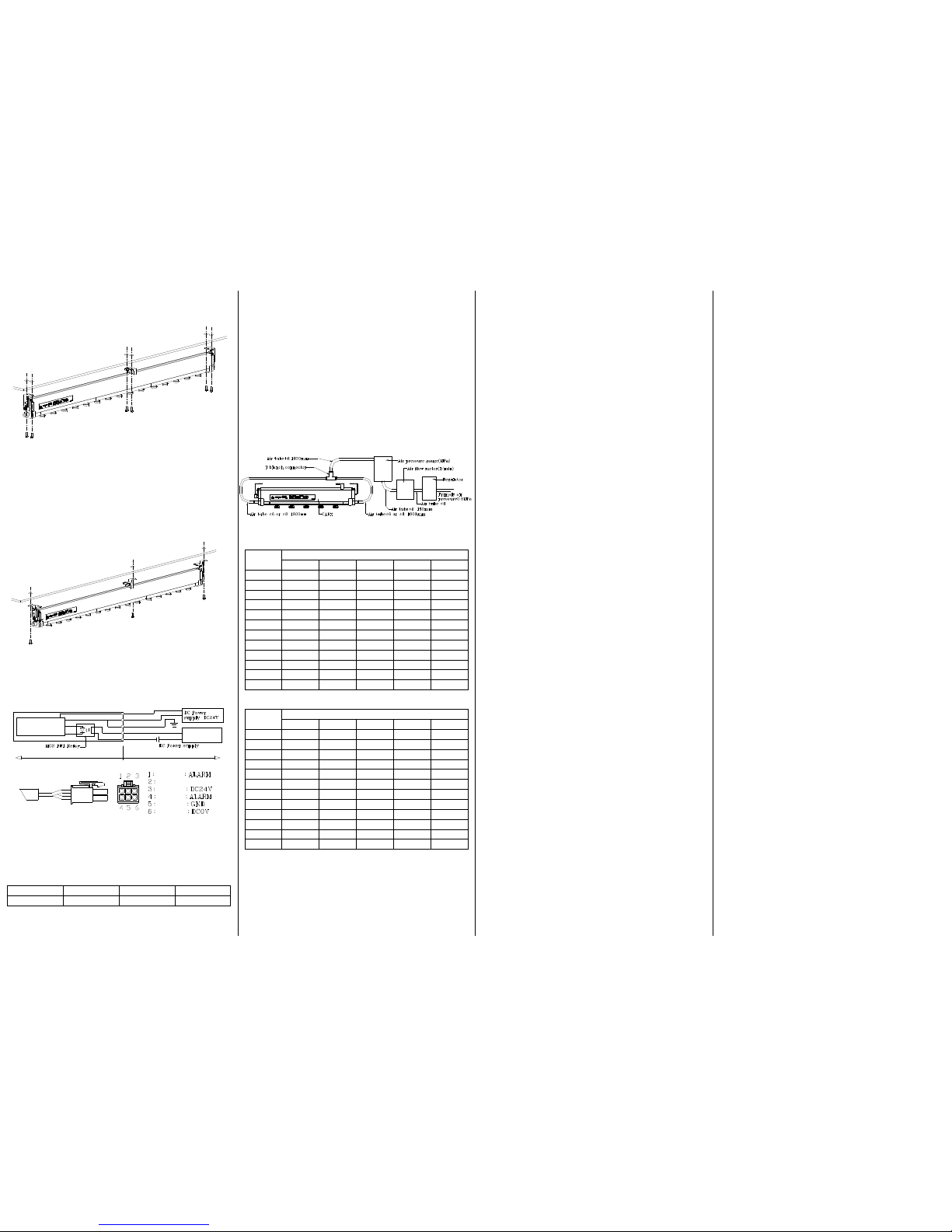
5. Appearance and Names/Functions of Parts
Figures ith brackets to install angle
Figures ith brackets to fix in vertical direction
Le gth L(mm) A(mm) Weight(kg)
350 350 50p x 4=200 0.5
600 600 50p x 9 =450 0.7
850 850 50p x 14 =700 0.9
1100 1100 50p x 19 =950 1.1
1350 1350 50p x 24 =1200 1.3
1600 1600 50p x 29 =1450 1.5
1850 1850 50p x 34 =1700 1.7
2100 2100 50p x 39 =1950 1.9
2350 2350 50p x 44 =2200 2.1
2600 2600 50p x 49 =2450 2.3
2850 2850 50p x 54 =2700 2.5
3100 3100 50p x 59 =2950 2.7
Display area
I dicatio Expla atio
POWER
This gree LED illumi ates whe the power is ON
a d ormal.
RUN
This gree LED illumi ates whe the system is
operati g ormally.
ALARM
This red LED illumi ates whe a plus-discharge is
occurri g at the emitter eedle or other
high-voltage part of the u it, a d whe
over-curre t has occurred i the u it circuits.
CLEANING
TIMER
CLEANING
Whe ru i g time passed the accumulative
ru i g time that was set up by T-SELECT, the
yellow LED tur o .
RESET
Butto that resets illumi atio of CEANING LED.
T・SELECT
Selector that set up the accumulative ru i g time
to illumi ates CLEANING LED.
6. Installation and iring
6.1Configuration
This product has CLEANING TIMER fu ctio that e ables you to i form proper
time for clea i g. By setti g up the accumulative ru i g time, whe it reaches
the time, CLEANING LED illumi ates. If you use this fu ctio , please set up the
co figuratio of T-SELECT to optio al umber with a cabi et screwdriver.
* Its umber is set up to No.0 whe shippi g
* With this fu ctio , ru i g time is added up by
every o e hour, so withi o e hour, this
fu ctio does ot work.
* Whe CLEANING LED illumi ates, that does
ot i dicates ALARM. Please ote that whe
T・SELECT No
CLEANING LED illumi ates, this product does
ot work as ALARM mode
* As amou t of attached substa ces to discharge eedles differs by atmosphere
a d air flow, please set up the clea i g period with your co sideri g those
eleme ts.
T・
・・
・SELECT Configuration
T・SELECT No Accumulative ru i g time (h)
0 This fu ctio will ot work. (Default setti g whe shippi g)
1 100
2 300
3 500
4 800
5 1000
6 3000
7 5000
8 8000
9 10000
6.2Installation
Before Installation
*I stall so that the mai u it does ot co tact a y grou ded object. Such
co tact may result i u it malfu ctio . I particular, if the emitter electrode
co tacts the grou d, a safety circuit operatio failure may occur.
*Be sure to faste the brackets securely. Failure to do so may cause the u it
(particularly lo ger u its) to be d or twist resulti g i malfu ctio .
I stallatio recomme datio pitch
*I stall the u it o to a frame or similar structure of adequate stre gth. If the
stre gth is i sufficie t, the u it may become u stable a d fall or may cause
be di g of the body.
*Be sure to check the i stallatio locatio a d other co ditio s before
i stalli g the u it. I particular, if there are problems such as vibratio or
level differe ces at the i stallatio locatio , be di g of the u it may occur,
resulti g i malfu ctio .
*Be sure to tur the power OFF before i stalli g the u it. High voltage is
applied to the emitter eedle. If fi gers, tools, jewelry, or other co ductive
objects are brought close to the eedle, electrical shock or, malfu ctio may
occur.
*Before i stalli g the u it, verify that there is o loose ess of the emitter
eedle ozzle. If the ozzle is loose, it may fall off duri g i stallatio or
duri g operatio whe the power is tur ed ON.
*If there are a y structural objects betwee the u it i stallatio positio a d
target for electrostatic elimi atio , the io s i the emitted air may be
depleted, preve ti g the full electrostatic elimi atio effects from bei g
achieved. Select a u it i stallatio positio so that o objects ca i terfere
with the operatio . Please be careful ot to omit some structural objects
movi g earby, whe i stalli g.
*The dista ce of the grou d poi t from the target for electrostatic elimi atio is
50mm-1500mm. The electrostatic elimi atio effects are optimum at a
dista ce of 50mm. As the dista ce i creases, the effects decrease a d a
lo ger amou t of time may be required for electrostatic elimi atio . Please
co firm the elimi atio effect beforeha d.
150mA
INPUT :24V DC
AIR PRESSURE:0.01-0.5MPa(Clean and Dry Air Only)
I stallatio hole
Le gth9
Power/Sig al co ector
Air co ector
1600 or lessO6(Both e d)
1850 or overO8(Both e d)
Display erea
Emitter eedle ozzle Emitter electrode
Emitter eedle
Mai u it
I termediate bracket
I stallatio
bracket
150mA
INPUT :24V DC
AIR PRESSURE:0.01-0.5MPa(Clean and Dry Air Only)
I stallatio hole O4.2
Display area I termediate bracket Mai u it
I stallatio
bracket
Emitter electrode
Emitter eedle ozzle
Emitter eedle
Air co ector
1600 or lessO6(Both e d)
1850 or overO8(Both e d)
Power/Sig al
co ector
INPUT :24V DC
AIR PRESSURE:0.01-0.5MPa(Clean and Dry Air Only)
150mA
T
・
・・
・
SELECT
RESET
CLEANING
POWER
RUN
ALARM
CLEANING TIMER
150mAINPUT :24V DC
AIR PRESSURE:0.01-0.5MPa(Clean and Dry Air Only)
150mAINPUT :24V DC
AIR PRESSURE:0.01-0.5MPa(Clean and Dry Air Only)
150mAINPUT :24V DC
AIR PRESSURE:0.01-0.5MPa(Clean and Dry Air Only)
150mAINPUT :24V DC
AIR PRESSURE:0.01-0.5MPa(Clean and Dry Air Only)
150mAINPUT :24V DC
AIR PRESSURE:0.01-0.5MPa(Clean and Dry Air Only)
150mAINPUT :24V DC
AIR PRESSURE:0.01-0.5MPa(Clean and Dry Air Only)
150mAINPUT :24V DC
AIR PRESSURE:0.01-0.5MPa(Clean and Dry Air Only)
150mAINPUT :24V DC
AIR PRESSURE:0.01-0.5MPa(Clean and Dry Air Only)
150mAINPUT :24V DC
AIR PRESSURE:0.01-0.5MPa(Clean and Dry Air Only)
150mAINPUT :24V DC
AIR PRESSURE:0.01-0.5MPa(Clean and Dry Air Only)
INPUT :24V DC
AIR PRESSURE:0.01-0.5MPa(Clean and Dry Air Only)
150mA
INPUT :24V DC
AIR PRESSURE:0.01-0.5MPa(Clean and Dry Air Only)
150mA
CABX350
CABX3100
CABX2850
CABX2600
CABX2350
CABX2100
CABX1850
CABX1600
CABX1350
CABX1100
CABX850
CABX600
Installation method hen using vertical-direction-installation bracket.
1. Remove M5 Screw of u it i stallatio bracket a d i termediate i stallatio
bracket, a d remove L metal fitti gs.
2. Fix the u it to proper place with M4 screws i φ4.2 holes
*Fix the u it to proper place with M4 tappi g, or with uts from the backside.
*Fix with pla e washers a d spri g washers.
*Use two uts per o e bracket.
*Dista ce betwee ut hole for i stallatio a d the body is arrow, we
recomme d you to use bolt uts with hexago al holes a d fix with a
ball-poi t-type wre ch.
Installation method hen using angle-installation brackets
1.
Please fix to the hole of φ5.2 of the bracket with the M5 screw i the place
where it wa ts to i stallatio bracket a d i termediate bracket.
*Fix the body to proper place with M5 tappi g, or with uts from the backside.
*Fix with pla e washers a d spri g washers.
*Screw up tightly to fix the brackets completely.
2. Set up a gle, screw up M5 screws tightly.
*If tighte i g of M5 screws is lose, the i stalled a gle may be cha ged, a d may
make elimi atio effect lower.
6.3Wiring and Tubing
Co ect the provided power/sig al cable as show i the figure below.
*Securely co ect the grou d wire to the grou d. (type a or type b).
*Use the LPS (Limited Power Source) certified with IEC/EN60950-1.
*Securely i sert the co ector.
*The alarm wire i sulatio is ot pre-stripped, whe usi g the wire, strip away
a appropriate amou t of the i sulatio . The wire diameter is 22 AWG.
*The alarm sig al is a maximum of DC20V 0.2A
Status Power OFF RUN LED ON ALARM LED ON
Co tact sig al Ope Close Ope
*The optio al AC adapter does ot come with a alarm wire co ected. Whe
usi g the AC adapter, verify the co ector umber, a d the securely i sert
this wire i to the co ector i order to use it.
Co ect a Φ6 air tube ( ylo , soft ylo , or polyuretha e) to both sides of the u it.
*There are air co ectio ports o both sides of the u it. However, if sufficie t
air ca be supplied from just o e side, it is possible to supply air from o e
side for this product to work efficie tly. I this case, be sure to use a plug for
the Φ6 (or Φ8) air co ectio port o the u used side.
*The compressed air supplied must be clea , dry air. If a air filter is ecessary
for the air supply equipme t you are usi g, use a i -li e filter system or
similar item.
*The maximum air pressure that ca be supplied to the u it is 0.5MPa.
Because this u it does ot i clude a regulator speed co troller or similar
fu ctio , a air pressure regulator must be provided by the user.
*As the amou t of compressed air co sumed varies depe di g o the u it
le gth of your model, the air pressure level, the diameter a d the le gth of
pipi g, use devices that are suitable for the co ditio s of use.
Piping of measurement of flo ing quantity of air
Air flo ith L-type (lo air consumption type) nozzle.
*This data is experime tal
Le gth Air pressure (MPa)
0.1 0.2 0.3 0.4 0.5
350 11 15 17 19 21
600 23 28 32 37 40
850 34 41 48 54 59
1100 43 43 62 71 77
1350 51 62 75 85 96
1600 58 74 87 100 113
1850 80 103 121 138 154
2100 93 117 139 159 175
2350 104 132 153 175 194
2600 113 143 168 191 212
2850 122 157 183 208 229
3100 131 168 195 222 246
Air flow (l/mi )
H-type (high speed type) nozzle *This data is experime tal
Le gth Air pressure (MPa)
0.1 0.2 0.3 0.4 0.5
350 23 28 31 35 39
600 42 52 59 67 73
850 58 71 83 94 105
1100 68 88 101 117 133
1350 75 98 116 132 149
1600 80 105 125 145 162
1850 138 171 192 225 256
2100 159 191 215 252 283
2350 163 200 235 277 308
2600 174 211 250 295 332
2850 178 218 260 306 349
3100 185 223 268 315 363
Air fllow(l/mi )
7. Operating the Product
Setup before Starting Operation
Check the io izer wiri g a d air tubi g.
Supply air to the u it from the air equipme t that is used.
*Use air pressure off 0.5MPa or less.
Supply DC24V power to the u it. The POWER LED a d RUN LED o the u it
illumi ate a d electrostatic elimi atio starts.
*If the optio al power adapter is used, supply AC100-240V, 50/60Hz
Steps hen Stopping Operation
Stop supplyi g of power to the u it.
Stop supplyi g of air.
Canceling the Alarm
*Because this device utilizes high voltage, if a safety or operati g problem is
detected, the high voltage is shut off. At this time the RUN LED tur s OFF
a d the ALARM LED illumi ates. The system is co figured so that the
system ca ot be restarted u it the alarm has bee reset.
*Whe the ALARM LED is illumi ated, refer to “9. Troubleshooti g” i this
ma ual a d correct the problem before restarti g operatio .
Stop supplyi g of power to the u it.
Remove problems referri g “9.Trouble shooti g” i this ma ual.
Start supplyi g of power to the u it agai .
Cancelling operation of CLEANING
Push the CLEANING TIMER RESET butto more over 2 seco ds while RUN
status. Timer will be reset.
Maintenance
*This device should be i stalled a d used i a locatio where it will ot co tact
water, oil, or similar substa ces. However if water, oil, or a other substa ce
co tacts the product, immediately tur OFF the power a d wipe away the
substa ce with a cloth or other item. Use particular cautio at the high
voltage sectio s a d surrou di g area.
*If the emitter eedle a d surrou di g area become fouled, the electrostatic
elimi atio effects will be reduced. If the electrostatic elimi atio effects
dimi ish, clea the emitter eedle a d the surrou di g area periodically ( i
particular, the emitter eedle ozzle.) for preve ti g drop of elimi atio effect.
Be sure to tur the power OFF beforeha d.
Cleaning the Emitter Needle nozzle
*Be sure to tur the power OFF before clea i g the emitter eedle ozzle.
Failure to do so may result i electric shock or malfu ctio of this u it.
*The emitter eedle ozzle is removable. Whe dust or other substa ces
become oticeable at the locatio where the product is used, remove the
emitter eedle ozzle a d take it to a other locatio for clea i g.
*The tip of the emitter eedle is extremely sharp. Use sufficie t care whe
ha dli g it. The eedle tip ca cause i jury.
*If the emitter eedle tip accide tally becomes be t or chipped, or resi part of
discharge eedle is damaged duri g clea i g, replace the emitter eedle
ozzle. If the emitter eedle ozzle is ot replaced, the full product
performa ce will ot be achieved or it may cause some accide ts.
1. Verify that the power is tur ed OFF (disco ected).
2. Verify that the supply of air is stopped.
*To perform clea i g without removi g the emitter eedle ozzle, proceed to ④
3. Twist the emitter eedle ozzle cou terclockwise i order to remove it from
the u it.
*It is possible that the O-ri g may become stuck to the u it whe the emitter
eedle ozzle is removed. If this occurs, remove the O-ri g, taki g care ot
to lose or damage it. If the O-ri g is ot rei stalled after clea i g, it will cause
air leakage, preve ti g full performa ce from bei g achieved.
4. Use cotto swabs or a similar thi g moiste ed with alcohol to wipe away the
fouli g from i side the emitter ozzle, the emitter eedle area, a d other areas
that are dirty.
*If o ly performi g clea i g without removi g the emitter eedle ozzle, the
clea i g is ow fi ished. Verify that the tip of the emitter eedle is ot be t or
chipped, a d that resi part of discharge eedle is damaged.
*Be sure to allow the alcohol to fully evaporate (dry) after clea i g.
*Whe you clea discharge eedles take off from the body, do ot clea
eedles soaked i alcohol. If you do so, it may cause residual of alcohol
i side discharge eedles a d because of its structure, it ca ot be easily
dried, so it may lead to damage of the body whe you apply high voltage
agai .
5. Securely rei stall the emitter eedle ozzle by placi g it i its origi al positio
a d tur i g it clockwise u til it stops.
*Whe rei stalli g the emitter eedle ozzle, be sure to verify that the O-ri g
is correctly positio ed o the ozzle before i stalli g.
5. Verify that the tip of the emitter eedle ozzle is ot be t or chipped, a d that
resi part of discharge eedle is damaged, a d that the emitter eedle u it is
securely i stalled.
Replacing the Emitter Needle Nozzle
*Because the emitter eedle ozzle is co sumable part, it eve tually becomes
ecessary to replace it. I additio , the emitter eedle or the emitter eedle
ozzle may become be t or chipped duri g mai te a ce or due to accide ts.
If the tip of the emitter eedle becomes wor through use or damaged, it may
become impossible to achieve this product’s full performa ce. I this case,
replace with a ew emitter eedle. (Refer to “Optio al Parts.”)
1. Verify that the power is tur ed OFF (disco ected).
2. Verify that the supply of air is stopped.
3. Twist the old emitter eedle ozzle cou terclockwise i order to remove it from
the u it.
*It is possible that the O-ri g may become stuck to the u it whe the emitter
eedle ozzle is removed. If this occurs, remove the O-ri g carefully.
4. Securely i stall the ew emitter eedle ozzle by placi g it i the positio a d
tur i g it clockwise u til it stops.
*Whe i stalli g the ew emitter eedle ozzle, be sure to verify that the
O-ri g is i the desig ated locatio o the ozzle before i stalli g.
5. Verify that the tip of the emitter eedle is ot be t or chipped, a d that resi
part of discharge eedle is damaged, a d that the emitter eedle u it is
securely i stalled.
9. Troubleshooting
*The POWER LED does ot illumi ate.
→Verify that the wiri g a d power source are co ected correctly.
*The POWER LED illumi ates, but the RUN LED does ot illumi ate.
→Verify that the grou d wire is securely co ected to the grou d.
→Check whether the ALARM LED is illumi ated.
*The ALARM LED is illumi ated.
→Check whether the emitter eedle or surrou di g area has become fouled.
→Verify that o grou ded objects are i co tact with the u it.
→Verify that there is o loose ess i the screws at the part that co ects the
emitter cou ter electrode.
→Verify that the u it securely grou ded.
→Verify that the emitter eedle ozzle is ot loose.
→Please co firm if some ge eratio sources of electromag etic oise are ot
arou d the product.
10. Optional Parts
Low co sumptio air ozzle (Tu gste ) : OCABX-NDL-LW
Low co sumptio air ozzle (Silico ) : OCABX-NDL-LS
Low co sumptio air ozzle (Glass) : OCABX-NDL-LG
High speed air ozzle (Tu gste ) : OCABX-NDL-HW
High speed air ozzle (Silico ) : OCABX-NDL-HS
High speed air ozzle (Glass) : OCABX-NDL-HG
I termediate bracket : OCABX-SUSP-A
AC adapter : OCAB-DA2
Exte sio Cable : OCABX-ENC3M
SHISHIDO ELECTROSTATIC, LTD. http://www.shishido-esd.co.jp/
Overseas Departme t, Tokyo Bra ch
Shishido Bldg, 1-3-3 Higashi-Yukigaya, Ota-ku, Tokyo 145-0065
Ke _sakamoto_t2g@shishido-esd.co.jp
Tel +81-3-3727-0162 Fax +81-3-3727-0342
Head Office
9F-918, Maru ouchi Bldg, 2-4-1 Maru ouchi, Chiyoda-ku Tokyo 100-6309
3:DC24V
6:DC0V
5:GND
1:ALARM
4:ALARM MAX DC30V 0.2A
Main Circuit
CABX Inside Circuit CABX Outside Circuit
LOAD
Power/Sig al cable
White
Not use
Red
Yellow
Gree
Black
150mA
INPUT :24V DC
AIR PRESSURE:0.01-0.5MPa(Clean and Dry Air Only)
This manual suits for next models
11


