Shoreline Lift Mate User instructions
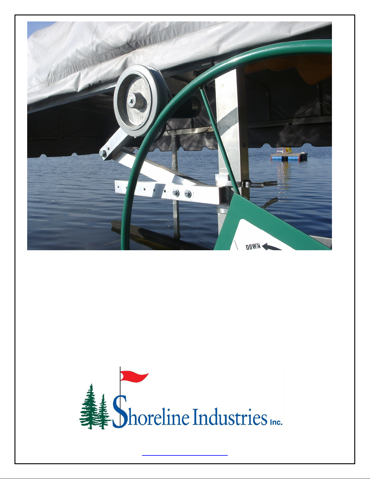
“LIFT MATE”
BOAT LIFT MOTOR
ASSEMBLY
Assembly and Operating Manual
www.boatliftmotor.com
03/26/2010
LIMITED WARRANTY
Shoreline Industries, Inc. warrants its products shall be free from defects in materials and
workmanship for a period of two years from the date of purchase as shown on the customer’s
invoice. Shoreline’s warranty is limited to products purchased new by the original owner and is
not transferable.
SHORELINE WILL AT ITS OPTION REPAIR OR REPLACE, WITHOUT CHARGE, OR
ALLOW CREDIT FOR ANY SUCH GOODS FOUND ON EXAMINATION BY SHORELINE TO
BE DEFECTIVE UNDER NORMAL USE AND SERVICE. THE BUYER’S REMEDIES WITH
RESPECT TO DEFECTIVE GOODS SHALL BE EXCLUSIVELY LIMITED AS ABOVE
PROVIDED AND IN NO EVENT SHALL THE SELLER BE LIABLE FOR INCIDENTAL OR
CONSEQUENTIAL DAMAGES OF ANY NATURE. ALL OTHER WARRANTIES,
INCLUDING BUT NOT LIMITED TO WARRANTIES OF MERCHANTABILITY AND FITNESS
FOR A PARTICULAR PURPOSE ARE EXPRESSLY DISCLAIMED.
Shoreline’s warranty does not cover damage caused by circumstances outside its reasonable
control, including but not limited to, improper use, installation, overloading, accident, neglect or
harmful alterations or repairs made by others.
READ THROUGH THE ENTIRE MANUAL
It is recommended to read through the entire manual before beginning your installation.
Follow all steps exactly.
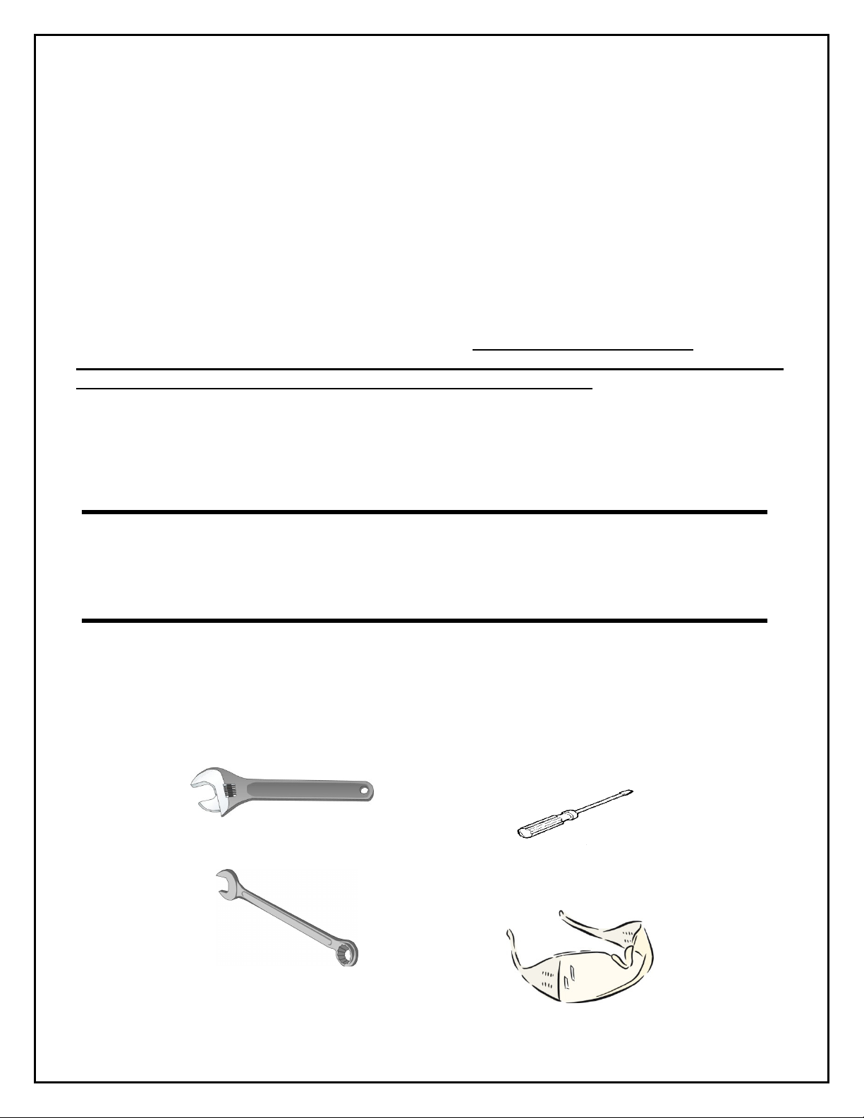
TOOLS NEEDED
Review the tools needed list here on this page. Gather all tools needed for the assembly of your unit
before starting the installation steps.
Adjustable Wrench
5/16” 1/2” and 15/16”
Open End Wrenches
Flat Head Screwdriver
Safety Glasses
2
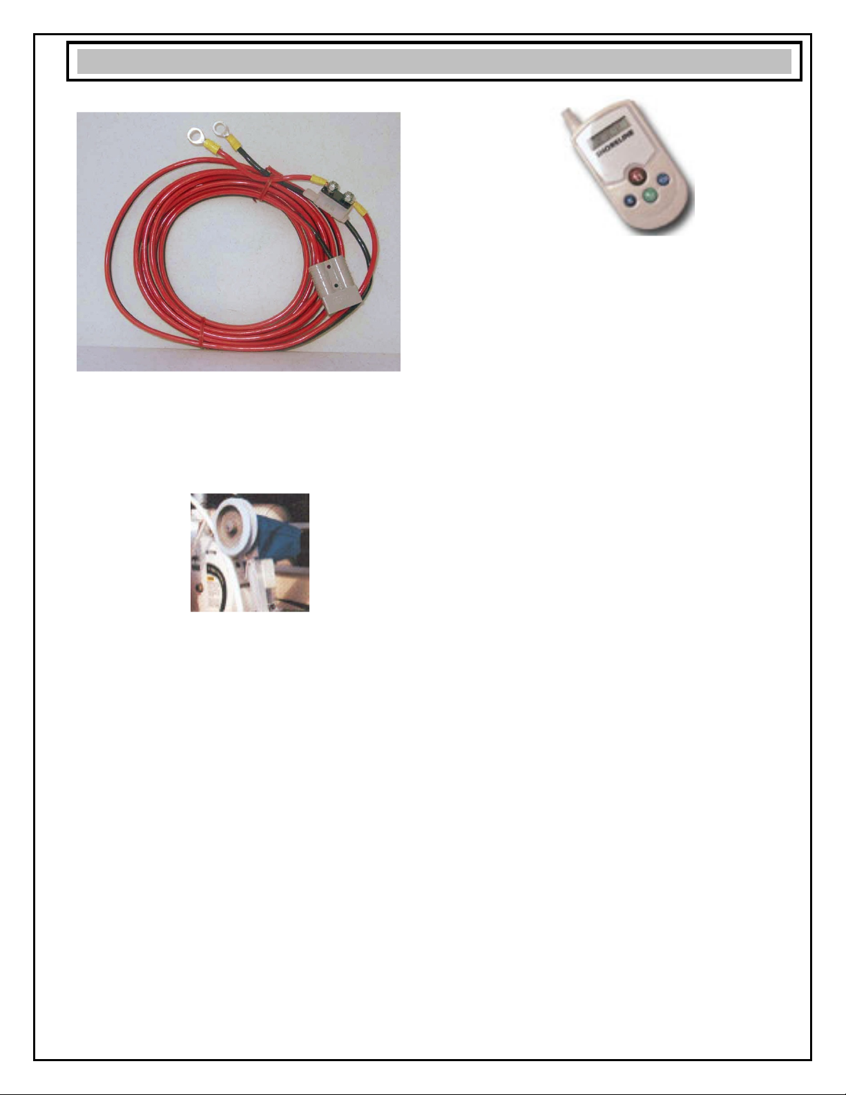
20 FT. BATTERY CABLE
25 FT. BATTERY CABLE FOR PONTOONS
30 FT. BATTERY CABLE FOR PONTOONS
VMC – VINYL MOTOR COVER
Dresses up the motor and matches canopy color.
Available in six colors; burgundy, gray, tan, green,
white & blue.
REMOTE CONTROL ADD-ON KIT
Turns any Lift Mate into a “keyless remote” like
your automobile.
PONTOON KIT
3 ft. wheel extension. Moves the wheel away from
the winch.
TO ORDER
See your local retailer.
3
ACCESSORIES/OPTIONS
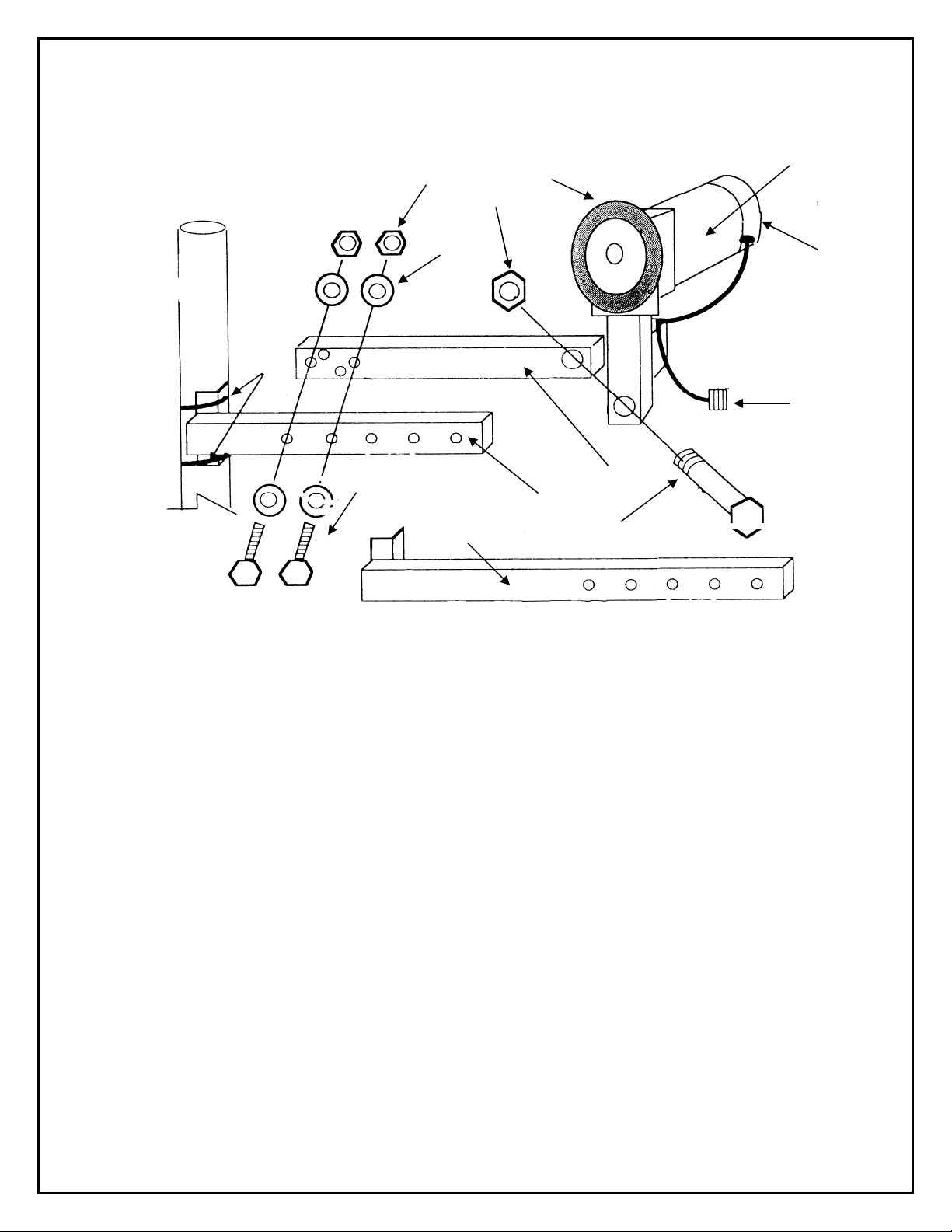
INSPECT SHIPMENT
Your boat lift motor was shipped complete in one
carton. Use care when handling the carton.
Remove all items from your shipping carton. Check
all items against the packing list below. Note any
items lost or damaged in shipment.
Note any damage to the shipping carton. Refer to
the exploded view and parts list in the back of the
manual for the part names and numbers of missing
or damaged items. Call retailer where purchased if
problems exist.
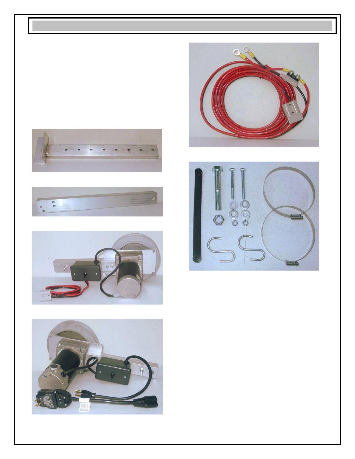
PACKING LIST
●Inner Arm with Bracket
●Outer Arm with Pivot Hole
●12 Volt Electric Motor OR
●110 Volt Electric Motor with GFI Outlet Cord
●15 Foot Battery Cord (12 Volt Motor Only)
●One each Parts Bag Assembly
Containing the following parts:
●One Each 9” Rubber Poly Strap.
●One Each 4 “ x 5/8
”
Hex Head Pivot Bolt.
●One Each 5/8“ Hex Head Pivot Bolt Nut.
●Two Each 31/2” x 5/16” Hex Head Bolt.
●Two Each 5/16
”
Hex Head Nuts.
●Four Each 5/16” Washers.
●Two Each S-Hooks.
●Two Each 5” Metal Band Clamps.
Do not proceed with assembly until you have a
good understanding of part identification.
4
PACKING LIST
PLAN YOUR INSTALLATION
The Lift Mate is designed to mount on most
manufacturers’ boatlifts. As a result of its
compatibility with all lifts, your first task is to review
your particular lift against the assembly instructions
included here.
Review the following bullets. Do not proceed with
the installation until you have a general
understanding of how you are going to install your
unit.
●The Lift Mate mounts onto the winch lift post.
Locate the winch post on your lift.
See Fig. 2 & 3.
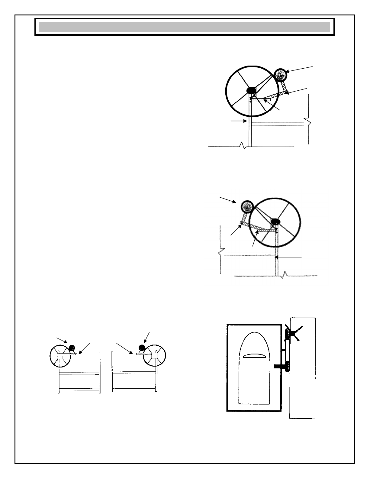
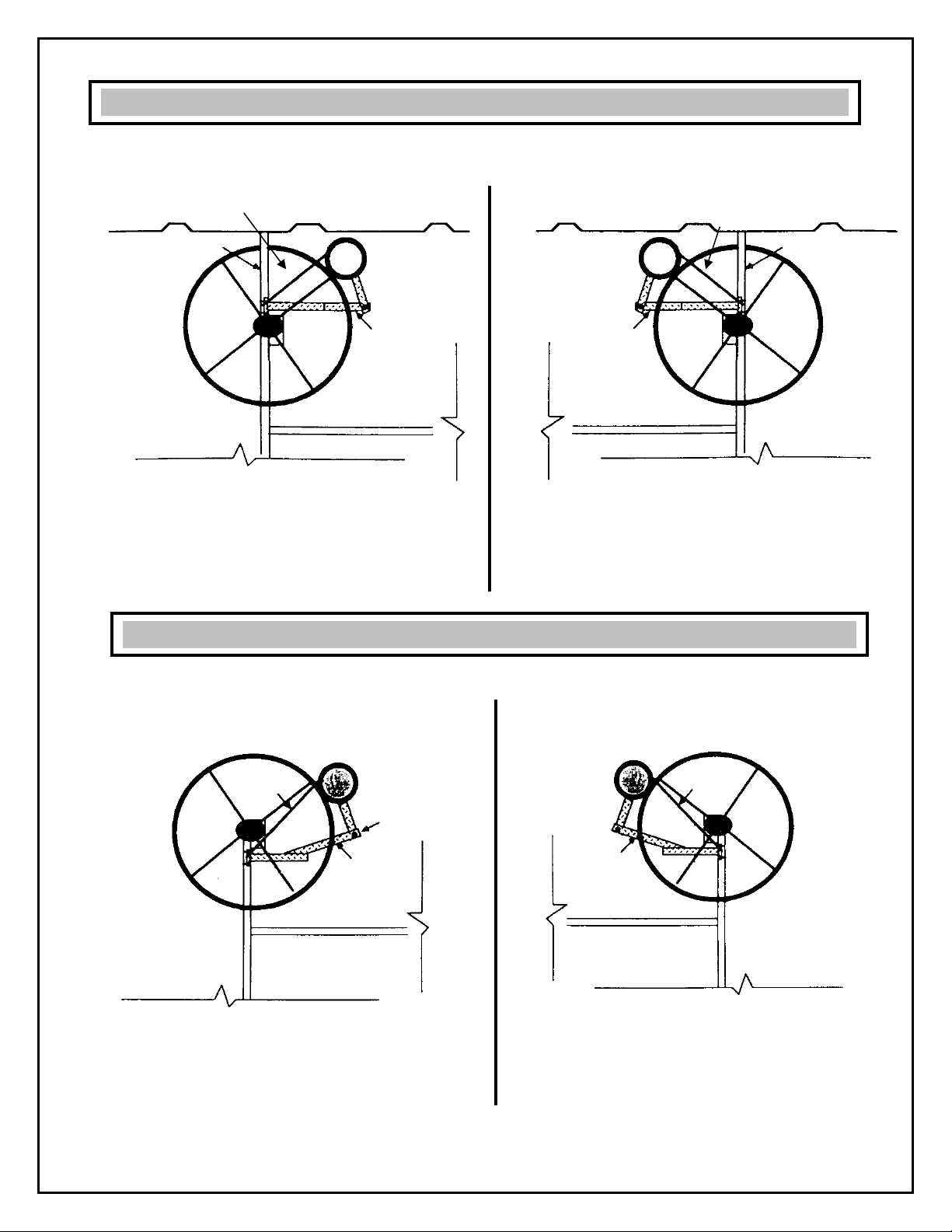
●Stand on your dock in front of your lift. Determine if
your winch lift post is a left mount or a right mount.
See Fig. 2 & 3.
●Note that the Lift Mate motor is mounted so that it
is between the left and right lift posts.
See Fig. 1,2, & 3.
●Also note that the motor rests against the lift wheel
at roughly the 10 or 2 o’clock position. This allows
the weight of the motor to rest against the wheel
and aid in traction. See Fig. 1,2,& 3.
●Note that when properly mounted on the winch
post of the lift, the Lift Mate rubber traction wheel
is closest to the dock and the motor is closest to
the boat. See Fig. 4.
•The motor has two drain holes. The motor is
correctly mounted when the drain holes are on the
bottom side of the motor. Rainwater will seep into
the motor if the motor is mounted with drain holes
on top.
Left Winch Post Right Winch Post
Correct position of lift motor is between the left and right lift
posts in roughly the 10 or 2 O’clock position
As viewed from the dock.
FIG. 1
Left Winch Post Installation
As viewed from Dock
FIG. 2
Right Mount Winch Post Installation
As viewed from Dock
FIG. 3
Correct position of lift motor is when the rubber traction
wheel is closest to the dock and the lift motor is closest to
the boat
5 FIG. 4
Right
Winch
Post
Lift Motor
Lift
Motor
No
Yes
Dock
Boat
Lift
Motor
Lift
Motor
PLAN YOUR INSTALLATION
Inner Arm
Inner Arm
Inner Arm
Left
Winch
Post
Outer Arm
Outer
Arm

FIG 6: Left Winch Post Installation View
FIG. 8: Left Winch Post Installation View
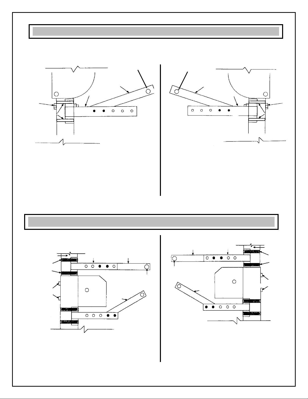
INSTALL INNER ARM
1. Determine which type of mount you have—a left
post install or a right post install. Then refer to the
left or right install photos as you are installing the
arm.
2. Mount the inner arm with bracket to the winch
post. In this case it is just above the winch box. See
Figs. 6 or 7 depending on which type of post mount.
NOTE: The position of the inner arm will vary
from lift to lift. Refer to the miscellaneous
drawings/photos on pages 11-13 for specific arm
positions on the different types of lifts on the
market today.
FIG. 7: Right Post Winch Post Installation
FIG. 9: Right Winch Post Installation
3. Fasten the inner arm with the two band straps
over the angle bracket. Mount one band strap on top
of bracket. Mount the other band strap on bottom of
bracket. See Figs. 8 or 9.
4. Tighten just enough to hold bracket in place.
Further adjustment will occur in a later step.
6
Inner Arm Inner Arm
Band Strap
Band Strap
Band Strap
Band Strap
STEP 1: INSTALL INNER ARM WITH BRACKET ONTO WINCH POST
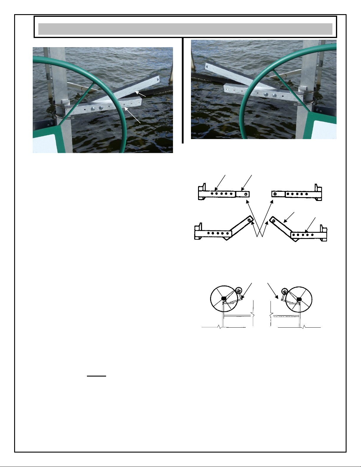
FIG 10: Left Winch Post Installation View
INSTALL OUTER ARM
The outer arm can be installed in a variety of
configurations. See Fig 12. The outer arm is the
transition piece between the inner arm and the lift
motor. In the next step, you will mount the lift motor
in roughly the 10 or 2 o’clock position. The outer arm
position will dictate the lift motor’s final position
against the wheel.
Note: There may be some trial and error that
occurs during this step and the next one.
1. Review Fig. 12. The outer arm can bolt on in a
variety of positions. The end goal is to mount the lift
motor arm (next step) onto this arm and have the
motor’s rubber wheel touching the lift wheel at
roughly the 10 or 2 o’clock position.
Note: On some installs, the arm may need to be
positioned downward so the motor is mounting
in the 2 or 4:00 o’clock position.
2. View the miscellaneous drawings/photos on
pages 10-12 for specific arm positions on the
different types of lifts on the market today. By
utilizing the nine holes in both the inner arm and
outer arm, you can adjust the length and angle
positioning of the arms to fit almost any boatlift. The
4 holes in the outer arm will place the outer arm at
15º or 45º.
3. Bolt the outer arm behind and to the inner arm
using the (2) 5/16” x 3 1/2” bolts, nuts, and washers.
See Fig. 10. The pivot hole on the outer arm should
be at least 3”, but not more than 8” from the outer
edge of the winch wheel.
Note: On some installs, the outer arm may need
to go in front of the inner arm. If your boat lift
requires a shorter arm length than our standard
holes allow, drill (2) 5/16” holes where needed in
and lowering the arms will help.
FIG 11: Right Winch Post Installation View
Left Winch Post
Right Winch Post
Installation View Installation View
FIG. 12
The Outer Arm can be installed in many configurations. The
outer arm is the transition piece between the inner arm and
the lift motor. In the next step, you will mount the lift motor in
roughly the 10 or 2 o’clock position. The outer arm position
will dictate where the lift motor’s final position will be.
FIG. 13
7
Outer
Arm
Inner
Arm
Outer
Arm
Inner
Arm
Inner
Arm
Outer
Arm
Outer
Arm
Inner
Arm
STEP 2: INSTALL OUTER ARM ONTO INNER ARM
Pivot
Hole

INSTALL MOTOR ARM
1. Run the 5/8” pivot bolt thru the pivot hole in the
motor arm with threads away from dock.
See Fig. 14.
2. Run the 5/8” bolt thru the pivot hole in the outer
arm and lightly screw on 5/8” nut. See Fig. 14. The
motor arm should be in front of the outer arm.
See Fig. 14.
3. Rotate the motor up and over the pivot so motor’s
rubber traction wheel rests on the boat lift wheel.
See Fig. 14.
4. The lift motor’s rubber traction wheel should be
touching the lift wheel at roughly the 10 or 2 o’clock
position. See Fig. 14. If the motor is not positioned
correctly review Step 2: Install Outer Arm Onto The
Inner Arm on the previous page. Adjust the angle of
the outer arm until the motor rests near the 10 or 2
o’clock position on the lift wheel. See Figs. 12 & 13.
5. Firmly tighten the band clamps on the winch post.
using a 5/16” wrench. See Fig. 14.
Note: Lift up on the arms while tightening the
band clamps. This will allow you to firmly
tighten the clamps.
6. Tighten the 5/8” nut until it just touches the back
side of the outer arm. See Figure 15.
Note: Do not over tighten the nut. The wheels
will not align if over tightening occurs.
Note: Each boat lift will have a different sized
space at the pivot point. Some lifts will have no
space. See Fig. 15. Even if there is some space
between the motor arm and the outer arm where
it pivots, the grooved rubber traction wheel
should follow the boat lift wheel and not jump
off. If you feel you need spacers, purchase large
nylon washers at your local hardware store and
place them between the arms and over the pivot
bolt.
6. Hook one end of the black rubber poly strap into
the top hole of the motor plate towards the winch
post. Fasten the other end to the open end of the
inner or outer arm or directly onto the winch box.
See Fig. 16.
Note: Black rubber poly strap fits most but not
all applications. Alternates may be purchased at
your local hardware store.
FIG. 14
FIG. 15
8
FIG. 16
Rubber
Wheel
Band
Straps
Motor
Arm
Pivot
Bolt
Motor
Arm
Space
Between
Arms
Outer
Arm
5/8”
Nut
Motor
Plate
Rubber
Poly
Strap
STEP 3: INSTALL MOTOR ARM ONTO OUTER ARM
Pivot
Bolt
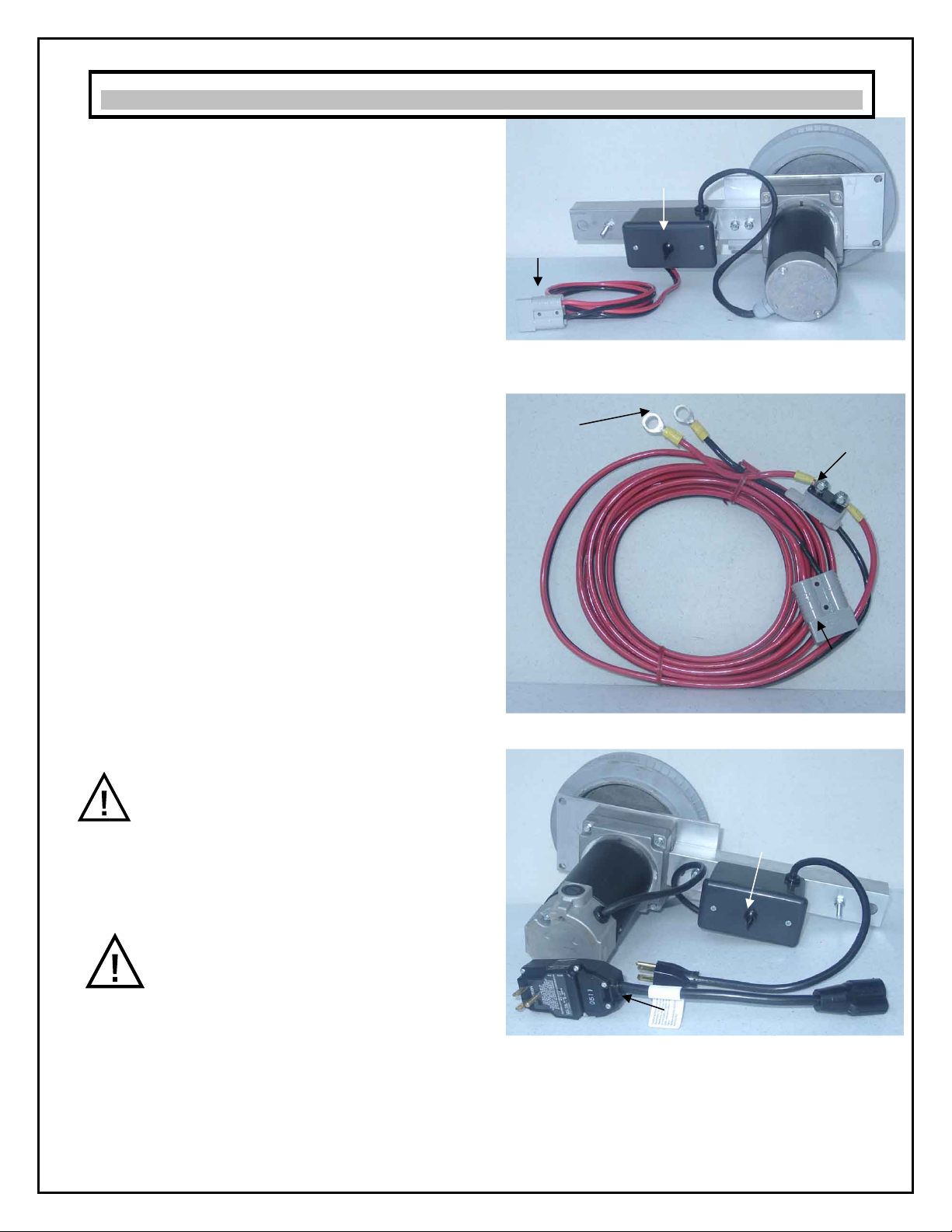
FIG. 16
12 VOLT BATTERY WIRING:
We recommend that you hook the harness to the
boat battery on the 12 volt Lift Mate. The boat motor
is charging the battery all the time. It is unlikely that
the lift motor would drain the battery so you cannot
start your boat. Some use a separate 12v battery on
the dock. Try to hide the 15’ cable in the boat by
running it along the side channels, or below the
seats, or under the pontoon deck, or under the
carpet. See Fig. 17 & 18.
Longer cables (pontoon kits) are available at
Shoreline Industries. Refer to the parts list in the
back of the manual, the options list in the front of the
manual, or call your local retailer.
Mate the two plastic quick connects and lightly
attach the two lead ends (one with a circuit breaker
attached) to the battery poles. See Fig. 18. Flip the
motor switch “up” to see that the lift wheel rotates in
the “up” direction. If not, reverse the leads at the
battery and tighten down. See Fig. 17 & 18.
Note: The 12 volt motor is reversible by just
changing the leads at the battery.
The 60 AMP circuit breaker is attached to one of the
lead ends for safety. See Fig. 18. This breaker must
attach to the + pole.
110 VOLT WIRING
This unit uses a 110 volt 15 amp service. Make sure
the unit is connected to an outlet having the same
configuration as the plug. No adapter should be
used with this unit.
Caution: Before plugging in your unit
make sure it will be connected to a
supply circuit that is protected by a
circuit breaker.
Check with a qualified electrician if the grounding
instructions are not completely understood or you
are in doubt as to whether the motor is properly
grounded.
Caution: Always properly connect and
ground your unit. An improper
connection can cause an electrical
shock resulting in severe injury or
death. If you are unsure of the proper electrical
connections or grounding procedures, contact a
qualified electrician to perform the installation.
To reduce the risk of shock, this unit is equipped
with a ground fault interrupter (GFI) plug. See Fig.
19. The GFI plug must be plugged into a matching
outlet that is properly installed and grounded in
accordance with all local codes and ordinances.
FIG. 17
FIG. 18
FIG. 19
9
Motor
Switch
Quick
Connect
Battery
Lead
Ends
Circuit
Breakers
Quick
Connect
GFI
Switch
110 VOLT MOTOR
15 FOOT BATTERY CABLE
12 VOLT MOTOR
STEP 4: ELECTRICAL REQUIREMENTS
Motor
Switch
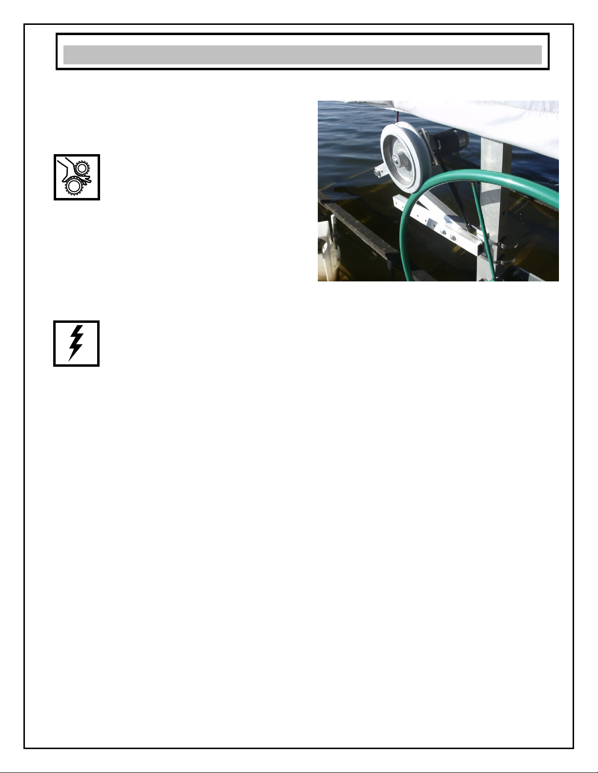
ON/OFF SWITCH
The Lift Mate has a rocker style on/off switch.
1. Hold the switch up to raise the lift.
2. Hold the switch down to lower the lift.
Caution: Stay clear of all moving
parts during raising and lowering of
the lift. There are exposed moving
parts that can pinch fingers, causing
serious injury.
If the motor wheel chatters or slips during operation,
it is just a matter of adding more tension. Adjust the
existing rubber strap to increase tension or add
additional straps.
During a rain or when the wheels are wet from dew
or spray, you will most likely experience slippage.
The operator may need to assist the big lift wheel by
turning on the lift’s crank knob.
Caution: It is recommended to
disconnect the power to Lift Mate
when not in use.
MAINTENANCE
The Lift Mate is basically maintenance free with the
exception of periodic inspections. It is recommended
to periodically inspect the complete unit. Refer to the
following Inspection List:
Caution: It is recommended to disconnect the
power to Lift Mate when performing maintenance
procedures.
1. Tighten all hardware.
2. Inspect rubber traction wheel for proper
alignment. Align if required.
3. Inspect motor brushes and replace as needed.
Caution: It is recommended to disconnect the
power to Lift Mate when performing maintenance
procedures
4. Inspect rubber poly strap for proper tension.
Repair or replace as needed.
5. Inspect electrical connections for worn or frayed
connections. Repair or replace as needed.
OFF SEASON STORAGE
It is recommended to remove the motor from the
outer arm and store in a dry place during the off
season.
FIG. 20
10
OPERATING, MAINTENANCE AND STORAGE INSTRUCTIONS
Left Winch Post Installation
Left Winch Post Installation
Right Winch Post Installation
Right Winch Post Installation
11
Winch Post
Pivot
Bolt
Outer Arm
Winch Post
Outer Arm
Winch Post
Rubber Strap
Rubber Strap
Outer
Arm
Strap Strap
Outer
Arm
Winch
Post
Rectangular Lift With Canopy
Rectangular Lift Without Canopy
Left Winch Post Installation
Left Winch Post Installation
Right Winch Post Installation
Right Winch Post Installation
12
Outer
Arm
Inner
Arm
Winch
Post
Bolt
Band
Straps
Outer
Arm
Inner
Arm
Winch
Post
Bolt
Band
Straps
Canopy Post
Band
Straps
Bolt
Heads
Inner Arm Outer Arm
Outer
Arm
Outer
Arm
Outer Arm Inner Arm Canopy Post
Band
Straps
Bolt
Heads
OR
Pivot
Hole
OR
Pivot
Hole
ShoreMaster Aluminum Platform Hoists
Aluminum Shore Station
Pivot
Hole
Pivot
Hole

Left Winch Post Installation
Right Winch Post Installation
13
Band
Straps
Inner
Arm Pivot
Hole
Outer
Arm
Pivot
Hole
Inner
Arm
Outer
Arm
Band
Straps
Steel Shore Station

Problem
Cause
Remedy
Motor will not run
1. Not connected to power source.
2. GFI button tripped.
3. Wiring and connections
corroded, worn, or frayed.
4. Motor brushes worn, corroded,
or need replacing.
1. Connect to power source.
2. Push in reset button on GFI.
3. Repair or Replace.
4. Repair or Replace.
12 volt Motor rotating
in the wrong direction
1. Cable leads at battery are
reversed.
1. Reverse cable leads at battery.
110 volt Motor rotating
in the wrong
direction
1. Call retailer. 1. Call retailer.
Rubber traction wheel
slipping on lift wheel
1. Wet lift wheel.
2. Rubber poly strap not tensioned
properly.
3. Incorrectly installed.
1. Dry off lift wheel.
2. Create more tension by stretching
rubber poly strap to a new
mounting
position.
3. Review installation procedures.
The groove on the
rubber traction wheel
will not stay in place
against the lift wheel
1. Rubber traction wheel not
aligned properly.
2. 5/8” pivot bolt nut over
tightened.
1. Review installation procedures.
2. Do not over tighten nut. Install and
tighten per installation instructions.
Remote does not work
Remote may be locked. Too lock and unlock your remote, press
two small blue buttons on the sides at
the same time. You will hear a tone
when affective.
Remote does not work
Batteries may be dead
Replace Batteries.
Remote does not work
Remote not synced with control
unit.
14
Exploded View
15
5
6
2
8
4
13
3
14
11
9, 10
15
16, 17
( Not Shown)
23

Parts List
Part
Number
Description Qty
1. 1014519 12” Rubber Poly Strap (Not Shown) 1
2. 1002614 Nut 5/8 - 11 SS Pivot Nut 1
3. 1002458 Bolt 5/8 - 11 X 4 SS Pivot Bolt 1
4. 1014432 Bolt 5/16 X 3" Zinc L/M Kit 2
5.
1014429
Nut 5/16 Zinc Steel (L/M Kit) 2
6. 1002608 5/16” Washers SS 4
7. NA 0
8. 1014564 5” Metal Band Straps 2
9.
1014328
12 Volt Motor Assy. 1
10. 1014247 110 Volt Motor 1
11. 1014376 15 Foot Battery Cable (12 Volt Only) 1
12. 1014387/1014467 18” Outlet Cord and 6” GFI Cord (Not
Shown) 1
13. 1014481 Inner Arm 1
14. 1014490 Outer Arm 1
15.
1014479
Rubber Traction Wheel & Wheel Key 1
16. 1014327 12 Volt Motor Brushes (Not Shown) 1
17. 1014276 110 Volt Motor Brushes (Not Shown) 1
Optional Equipment
18. 1015017-1012023 Motor Cover (Not Shown) 1
19.
1014224/1014318
Remote Control (Not Shown) (110V
or 12V)
1
20. 1014389
20 Ft Battery Cable (Not Shown) 1
21. 1014392
25 Ft Battery Cable (Not Shown) 1
22. 1014399
30 Ft Battery Cable (Not Shown) 1
23.
1014796
Pontoon Kit 1
24. 1014775 Overdock Kit (not shown) 1
16
Table of contents
Popular Lifting System manuals by other brands

Manutan
Manutan A170349 instructions

morse
morse 400A-60-120 Operator's manual

Blitz
Blitz GWSK operating instructions

Central Hydraulics
Central Hydraulics 1647 Assembly and operating instructions

Lippert Components
Lippert Components Power Gear owner's manual

Presto
Presto TT Series Installation, operation and service manual


