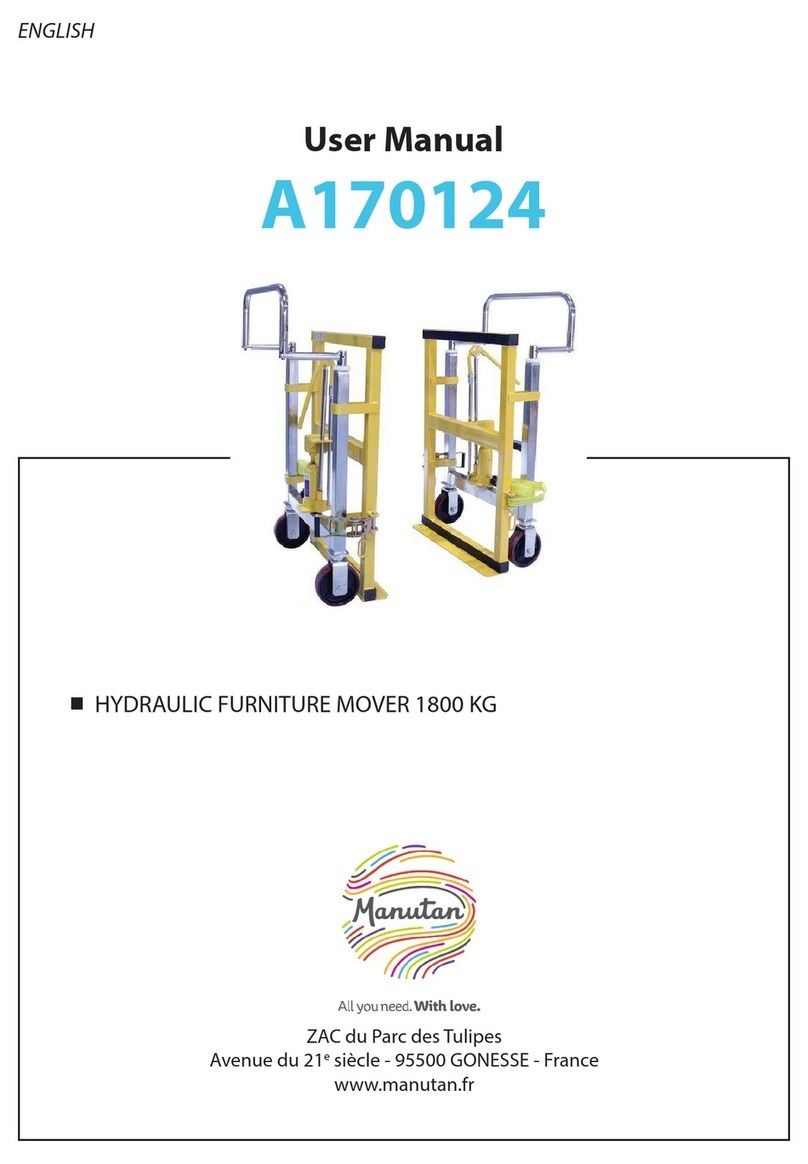
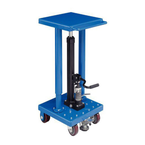
Manutan A170349 User manual

ENGLISH
Hydraulic Lift Table
Instructions
A170349
ZAC du Parc des Tulipes
Avenue du 21esiècle - 95500 GONESSE - France
www.manutan.fr

TABLE OF CONTENTS
1. Main technical parameters
2. Scope of application
3. Conditions for operation
4. Warning
5. Operation methods
6. Maintenance and upkeep
7. Assembly method
8. Parts labels
9. Spare parts catalogue

Main technical parameters
A170349
Capacity kg 1000
Max. lift height mm 1000
Min. table height mm 415
Table size mm 1016 x 510
Handle height mm 990
Wheel diameter mm 150
Service weight kg 114

Scope of application
e table li truck is a type of high-li transportation tool which can be used for short-distance
transportation as well as for liing and lowering goods. In addition, it can be used to store equip-
ment in a workshop.
Conditions for operation
1. e li table should be operated on solid, at ground.
2. Operation temperature: -20–+40C°.
Warning
1. Please read the instructions carefully before operation and familiarise yourself with the per-
formance and operation requirements of the li table. e hydraulic li table may not be used
unless the user has received prior authorisation.
2. Do not overload the hydraulic li table. Please operate it within the rated load. Overloading
will cause damage to both the hydraulic li table and the human body.
3. Operators are forbidden to stand or sit on the table while working.
4. Do not place hands or feet underneath the lowering table.
5. Please apply the brake when loading goods to prevent the truck from moving.
6. Goods must not be loaded in an unbalanced manner. Goods should be distributed evenly
across the whole table.
7. It is not permitted to load loose or unstable goods.
8. Do not leave goods on the work table for a long period of time.
9. e truck cannot be moved while goods are being lied.
10. e truck can only be moved on at, hard ground. Do not use the truck on sloping or uneven
ground.
11. When placing goods on the raised table, the weight of goods should be within the rated load
and the goods should be loaded carefully. (e safety valve only works during the liing pro-
cess. If the truck is raised and overweight goods are placed on it, the safety valve will not work.
is may cause damage to the truck.)
12. When loading and unloading goods on the raised table, do not drag goods in a crosswise
direction. is may cause the load to become severely unbalanced and cause the truck to
overturn.
13. When maintaining and repairing the truck, the stand bar should be used to support the fork
arm in order to prevent the table from falling (there should be no goods on table). is also
ensures safety during maintenance and repair work.
14. Please operate in strict accordance with the "Warning" section, otherwise there is a risk of
damage to the truck and the human body.

Operation methods
1. Press the foot lever several times to raise the work table.
2. Raise the handle lever slowly and open the one-way valve to ensure that the work table des-
cends slowly.
3. Release the brake before moving the truck.
Maintenance and upkeep
It is very important to carry out the necessary maintenance and upkeep tasks to prolong the ser-
vice life and safety of the li table. Please check the li table before operation in accordance with
the following list:
1. Check whether the li table bends or distorts in various positions.
2. Check the truck brake and the condition and amount of wear on the wheels.
3. Check whether there is any oil leakage in the hydraulic system.
4. Before operation each day, add or top up the lubricant to each surface subject to friction.
5. In the event of a failure, the li table should be repaired straight away, before being put back
into operation.
6. Change the hydraulic oil every twelve months. Choose the following hydraulic oil, or a similar
brand, depending on the climate conditions in dierent areas:
• YBN32 retains its properties at an ambient temperature of between -10°C and +40°C.
• YCN32 retains its properties at an ambient temperature of between -20°C and +40°C.

Assembly method
e handle and foot lever are dismantled when the truck leaves the factory. e user can reas-
semble them before operation. e assembly method is as follows:
• Handle installation method (as shown in the following diagram): Fix the handle (B1) to
the mounting hole of the truck body (A) using the bolt (B7), spring washer (B6) and at
washer (B5). en tighten the bolt (B7) using a wrench.
• Foot lever mounting: Insert the foot lever (B31) into the hole. en insert the screw (B29),
the plain washer (B27) and the spring washer (B28). Tighten the screw (B29) using a
wrench.

Parts labels
1 Handle lever
2Handle
3 Foot lever
4Table
5Scissor
6Frame
7 Pump

Spare parts catalogue

No. Name Qty. B25 Pin 1
B1 Handle 1 B26 Spacer bush 1
B2 Handle lever 1 B27 Washer 1
B3 Brake line 1 B28 Spring washer 1
B4 Spring pin 1 B29 Screw 1
B5 Washer 2 B30 Rubber tube 1
B6 Spring Washer 2 B31 Foot lever 1
B7 Screw 2 B32 Connecting rod 1
B8 Screw 2 B33 Table 1
B9 Nut 2 B34 Scissor 1
B10 Axle retaining ring 1 B35 Axle retaining ring 4
B11 Bush 2 B36 Sha 4
B12 Axle 1 B37 Pulley 4
B13 Pump 1 B38 Frame 1
B14 Clamp screw 1 B39 Screw 8
B15 Washer 1 B40 Washer 16
B16 Nut 1 B41 Universal wheel 2
B17 Axle retaining ring 2 B42 Nut 8
B18 Sha 1 B43 Nut 4
B19 Long spacer bush 1 B44 Base for universal wheel 2
B20 Short spacer bush 1 B45 Dust cover 4
B21 Cotter 2 B46 Wheel 4
B22 Pin 1 B47 Brake pad 2
B23 Link 2 B48 Brake lever 2
B24 Washer 2 B49 Screw 4

Pump spare parts catalogue

No. Name Qty. B123 Sealing screw 1
B101 Pump core 1 B124 O-ring 1
B102 Spring cover 1 B125 Base for steel ball 1
B103 Spring 1 B126 Axle retaining ring 1
B104 Dust ring 1 B127 Lever plate 1
B105 Sealing ring 1 B128 Pin 1
B106 Pump cylinder 1 B129 O-ring 2
B107 O-Ring 1 B130 Strike pin 1
B108 Pump base 1 B131 Sealing ring 1
B109 Steel ball 1 B132 O-ring 1
B110 Spring 1 B133 Nylon washer 1
B111 Pressure adjustment
screw 1 B134 Cylinder 1
B112 O-Ring 1 B135 Axle retaining ring 1
B113 Base for steel ball 1 B136 Piston 1
B114 Screw 1 B137 Piston rod 1
B115 Steel ball 1 B138 O-ring 1
B116 Spring 1 B139 O-ring 1
B117 Steel ball 1 B140 Sealing screw 1
B118 Steel ball 1 B141 Dust ring 1
B119 Steel ball 1 B142 Housing 1
B120 Spring 1 B143 Nylon washer 1
B121 Valve 1 B144 Cylinder cap 1
B122 Gasket compound 1 B145 O-ring 1

NEDERLANDS
Hydraulische heftafel
Instructies
A170349
ZAC du Parc des Tulipes
Avenue du 21esiècle - 95500 Gonesse - Frankrijk
www.manutan.nl

INHOUD
1. Belangrijkste technische parameters
2. Toepassingsgebied
3. Voorwaarden voor bediening
4. Waarschuwing
5. Bedieningsmethodes
6. Onderhoud en service
7. Montagemethode
8. Onderdelenetiketten
9. Catalogus met reserveonderdelen

Belangrijkste technische parameters
A170349
Capaciteit kg 1000
Max. hefhoogte mm 1000
Min. tafelhoogte mm 415
Tabelformaat mm 1016 x 510
Hoogte van handgreep mm 990
Wieldiameter mm 150
Bedrijfsgewicht kg 114

Toepassingsgebied
De heafeltruck is een type transportmaterieel voor hoog heen dat kan worden gebruikt voor
korte-afstandstransport en het voor heen en neerlaten van goederen. Daarnaast kan hij worden
gebruikt voor het opslaan van materieel in een werkplaats.
Voorwaarden voor bediening
1. De heafel mag alleen worden gebruikt op een stevige, vlakke ondergrond.
2. Bedrijfstemperatuur: -20 tot +40 °C.
Waarschuwing
1. Lees vóór gebruik de instructies aandachtig door en maak uzelf vertrouwd met de prestaties
en bedieningsvereisten van de heafel. De hydraulische heafel mag niet worden gebruikt
zonder voorafgaande toestemming.
2. Voorkom overbelasting van de hydraulische heafel. Gebruik hem alleen binnen de nominale
belasting. Overbelasting leidt zowel tot schade aan de hydraulische heafel als tot persoonlijk
letsel.
3. Operators mogen niet op tafel staan of zitten tijdens de werkzaamheden.
4. Plaats geen handen of voeten onder de tafel wanneer deze omlaag beweegt.
5. Zorg dat de wielen op de rem staan tijdens het laden van goederen, om te voorkomen dat de
truck kan bewegen.
6. Goederen moeten op gebalanceerde wijze worden geladen. Goederen moeten gelijkmatig
worden verdeeld over de hele tafel.
7. Het is niet toegestaan om losse of onstabiele goederen te laden.
8. Laat goederen niet langdurig op de werktafel liggen.
9. De truck mag niet worden verplaatst terwijl goederen worden geheven.
10. De truck mag alleen worden verplaatst over een vlakke, harde ondergrond. Gebruik de truck
niet op hellende of ongelijke ondergronden.
11. Wanneer goederen op de geheven tafel worden geplaatst, moet het gewicht van de goederen
binnen de nominale belastingswaarde vallen en moeten de goederen voorzichtig worden
geladen. (De veiligheidsklep werkt alleen tijdens het heen. Als de tafel van de truck is geheven
en er te zware goederen op worden geplaatst, werkt de veiligheidsklep niet. Dit kan leiden tot
schade aan de truck.)
12. Bij het laden en lossen van goederen op/van de geheven tafel, mogen de goederen niet in
dwarsrichting worden gesleept. Dit kan ertoe leiden dat de belasting ernstig uit balans raakt,
waardoor de truck kan omvallen.
13. Bij het uitvoeren van onderhoud en reparaties aan de truck, moet de standstang moeten
worden gebruikt ter ondersteuning van de vorkarm, om te voorkomen dat de tafel valt (er
mogen zich geen goederen op de tafel bevinden). Dit zorgt ook voor veiligheid tijdens het
onderhouds- en reparatiewerkzaamheden.
14. Houd u bij de werkzaamheden strikt aan het gedeelte "Waarschuwingen", anders bestaat het
risico van schade aan de truck en persoonlijk letsel.

Bedieningsmethodes
1. Trap diverse keren op de voethendel om de werktafel te heen.
2. Breng de hendel op de handgreep langzaam omhoog en open de terugslagklep om ervoor te
zorgen dat de werktafel langzaam omlaag komt.
3. Zet de rem vrij voordat u de truck verplaatst.
Onderhoud en service
Het is zeer belangrijk dat de vereiste onderhouds- en servicewerkzaamheden worden uitgevoerd,
om de levensduur van de heafel te verlengen en de veiligheid te garanderen. Controleer de
heafel vóór gebruik aan de hand van de volgende lijst:
1. Controleer of de heafel buigt of vervormt in verschillende standen.
2. Controleer de rem van de truck en de staat en mate van slijtage van de wielen.
3. Controleer of er geen sprake is van olielekkage in het hydraulisch systeem.
4. Breng elke dag vóór gebruik smeermiddel aan op elk oppervlak dat wrijving ondervindt.
5. In het geval van een defect moet de heafel onmiddellijk worden gerepareerd alvorens weer
in bedrijf te worden genomen.
6. Ververs de hydraulische olie om de twaalf maanden. Gebruik de volgende hydraulische olie of
een vergelijkbaar merk, aankelijk van het klimaat in verschillende gebieden:
• YBN32 behoudt zijn eigenschappen bij omgevingstemperaturen tussen -10°C en +40°C.
• YCN32 behoudt zijn eigenschappen bij omgevingstemperaturen tussen -20°C en +40°C.

Montagemethode
De handgreep en voethendel worden gedemonteerd wanneer de truck de fabriek verlaat.
Degebruiker kan ze weer monteren vóór gebruik. De montagemethode is als volgt:
• Methode voor het aanbrengen van de handgreep (zoals weergegeven in het volgende
schema): bevestig de handgreep (B1) op het bevestigingsgat in het frame van de truck (A)
met behulp van de bout (B7), de veerring (B6) en de platte sluitring (B5). Draai vervolgens
de bout (B7) vast met een moersleutel.
• Montage van de voethendel: plaats de voethendel (B31) in het gat. Plaats vervolgens de
bout (B29), de sluitring (B27) en de veerring (B28). Draai de bout (B29) vast met een
moersleutel.

Onderdelenetiketten
1 Hendel op handgreep
2 Handgreep
3Voethendel
4Tafel
5Schaar
6Frame
7Pomp

Catalogus met reserveonderdelen

Art.nr. Naam Aantal B25 Pin 1
B1 Hendel 1 B26 Afstandsbus 1
B2 Hendel op handgreep 1 B27 Sluitring 1
B3 Remleiding 1 B28 Veerring 1
B4 Veerpen 1 B29 Schroef 1
B5 Sluitring 2 B30 Rubberen buis 1
B6 Veerring 2 B31 Voethendel 1
B7 Schroef 2 B32 Aandrijfstang 1
B8 Schroef 2 B33 Tafel 1
B9 Moer 2 B34 Schaar 1
B10 Asborgring 1 B35 Asborgring 4
B11 Bus 2 B36 As 4
B12 As 1 B37 Poelie 4
B13 Pomp 1 B38 Frame 1
B14 Klemschroef 1 B39 Schroef 8
B15 Sluitring 1 B40 Sluitring 16
B16 Moer 1 B41 Universeel wiel 2
B17 Asborgring 2 B42 Moer 8
B18 As 1 B43 Moer 4
B19 Lange afstandsbus 1 B44 Basis voor universeel
wiel 2
B20 Korte afstandsbus 1 B45 Stoap 4
B21 Splitpen 2 B46 Wiel 4
B22 Pin 1 B47 Remblok 2
B23 Koppeling 2 B48 Remhendel 2
B24 Sluitring 2 B49 Schroef 4
Table of contents
Other Manutan Lifting System manuals
Popular Lifting System manuals by other brands

VMB
VMB TL-A150 instructions

EZ Carrier
EZ Carrier EZCLA user manual

STS
STS DTP05 Operation and maintenance manual

WITTUR
WITTUR DMG Liftmaterial installation manual

Omer
Omer VEGA 240/50 Instructions & user's manual

HOMECARE PRODUCTS
HOMECARE PRODUCTS EZ-ACCESS TILT Toilet Incline Lift Corded... Installation and user manual