Shoremaster TowerMax User manual
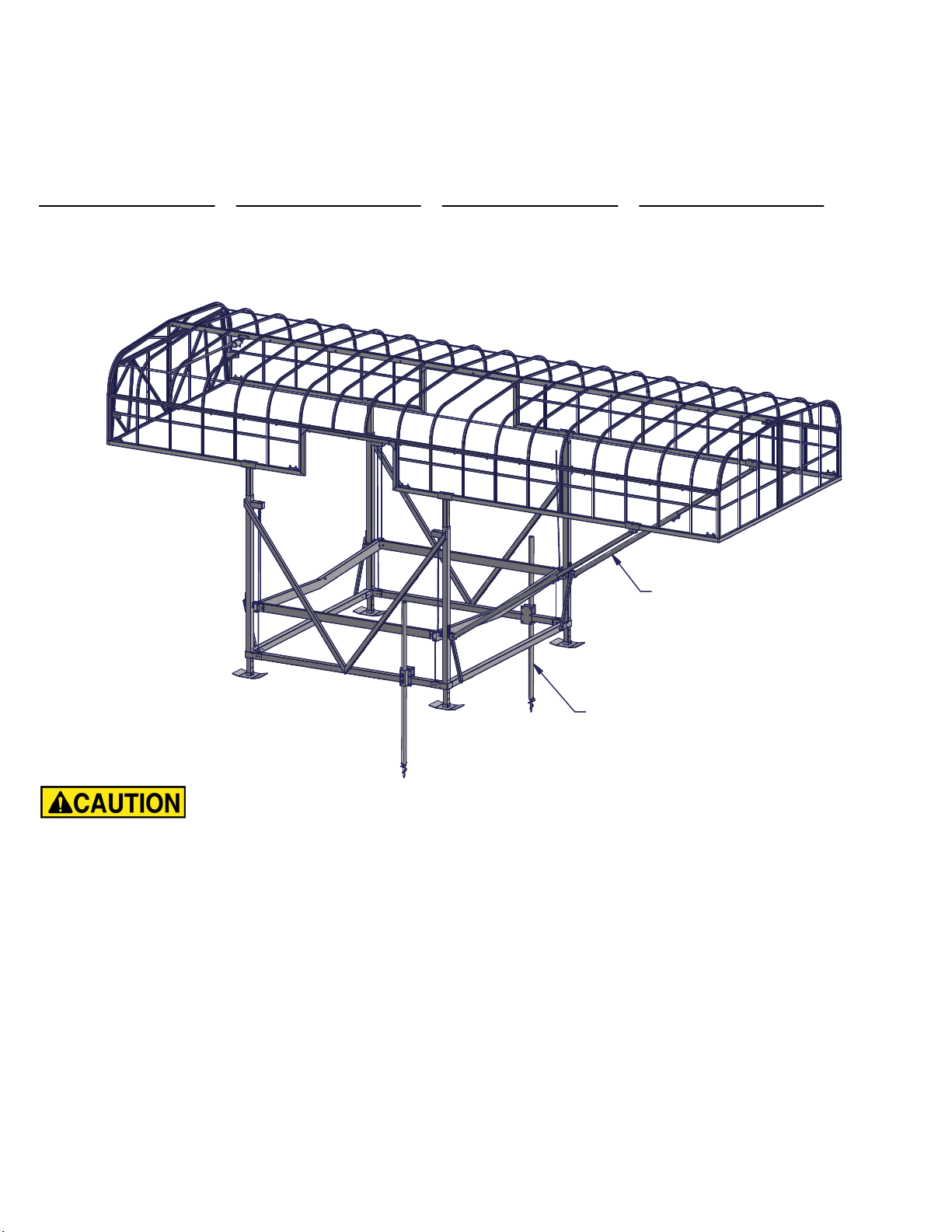
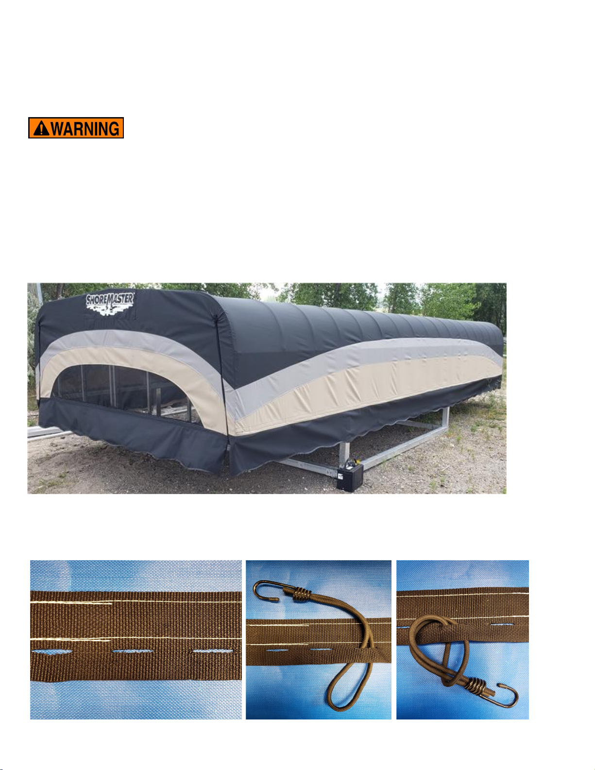
TowerMax Canopy
Instructions
Part #:
10ft Wide 12 Volt System 10ft Wide 120 Volt System 11ft Wide 12 Volt System 11ft Wide 120 Volt System
1042234 - 25x120 1042245 - 25x120 1042239 - 25x132 1042250 - 25x132
1042235 - 27x120 1042246 - 27x120 1042240 - 27x132 1042251 - 27x132
1042236 - 29x120 1042247 - 29x120 1042241 - 29x132 1042252 - 29x132
1042237 - 31x120 1042248 - 31x120 1042242 - 31x132 1042253 - 31x132
1042238 - 33x120 1042249 - 33x120 1042243 - 33x132 1042254 - 33x132
1042244 - 35x132 1042255 - 35x132
- PUT SAFETY FIRST
Failure to follow instructions may result in personal injury and may invalidate the applicable
warranty.
-Before attempting to install this canopy, study and fully understand the proper operating procedures
and safety precautions outlined in this owner's manual.
-To avoid personal injury use proper protective clothing and safety eyewear when assembling,
installing, removing, or servicing this product.
-A canopy frame with the canopy cover attached is a wind hazard! Do not leave cover on frame unless
canopy is secured to a properly installed boat lift.
-Canopy frame andcover cannot support excess weight. Do not stand on, hang from, or set heavy
objects on canopy.
-Inspect all canopy bolts, nuts, cords, and hooks every three months for loose or damaged parts.
Tighten or replace parts as needed.
-If you have any questions about assembly, installation, or suitability of this product, contact an
authorized dealer or ShoreMaster directly.
Canopy Braces included for
canopy lengths 27ft and longer.
Lift Anchor Kit (PN: 1045871)
recommended for areas with high wind.
(Sold Separately)
- Your safety is the most important issue related to this product. It is
critical that all assemblers, installers, and users read and fully understand the warnings and
safety information contained throughout this manual before using this product. Failure to
follow instructions may result in personal injury and may invalidate the applicable warranty.
Installation
A TowerMax canopy may fit more than one boat lift model. A TowerMax canopy may fit many
non-ShoreMaster brands. Contact ShoreMaster or an authorized dealer for more information.
Note: Canopy warranty applies only if installed with a genuine ShoreMaster manufactured frame and cover.
The information in this manual is not all inclusive and does not cover all unique situations. Questions about
assembly, installation, use, or suitability of this product can be answered by contacting an authorized
ShoreMaster dealer.
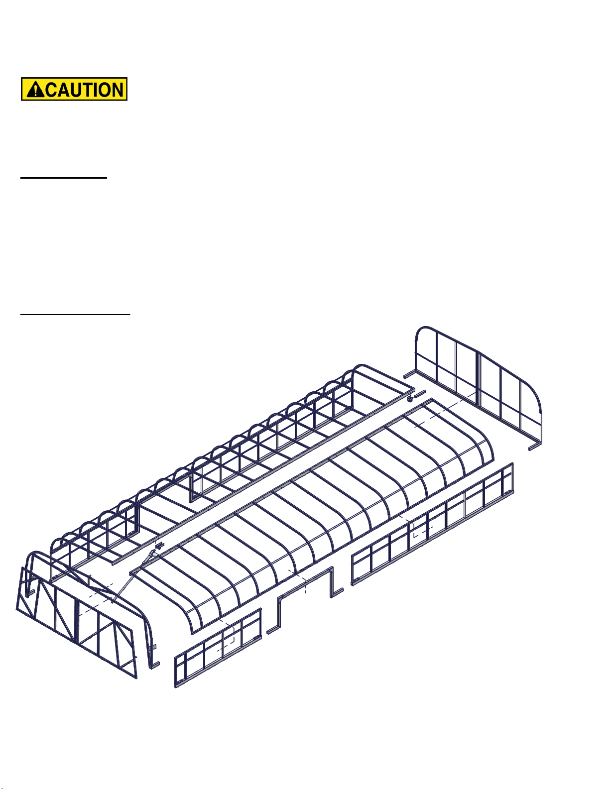
Canopy Parts
-Two full length frame sides (Top)
-Two short length sides (Bottom)
-Two longer length sides (Bottom)
-Two side access door frames
-One full end
-Door End
-Door Weldment
-One actuator kit and hardware

DETAIL A
SCALE 1 / 3
Parts List
DESCRIPTION
ITEM
Wdmt TowerMax Side
1
Washer Flat 3/8 SS
2
Bolt Hex 3/8-16 x 2.75 SS 304
3
Nut Flange 3/8-16 Brass
4
A
Assembly and Installation
4.0
6.0
40.0
45.0
4.0
6.0
40.0
45.0
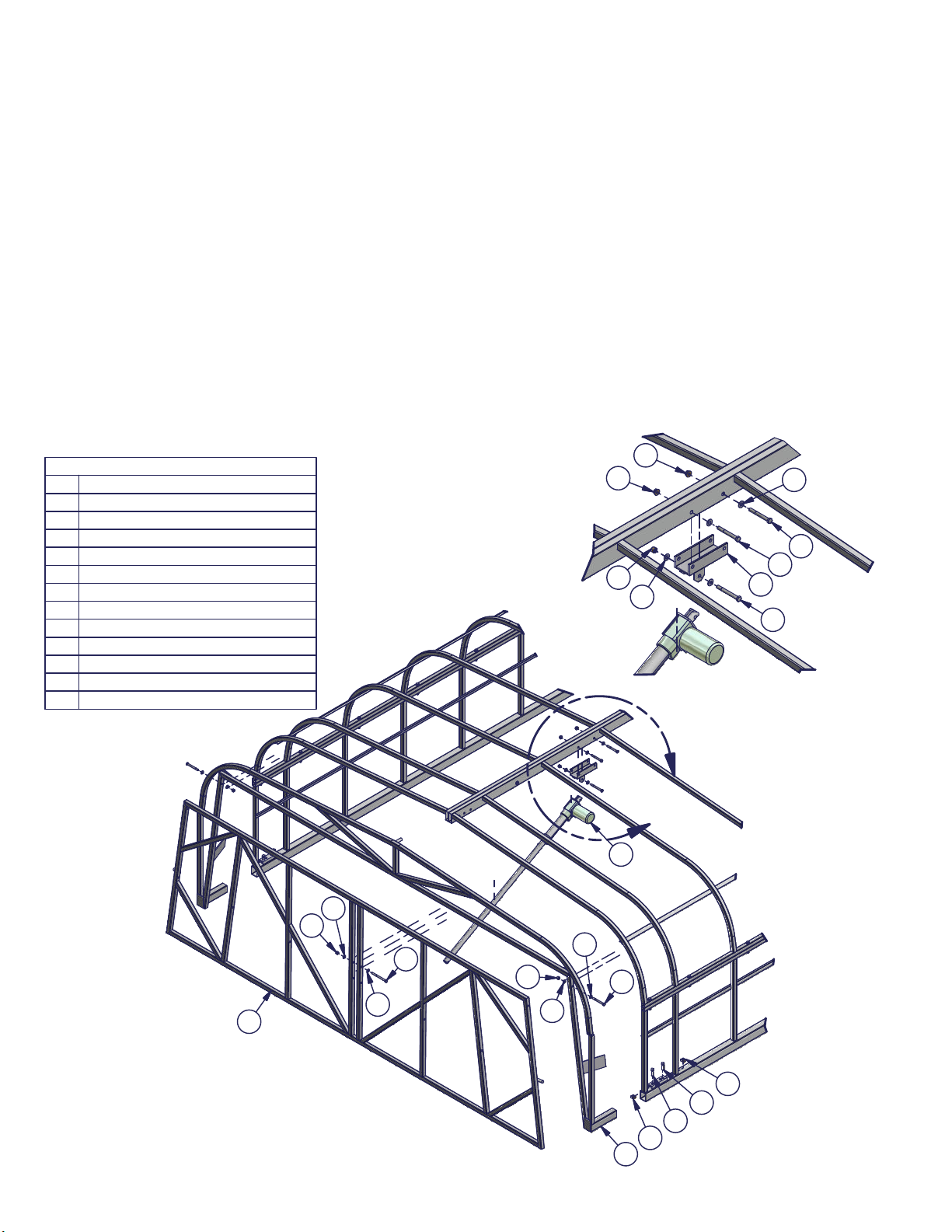
Step 1. Fasten both full length canopy top weldments together using 3/8 x 2.75 bolts, one flat washer
on the bolt head side, and one 3/8 brass flange nut. Every hole along the center rib should get this
hardware, with the exception of the eight holes detailed below. These will be used later for the actuator,
and adjustable end.
NOTE: Measuring from each end, the holes located 4 inches, 6 inches, 40 inches, and 45 inches from
the end should be left open for now.
LEAVE THESE HOLE
LOCATIONS OPEN.
3/8 X 2.75 HEX BOLT
3/8 FLAT WASHER
3/8 BRASS FLANGE NUT

DETAIL B
SCALE 1 / 20
B
Parts List
DESCRIPTION
ITEM
Wdmt TowerMax Top1
Wdmt TowerMax Side Bottom - Longer
2
Wdmt TowerMax Side Bottom - Shorter
3
Wdmt TowerMax Side Door Frame
5
Bolt Hex 3/8-16 x 2.75 SS 304
6
Bolt Hex 3/8-16 x 3.5 SS 304
7
Set Screw 1/2-13 x 1.5 SS 304 Cup Point
8
Nut Flange 3/8-16 Brass
9
Nut Square 1/2-13 Brass
10
Washer Flat 3/8 SS
11
3
2
5
1
1
10
88
10
6
11
7
11
9
Step 2. Assemble the three piece side. Slide the door frame into the bottom tubes of the longer and
shorter side weldments. Make sure the configuration is as desired, with the canopy bungee attachment
angle to the inside of the canopy.
Step 3. Secure the door frame using two 1/2 x 1.5 set screws, and two brass square nuts in each nut
channel.
Step 4. Using 3/8 x 2.75 hex bolts with a flat washer and brass flange nut, bolt the side bottoms to the side
top assembly from Step 1. Bolt the top of the side door frame to the top weldment using 3/8 x 3.5 hex bolts,
flat washers, and flange nuts. Not every hole will require fasteners. The weldments are drilled to
accomodate multiple configurations. Only use hardware near every rib where the holes align all the way
through.
Note: Check configuration to make sure side door is located on desired side, and closer to where the rear
of the boat will be located on the lift, and both sides with the canopy attachment angle to the inside of the
canopy.

DETAIL C
SCALE 1/25
DETAIL D
SCALE 1/7
C
Parts List
DESCRIPTION
ITEM
Wdmt TowerMax Canopy End
1
Wdmt TowerMax End Adjustment Pocket Top2
Prt Tube 1.625 x 1.125 x .125 x 10.03
Bolt Hex 3/8-16 x 4.25 SS 304
4
Bolt Hex 3/8-16 x 3.0 SS 304
5
Set Screw 1/2-13 x 1.5 SS 304 Cup Point
6
Nut Flange 3/8-16 Brass
7
Nut Square 1/2-13 Brass
8
Washer Flat 3/8 SS
9
D
Step 5. Assemble the adjustable end. Place the adjustable pocket onto the center rib of the canopy
top. Bolt in place using two 3/8 x 3.0 hex bolts with flat washers, and two brass flange nuts. Place
square nut into nut channel on the adjustable pocket and lightly thread the set screw just enough to hold
in place. Place the 10 inch tube into the adjustable pocket with the drilled end toward the end of the
canopy. Leave loose for now.
Step 6. Place two square nuts into each nut channel on the ends of the sides and lightly thread a set
screw into each nut, just enough to hold in place.
Step 7. Slide end weldment into the canopy assembly. Bolt 10 inch tube to the end weldment using 3/8
x 4.25 hex bolt, flat washer, and brass flange nut.
1
7
4
9
3
8
8
6
6
7
7
8
2
6
5
5
9
DETAIL E
SCALE 1/25
DETAIL F
SCALE 0.08 : 1
E
Parts List
DESCRIPTION
ITEM
Actuator1
Wdmt TowerMax Canopy Door
2
Wdmt TowerMax Canopy End - Door Side
3
Wdmt TowerMax Actuator Upper Mount4
Bolt Hex 3/8-16 x 4.25 SS 304
5
Bolt Hex 3/8-16 x 3.25 SS 304
6
Bolt Hex 3/8-16 x 3.0 SS 304
7
Set Screw 1/2-13 x 1.5 SS 304 Cup Point
8
Nut Flange 3/8-16 Brass
9
Nut Nyloc 3/8-16 Brass
10
Nut Square 1/2-13 Brass
11
Washer Flat 3/8 SS
12
F
Step 8. Assemble the actuator and door. Place the upper mount onto the center rib of the canopy.
The mounting location for the actuator should be closer to the door end. Secure in place using two
3/8 x 3.0 hex bolts, flat washers, and brass flange nuts.
Step 9. Place the motor end of the actuator into the mounting channel of the upper mount. Secure
actuator in place using a 3/8 x 3.25 hex bolt, flat washer, and brass nylock nut.
Step 10. Slide the Canopy End - Door Side on the the end of the canopy frame. Make sure the top
centering pin slides into one of the center rib tubes for support. Secure in place with the set screws
and brass square nuts on the canopy sides.
Step 11. Mount the door in the frame. Secure in place using a 3/8 x 3.25 hex bolt, two flat washers,
and a brass nylock nut in each top corner of the door frame. Tighten hardware so door is centered
and swings freely. Swing door in to connect rod end of actuator to door using 3/8 x 4.25 bolt, two flat
washers, and one nylock nut.
2
3
10
12
5
12
6
12
12
10
11
8
8
11
1
9
9
7
7
12
4
6
10
12

B
C
D
STEP 6
If you have sliding canopy legs, insert one 3/8 x 1 carriage bolt in the lift leg from the inside and attach
loosely with one 3/8 brass nut as shown.
STEP 7
Slide the slotted canopy leg over the carriage bolt and tighten nut at desired height as shown.
Carriage Bolt
Brass Nut
Lift Winch
Lift Upright
Winch Clamp
Step 12. Remove blue lift caps from boat lift uprights. Lower boat lift rack to full down position and
make sure there is no weight on the lift.
Step 13. Attach four canopy legs by sliding them into exposed opening in lift uprights. Insert one 3/8 x
1 carriage bolt in the lift leg from the inside and attach loosely with one 3/8 brass nut as shown. Slide
the slotted canopy leg over the carriage bolt and tighten nut at desired height as shown.
Each canopy leg must be bolted in place at same level. Keep in mind, the winch upright is longer than
the other three uprights so do not use that as a measuring point.
Note: The level your canopy legs are set at determines how high your canopy is compared with your
boat lift. Canopy should be positioned as low as possible, while still allowing you access to boat from
dock, when your boat is lowered into water. Estimate the distance to fully raise boat out of water (up and
under your canopy) without interference. Proper canopy positioning also requires boat lift to be adjusted
so lift is placed at proper dockside height.
DETAIL G
SCALE 1 / 8
G
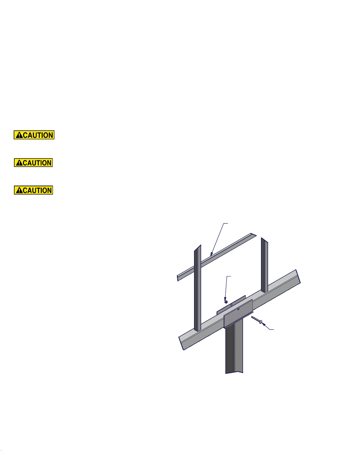
Step 14. Place the assembled canopy frame into the exposed U-shaped channels (saddles) of the
canopy legs. Slide the canopy frame into desired position.
Step 15. Place canopy cover over canopy frame. Position cover so it fits equally over the entire frame.
Note: Frame position should match estimated boat and motor position. Most boats are positioned forward
in lift to provide proper balance and support. The side access door should be near the center of the lift.
Step 16. Bolt the frame in position with four 5/16 carriage bolts, 5/16 nuts, and 5/16 washers. One
attached to each canopy leg as shown. Make sure head of carriage bolt is facing to the outside of the lift
as shown.
To avoid personal injury attach nuts and bolts holding canopy frame to canopy legs very
tight. Not securing this properly could result in frame sliding or falling out of position resulting in damage to
canopy, boat, or lift. A falling or slipping canopy could cause injury to anyone in the area.
Canopy cover is a hazard if exposed to high winds! To avoid personal injury do not attach
cover to canopy frame if wind affects your ability to safely fasten. Do not leave cover unattended on frame
when attaching.
Stretching and attaching bungee cords requires strength and proper balance. To avoid
personal injury always wear proper protective clothing and safety glasses. Do not let go of bungee cords
when under tension. An eye injury or other bodily injury could occur.
Step 17. Be sure the frame is in the desired
position before proceeding.
Step 18. Secure the cover to the frame with
the bungee cords on the inside of the cover.
Take the bungee cord and pull it toward the
outside of the canopy frame, down around the
bottom beam of the canopy frame, and hook
the end to the welded angle strip on the
inside of the canopy bows.
NOTE: Bungees are only needed at every
rib/bow of the cover. On the door end, wrap
bungees around the door opening to the
canopy bows. Some adjustments may be
needed to keep the cover from wrinkling.
Hex Nut
Carriage Bolt
Bungee Attachment Angle

BATTERY
MALE
CONNECTOR
FEMALE
CONNECTOR
REMOTE
BOX
MALE
CONNECTOR
FEMALE
CONNECTOR
MALE
CONNECTOR
FEMALE
CONNECTOR
ACTUATOR
ACTUATOR
FEMALE
CONNECTOR
MALE
CONNECTOR
MALE
CONNECTOR
FEMALE
CONNECTOR
REMOTE
BOX
FEMALE
CONNECTOR
MALE
CONNECTOR
TRANSFORMER
Wiring Information
12V DC System: Connect ring terminals to positive and negative terminals on one battery. The red
wire should go to the (+) terminal. The black wire should go to the (-) terminal. Connect the other side
(male connector) to the female connector of the remote box, this should also have a red and black wire.
Connect the other side of the remote box with a male connector (green and yellow wire) to the female
connector side of the 20ft harness. Connect the other side of the 20ft harness to the wiring harness of
the actuator.
Use the zip ties to tie the wiring to the canopy structure, out of the way.
120V AC System: Connect the male connector side of the transformer to the female side of the
remote box. Connect the other side of the remote box (male connector) to the female connector of the
20ft harness.Connect the other side of the 20ft harness to the wiring harness of the actuator.
Plug the 120V plug on the transformer into the provided GFCI splitter. This can be used to run your
motor as well and should be plugged into your power supply to the lift.
Use the zip ties to tie the wiring to the canopy structure, out of the way.
Consult a qualified electrician for installation or any additional questions.
RED RED GREEN RED BLUE
RED RED GREEN RED BLUE
TowerMax Canopy Cover Attachment
Step 1. Place the cover on the center rib of the canopy frame. Starting at one end and unrolling the
cover down the length of the frame. Make sure the end door is in the proper location for the frame.
Unfold down the side and adjust the cover to fit evenly around the frame.
Step 2. On the inside of the cover, you'll find slits in the webbing to wrap a bungee around. Slip the
bungee into a slit in the webbing and loop the bungee around itself, then pull tight to fasten it to the
canopy cover.
To avoid personal injury, do not let go of bungee cords when under
tension. Stretching and removing bungee cords requires strength and proper balance.
Always wear safety glasses and the proper protective clothing.
A canopy cover is a hazard if exposed to high wind. Do not attach canopy to canopy
frame if wind affects your ability to safely fasten.

Step 3. Starting on the door
side, put one bungee in each
top corner of the door flap
webbing. Pull the bungee
around to the next vertical tube
of the door weldment. Work
your way down to the bottom
corners, placing one bungee
about every 12-18".
Step 4. Place one bungee along
every vertical tube of the door
weldment. Hook the bungee end
into the pre-drilled hole in the
tubes.
Step 5. Starting in the upper corner of
the door, wrap a bungee around to the
inside of the frame. Work your way
down, keeping the same spacing of
12-18". If there are wrinkles in the
cover, pull cover to adjust and work
them out. The webbing should be just
at the bottom of the frame.
Step 6. Place a bungee next to
every upright tube down the sides
and full end of the canopy. Hook the
end of the bungee to the attachment
angle as shown.
Operation and Use
Canopy provides best protection when your boat is positioned up and into the frame.
-Severe or strong winds can pick up a boat, lift, and canopy. This would cause damage to equipment and injury to
anyone in its path. Position your boat up within canopy frame to provide protection and reduce chance of severe
winds circulating inside canopy.
-Do not raise boat lift up past recommended lift height to position boat higher in canopy. Over raising may cause
damage to lift, canopy, or boat. If over raising appears necessary to properly position boat, remove lift and canopy
from water and adjust canopy legs to desired level.
-Do not leave cover on canopy frame unless boat lift is firmly in place. Sink lift leg pads into lake bottom. Settling is
helped by leaving boat on lift for several days and covering lift leg pads with lake bottom soil. These steps provide a
suction effect.
-Secure boat lift with canopy to lake bottom or a stand dock if you have a hard lake bottom (little or no soil),
experience violent winds, or will not have your boat in lift during strong winds. Auger style lift anchor kits are available
separately, part number 1045871.
Removal and Storage
The canopy cover must be removed when boat lift is not properly secure in water or if not being used regularly. You
can remove the cover by detaching the bungee cords from the canopy frame.
-Stretching and removing bungee cords requires strength and proper balance. Do not let go of bungee cords when
under tension. An eye injury or other bodily injury could occur. Always wear proper protective clothing and safety
glasses.
-Canopy frames and covers cannot support extra weight. Remove the cover if you experience snowfall. Not removing
the cover and allowing accumulation of snow on canopy could damage the frame and the cover.
-Store the cover in a warm dry place. Be sure the cover is clean and dry before folding or rolling up for storage.
-Store canopy cover in a warm dry place to avoid cracks from freezing. Do not fold or handle the cover if temperature
is below 45 degrees Fahrenheit, cracking could occur.
Service
A properly maintained canopy will require little service to the frame or structure. A canopy cover used under normal
circumstances should provide 5 - 10 years of use before needing replacement.
Inspect all canopy bolts, nuts, cord, and hooks every three months for loose or damaged parts. Tighten or replace
parts as needed.
Check other parts once a year for cracks, breaks or wear. Replace parts as needed.
If damage occurs to any part, replaced damaged item before resuming use.
Do not use chemicals or abrasives to clean your canopy cover. Using chemicals or abrasives will
destroy your covers sun and mold protection. This will result in premature aging and decay of your cover. Use a soft
dish soap and pressured water to clean your cover.
This manual suits for next models
22
Table of contents
Popular Tent manuals by other brands

P.Lindberg
P.Lindberg 304015 Original manual

OZTENT
OZTENT RV owner's manual

Yardistry
Yardistry YM12831Z installation instructions

Sunjoy
Sunjoy 10'x12' Bay Window Gazebo instruction manual

Outsunny
Outsunny INbvd001V01 GL Assembly & instruction manual

Crua Outdoors
Crua Outdoors Loj TT6 Pitching instructions


Intenda
Intenda Box Tunnel Installation, use and maintenance

Snow Peak
Snow Peak Amenity Dome M instruction manual

Dancover
Dancover Multipavillon 6x6m manual

vidaXL
vidaXL 90338 Operating and safety instructions

Kiwi Camping
Kiwi Camping Tuatara SSE Annex Pitching instructions

Isabella
Isabella Standard 250 CarbonX Erection Instructions