Showline SL BEAM 300 FX User manual
SL BEAM 300 FX
1
Showline Offices
Document Number: SL BEAM 300 FX QuickStart Guide
Version as of: 27th Jan, 2015
SL BEAM 300 FX QuickStart Guide
©2015 Philips Group. All rights reserved.
Dallas
10911 Petal Street
Dallas, TX 75238
Tel: +1 214-647-7880
Fax: +1 214-647-8030
Auckland
19-21 Kawana Street
Northcote, Auckland 0627
New Zealand
Tel: +64 9 481 0100
Fax: +64 9 481 0101
Asia
Unit C, 14/F, Roxy Industrial Centre
No. 41-49 Kwai Cheong Road
Kwai Chung, N.T., Hong Kong
Tel: +852 2796 9786
Fax: +852 2798 6545
Europe
Rondweg zuid 85
Winterswijk 7102 JD
The Netherlands
Tel: +31 (0) 543-542516
www.philips.com/showline
SL BEAM 300 FX QUICKSTART GUIDE
SL BEAM 300 FX QuickStart Guide
SL BEAM 300 FX
2
About Quickstart Guide
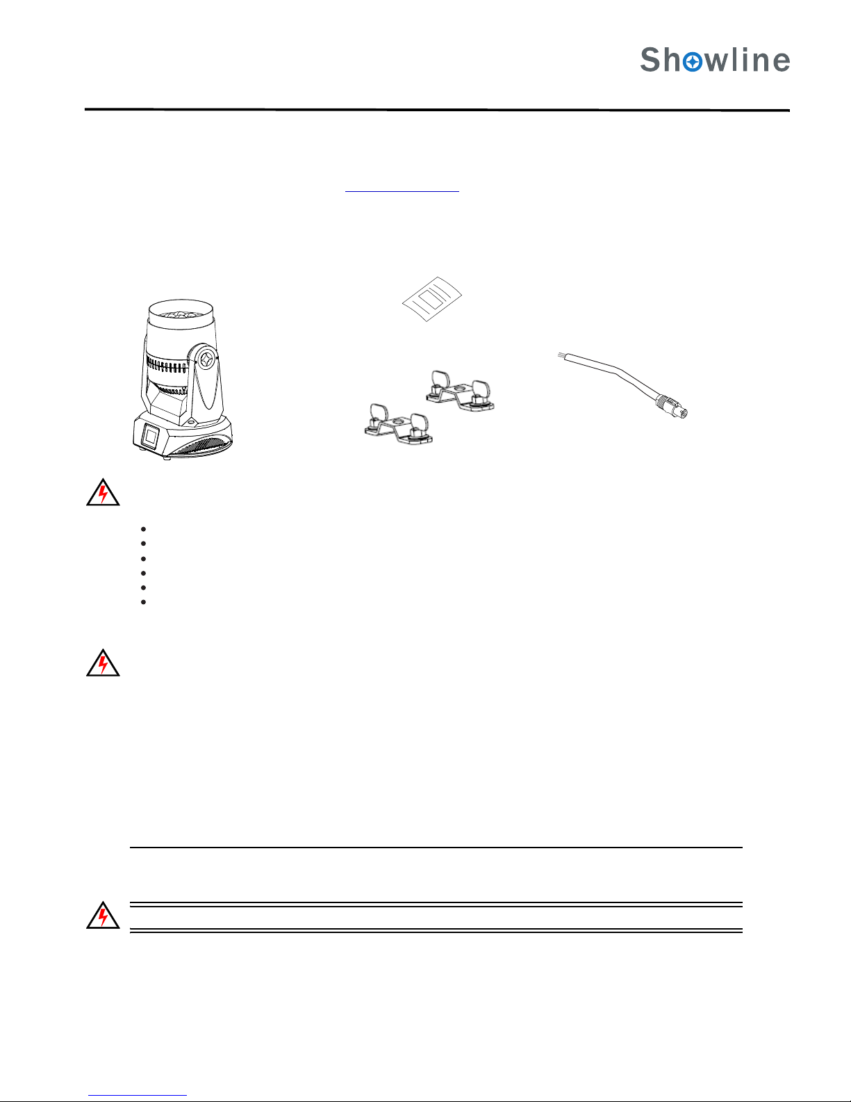
Included Items
Each SL BEAM 300 FX includes the following items:
Figure 1: Included Items
Warnings and Notices
When using electrical equipment, basic safety precautions should always be followed including the following:
READ AND FOLLOW ALL SAFETY INSTRUCTIONS.
D o n o t use outdoors.
D o n o t mount near gas or electric heaters.
E q u i p ment should be mounted in locations and at heights where it will not readily be subjected to tampering by unauthorized personnel.
T h e u se of accessory equipment not recommended by the manufacturer may cause an unsafe condition.
D o n o t use this equipment for other than intended use.
R e f e r service to qualified personnel.
SAVE THIS DOCUMENT FOR FUTURE REFERENCE! READ COMPLETELY BEFORE INSTALLING AND USING PRODUCT!
WARNING: You must have access to a main circuit breaker or other power disconnect device before installing any wiring. Be sure that
power is disconnected by removing fuses or turning the main circuit breaker off before installation. Installing the device with power on may
expose you to dangerous voltages and damage the device. A qualified electrician must perform this installation.
WARNING: Refer to National Electrical Code® and local codes for cable specifications. Failure to use proper cable can result in damage to
equipment or danger to personnel.
WARNING: This equipment is intended for installation in accordance with the National Electric Code® and local regulations. It is also
intended for installation in indoor applications only. Before any electrical work is performed, disconnect power at the circuit breaker or
remove the fuse to avoid shock or damage to the control. It is recommended that a qualified electrician perform this installation.
Service and Maintenance
For all service and maintenance issues, please contact your local Showline office or an Authorized Service Center.
Power Requirements
The SL BEAM 300 FX operates on AC input voltages from 100 to 240 VAC.
SL BEAM 300 FX
QuickStart Guide
AC Input Cable 1.5M
Omega Mounts
(this document)
This Quickstart Guide is intended for a knowledgeable user to unpack, install, and use SL BEAM 300 FX in a short time period. For the complete
manual in PDF format, please visit our web site at : and click the user manual download link on the product page. The www.philips.com/showline
complete manual provides you all information related to accessories, menu structures, DMX channel mapping/modes,and care for your new luminaire.
SL BEAM 300 FX QUICKSTART GUIDE
QuickStart Guide
WARNING: This unit does not contain an ON/OFF switch. Always disconnect power input cable to completely remove power from unit when not in use.

3
Maximum amount of units that may be daisy-chained is (A) 10 units 100VAC (15 Amps) or (B) 20 units 240VAC (15 Amps). Refer to
Table1for detailed information at various voltages.
Note: For wiring of AC input connector, refer to . Connecting SL BEAM 300 FX to AC Power
Ta ble 1: SL BEAM 300 FX Voltage vs. Current
WARNING: *These figures are based on the Maximum Allowable Input Current of 15 Amps. Do not overload circuits!
IMPORTANT AC POWER CONNECTION NOTES:
DO NOT CONNECT OTHER TYPES OF LUMINAIRES OR DEVICES!
Connecting Power
Units can be powered in one of two ways:
D i r e c t connection to a AC power source using an AC input cable. For wiring of AC input connector, refer to Connecting SL BEAM 300 FX
to AC Power.
C o n n e ction from the AC output of another SL BEAM 300 FX. When using this method, it is very important not to
connect any other type of equipment.
Connecting SL BEAM 100 RGBWLED Luminaires to AC Power
Table 2: AC Input Connections
Wire Color
WARNING:
Purpose
WARNING: Only connect other SL BEAM 300 FXs to the AC Output (Thru) connector of a SL BEAM 300 FX.
Table 2, AC Input Connections describes how to connect power to your SL BEAM 300 FX. Field wiring of the SL BEAM 300 FX is
straight forward. A total of 3 wires/conductors is supplied to this unit.
100 1803.50 1.954 7
4 8
5 9
6 9
6 9
6 10
7
5 8
110 1903.18 1.84
160 2402.19 1.46
150 2302.34 1.52
140 2202.50 1.59
130 2102.69 1.67
120 2002.92 1.75
170 2.06
Only use approved cable types.
When using the daisy-chain connection method, only connect SL BEAM 300 FX to AC Output Connection of SL BEAM 300 FX.
Do not overload circuits!
Do not connect SL BEAM 300 FX to dimmed circuits.
Black
White
Green
Main/Line(100 to 240 VAC)
Neutral
Ground(Earth)
SL BEAM 300 FX
SL BEAM 300 FX QUICKSTART GUIDE
QuickStart Guide
AC Power Operation
When connected to an AC source, the unit operates on 100 to 240 volts AC (+/- 10%, auto-ranging). The luminaire contains an auto-ranging power supply.
Each luminaire can draw up to 350 Watts.
Voltage
(AC)
Voltage
(AC)
Total
Current(A)
Total
Current(A)
Maximum
number of units
that can be linked
together*
Maximum
number of units
that can be linked
together*
AC Input and Output Connections
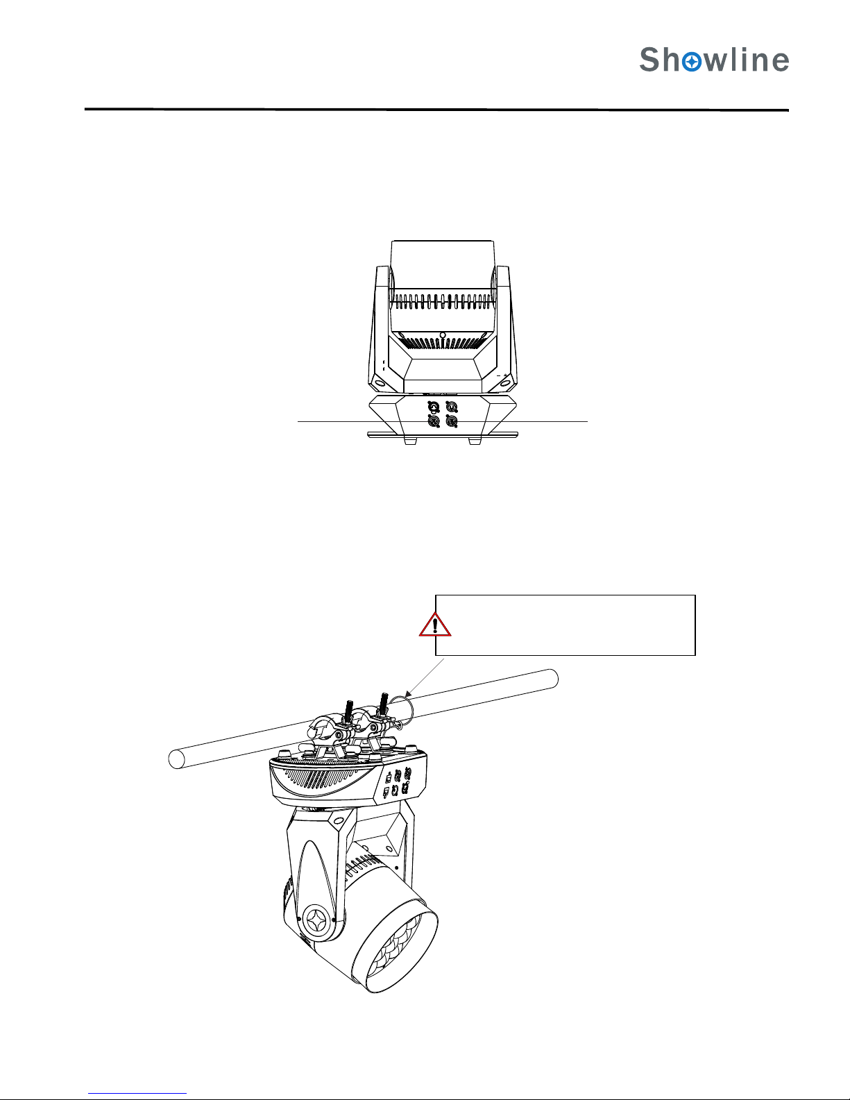
4. Mounting Luminaire
Back of Unit
AC Input AC Output
Truss / Hanging Applications
The SL BEAM 300 FX is provided with the ability to hang via truss hooks, clamps, etc. (sold separately).
Figure 2: AC Input connection
Figure 3: Hanging Application
The SL BEAM 300 FX will be equipped with a 1m power cord with bare end for power input and a white 3pin terminal for power
output. For DMX input and output, 2 DMX plugs are installed.
4SL BEAM 300 FX QUICKSTART GUIDE
SL BEAM 300 FX
QuickStart Guide
SAFETY CABLE: Is sold separately and recommended
for all hanging installation and may be required by
national and local codes. Use enclosure handles for
safety cable anchor points for this fixture.

LCD Display and Menu System
The SL BEAM 300 FX’s LCD Display and Menu System provides local control for accessing the following fixture’s settings:
Presets (Standard and User Defined)
Color Filter
Effects (Chases - preloaded and user defined)
Strobe / Timing
Settings
Lock Fixture (to prevent changes)
Password
Status
Note: If there are multiple luminaires in a system, changes would need to be made at each LCD Menu as desired. For
Upon power up, the LCD will display the main screen showing the product type/name. If DMX is enabled, the
programmed address will appear after power up.
SL BEAM 300 FX
Home (menu settings)
Edit a Preset Edit a Chase
DMX512 Addressing
Return to Main Screen
LEFT Arrow Button UP Arrow Button
OK (Check Mark) Button
DOWN Arrow Button
RIGHT Arrow Button
LCD Display
NOTE: Menu rotates with orientation of Luminaire and
menu buttons are always in the same position (with
rotation of menu)
To rotate menu 180 degrees manually from current
orientation, press and hold the two center buttons for 2
seconds.
Figure 4: Menu System
SL BEAM 300 FX
SL BEAM 300 FX menu structure, please refer to the complete user manual
5 SL BEAM 300 FX QUICKSTART GUIDE
SL BEAM 300 FX QuickStart Guide
EditaPreset
M12%
R0%
G0%
B0%
W0%
OFF AllPixel
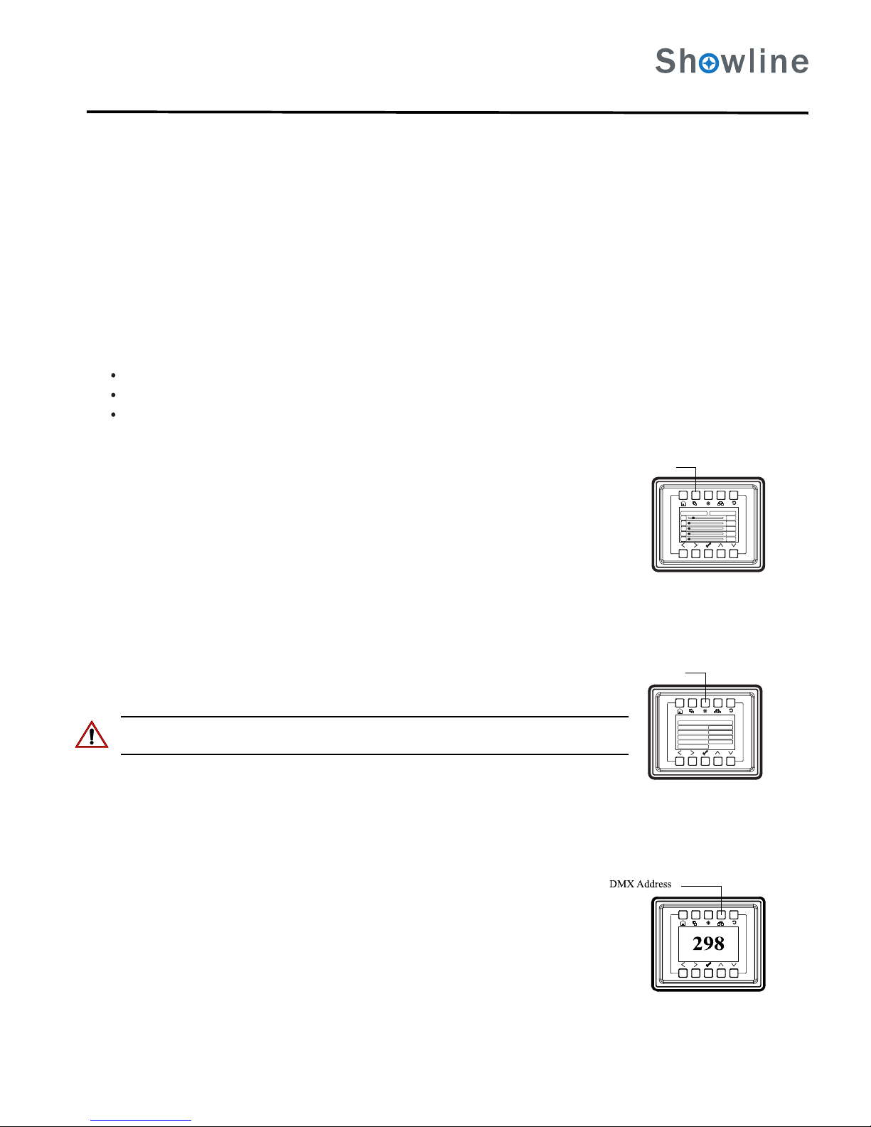
Edit a Preset
To edit and save a DMX address:
EditaChase
UserChase:2
MasterIntensity 39%
TotalSteps 3
EditUserChase
Fade 100%
Speed 1S
Edit a Chase
Address
Step 1. Press Edit a Preset button. Current preset will be shown.
Step 2. Use LEFT and RIGHT arrow buttons to scroll through all presets.
Step 3. Once at desired preset, use UP and DOWN arrows to access (highlight) preset parameters. Once in
desired parameter, use LEFT and RIGHT arrow buttons to adjust parameter value as desired.
Step 4. Once all values are adjusted as desired, press OK (Check Mark) button.
Step 5. Save preset menu option will appear. Use LEFT and RIGHT arrow buttons to select preset number.
Step 6. If saving preset, press OK (Check Mark) button. Confirm choice.
Step 7. Preset is now saved.
Step 3. Once at desired Chase, use UP and DOWN arrows to access (highlight) Chase parameters. Once in
desired parameter, use LEFT and RIGHT arrow buttons to adjust parameter value as desired.
Step 4. Once all values are adjusted as desired, press OK (Check Mark) button.
Step 5. Save Chase menu option will appear. Use LEFT and RIGHT arrow buttons to select Chase number.
Step 6. If saving Chase, press OK (Check Mark) button. Confirm choice.
Step 7. Chase is now saved.
Step 1. Press Edit a Chase button. Current chase will be shown.
Step 2. Use LEFT and RIGHT arrow buttons to scroll through all chases (Built In and User Chases).
Step 1. Press DMX Address button. Current DMX Address will be shown.
Step 2. Press OK (Check Mark) button to highlight a digit in the DMX address.
Step 3. Use LEFT and RIGHT arrow buttons to scroll through all digits.
Step 4. Once at desired dight, use UP and DOWN arrows to change highlighted digit. Once digit is set, use
LEFT and RIGHT arrow buttons to set other digits in DMX address.
Step 5. Once all digits are set in DMX address, press OK (Check Mark) button.
Step 6. DMX will display and is saved.
6
The LCD Display Menu system consists of several categories. Use the Menu Buttons to access and make changes to the menu items. When the
desired menuitems is reached, press the desired Menu Button to display the menu options and to navigate and configure the menu options as required.
LCD Display and Menu System Operation
Quick Selection Buttons
Edit a Preset Button
Edit a Chase Button
DMX Address Button
To navigate and access menu settings/selections:
Step 1. Make sure unit is powered on.
Step 2. Press the desired button ( as shown in ) to access menu categories.Figure 4
Step 3. Use UP/DOWN/LEFT/RIGHT buttons to navigate through the various options and settings.
Step 4. Make changes as desired.
Step 5. Press CHECK MARK (OK) button to accept changes.
When in Manual Mode, the SL BEAM 300 FX features can be accessed via the on-board LCD menu system or via three quick select buttons:
Edit a Preset Button
Edit a Chase Button
DMX Address Button
To edit and save a preset:
To edit and save a Chase:
Note: for Built In Chases, only the Speed and Fade farameters may be changed and saved. For User Chases, Chase
Number, Total Steps, Speed, and Fade Parameters may be changed and saved.
SL BEAM 300 FX QUICKSTART GUIDE
SL BEAM 300 FX
QuickStart Guide

Dallas
10911 Petal Street
Dalls, TX 75238
Tel: +1 214-647-7880
Fax: +1214-647-8031
Asia
Unit C, 14/F, Roxy Industrial Centre
No. 41-49 Kwai Cheong Road
Kwai Chung, N.T., Hong Kong
Tel: +852 2796 9786
Fax: +852 2798 6545
Auckland
19-21 Kawana Street
Northcote, Auckland 0627
New Zealand
Tel: +64 9 481 0100
Fax: +64 9 481 0101
Europe
Rondweg zuid 85
Winterswijk 7012 JD
The Netherlands
Tel: +31 (0) 543-542516
2015 Philips Group
C
Table of contents
Other Showline Floodlight manuals

Popular Floodlight manuals by other brands


Blizzard Lighting
Blizzard Lighting Stiletto Z 19 manual

Tranberg
Tranberg TEF 9964 Helideck user manual

Ustellar
Ustellar UT88873 user guide

Chauvet Professional
Chauvet Professional Rogue Outcast 3 Spot user manual

Robus
Robus RHL1040-04 quick start guide

Eye Lighting
Eye Lighting H573D Installation & maintenance