Showlite DMX Master Pro USB User manual

DMX Master Pro USB
Operators manual
00028353
Version 04-2012

Contents
1 Features........................................................................................................................1
2.General Instructions……………………………………………………………………..……..2
3. Panel description…………………………………………………………………………........3
3.1. Front view instruction……………………………………………………………………..3
3.2.Back Side View………………………………………………………………………...…..6
4. Operation Guide…………………………………………………………………………….….7
4.1 Program Enable……………………………………………………………………...….…7
4.2 Programming Scenes…………………………………………………………………..…7
4.2.1 Scene Editing………………………………………………………………………..9
4.2.2 Scene Copy……………………………………………………………………...…10
4.2.3 Delete a Scene……………………………………………………………..…..….10
4.2.4 Delete all Scenes………………………………………………………………..…11
4.2.5 Bank Copy…………………………………………………………………….....…11
4.2.6 Lamps Copy………………………………………………………………….…….12
4.3 Programming Edit…………………………………………………………………….…..12
4.3.1 Program a bank of scenes into a Program…………………….……………..…12
4.3.2 Add a Step………………………………………………………………….………13
4.3.3 Delete a Step………………………………………………….…………..….……14
4.3.4 Delete a Program………………………………………………………….………14
4.3.5 Delete all the program…………………………………………………...……….…15
4.4 Assign/Reverse DMX channel……………………………………………….……….…15
4.4.1 Assign DMX channel……………………………………………………...………15
4.4.2 Reverse DMX channel…………………………………………………….………16
4.4.3 Pacing model select…………………………………………………………….…17
4.4.4 Delete Assign/Reverse DMX channel……………………………………...……17
4.4.5 Delete all Assign/Reverse DMX channel……………………………..…………17
4.4.6 Check Assign/Reverse DMX channel…………………………………...………18
4.4.7 Set up starting up display information…………………………………...………18
4.5 Running Scenes…………………………………………………………………….……18
4.5.1 Manual Mode………………………………………………………………………18
4.5.2 Auto Mode………………………………………………………………….………19
4.5.3 Music Mode……………………………………………………………...…………19
4.6 Running Chases…………………………………………………………………….……20
4.6.1 Manual Mode………………………………………………………………………20
4.6.2 Auto Mode…………………………………………………………….……………20
4.6.3 Music Mode……………………………………………………...…………………21
4.7 MIDI Operation……………………………………………………………………………21
4.7.1 MIDI Operation………………………………………………….…………………21
4.7.2 Controller MIDI form……………………………………………….………………22
4.8 USB function………………………………………………………………………………22
4.8.1 Data write in USB-Stick by USB……………………………….....………………22

Contents
4.8.2 Reading the USB-Stick data by USB….………………………………..………23
4.8.3 Software promotion by USB………………………………………………..……23
4.9 RMD operration……………………………………………………………………….…24
4.10 Set off Operation………………………………………………………………….……26
1. Features
1. 192 DMX512 channels.DMX512 standard singal output
2. Controlled 12 lights,each light 16 channels.
3. 30 banks of 8 programmable scenes
4. 6 chases of 240 programmed scenes from banks
At most 20 times of every program when opened.
5. Data will be displayed by LCD
6. Voice sensitive can be adjusted
7. 8 channels or 16 channels for each light
8. DMX channel can reversed ,DMX data can change to percent mode
and numerical mode display
9. The scanners under control by Pan and Tilt jog wheels
10. Sliding channel can set up X/Y mode or all channel mode
11. MIDI control over banks, chases and Blackout
12. Machinery can be controlled
13. DMX polarity select
14. Power failure memory
15. Use RDM to Remote control DMX address
16. All the data can be copy by U disk ,also can control the software
promotion by it
17. Support FAT 16/32 file layout

2. General instruction
Please read the user manual carefully, as it includes important information
regarding details of operation, maintenance, and technical data. Keep this manual
with the unit for future consult
WARNINGS
DO NOT make any inflammable liquids, water or metal objects enter the unit.
Should any liquid be spilled on the unit, DISCONNECT the power supply to the unit
immediately.
STOP using the unit immediately In the event of serious operation problems and
either contact your local dealer for a check or contact us directly.
DO NOT open the unit--there are no user serviceable parts inside.
NEVER try to repair the unit yourself. Repairs by unqualified people could cause
damage or faulty operation. Contact your nearest dealer.
CAUTIONS
After having removed the packaging check that the unit is NOT damaged in any
way. If in doubt, DON'T use it and contact an authorized dealer
Packaging material (plastic bags, polystyrene foam, nails, etc.) MUST
NOT be left within children's reach, as it can be dangerous.
This unit must only be operated by adults. DO NOT allow children to tamper or play
with it
NEVER use the unit under the following conditions:
In places subject to excessive humidity.
In places subject to vibrations or bumps.
In places with a temperature of over 45 C/113 F or less than 2 C/35.6 F.
Protect the unit from excessive dryness or humidity (ideal conditions are
between35% and 80%).
DO NOT dismantle or modify the unit.
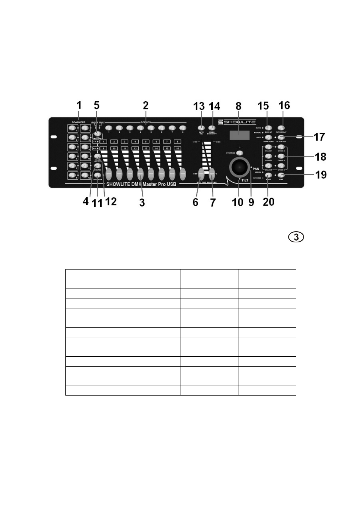
3.Panel description
3.1. Front view instruction
1. Scanner Buttons (1-12)
12 scanners of 16 DMX channels & fader control:
Scanners DMX channels
Fader control LED
1 1-16 On/Off On/Off
2 17-32 On/Off On/Off
3 33-48 On/Off On/Off
4 49-64 On/Off On/Off
5 65-80 On/Off On/Off
6 81-96 On/Off On/Off
7 97-112 On/Off On/Off
8 113-128 On/Off On/Off
9 129-144 On/Off On/Off
10 145-160 On/Off On/Off
11 161-176 On/Off On/Off
12 177-192 On/Off On/Off
Press a scanner button to turn on manual fader control. Press the scanner button
again to turn off fader control. The LED besides the button lights or goes out to
indicate this selection.

2. Scene Buttons
Press the scene buttons to load or stored your scenes.
There are a maximum of 240 programmable scenes.
3. Faders
These faders are used to control the intensity of channel 1-8 or channel
9-16 depending upon the selected page.
4. Page Select Button
Used to select page between Page A(1-8) and Page B(9-16).
5. Fog Machine Button
Activates Fog Machine
6. Speed Slider
Used to adjust the chase speed within the range of 0.1 second to 10 minutes.
7. Fade Time Slider
Used to adjust transition time from one scene to another scene within the range
of 0 seconds to 30 seconds
8. LCD Display
Shows the current activity or programming state.
9. Pan
This jog wheel is used to control the pan of the fine turning
10. Tilt
This jog wheel is used to control the Tilt of the fine turning
11. Program Button
Activates Program mode
12. MIDI/Rec
Used to control MIDI operation or to record programs
13. Auto/Del
Activates Auto mode or to delete scenes or chases
14. Music/Bank Copy
Activates Music mode or to copy a bank of scenes
15. Bank Up/Down
Press the Up/Down button to select from 30 banks
16. Tap/Display
Used to create a standard beat or to change the value mode between 0-255.
17. Blackout
Tap to momentarily pause whole output.hold on this button enter Stand alone
18.Chase Buttons(1-6)
These buttons are used for activating the chase of programmed scenes.
19. Fine Button
When Fine is on, the Pan or Tilt wheel will control the scanner more exactly
20. Mode Button
Pressing Fine and Mode buttons allows to activate Assign or Reverse mode
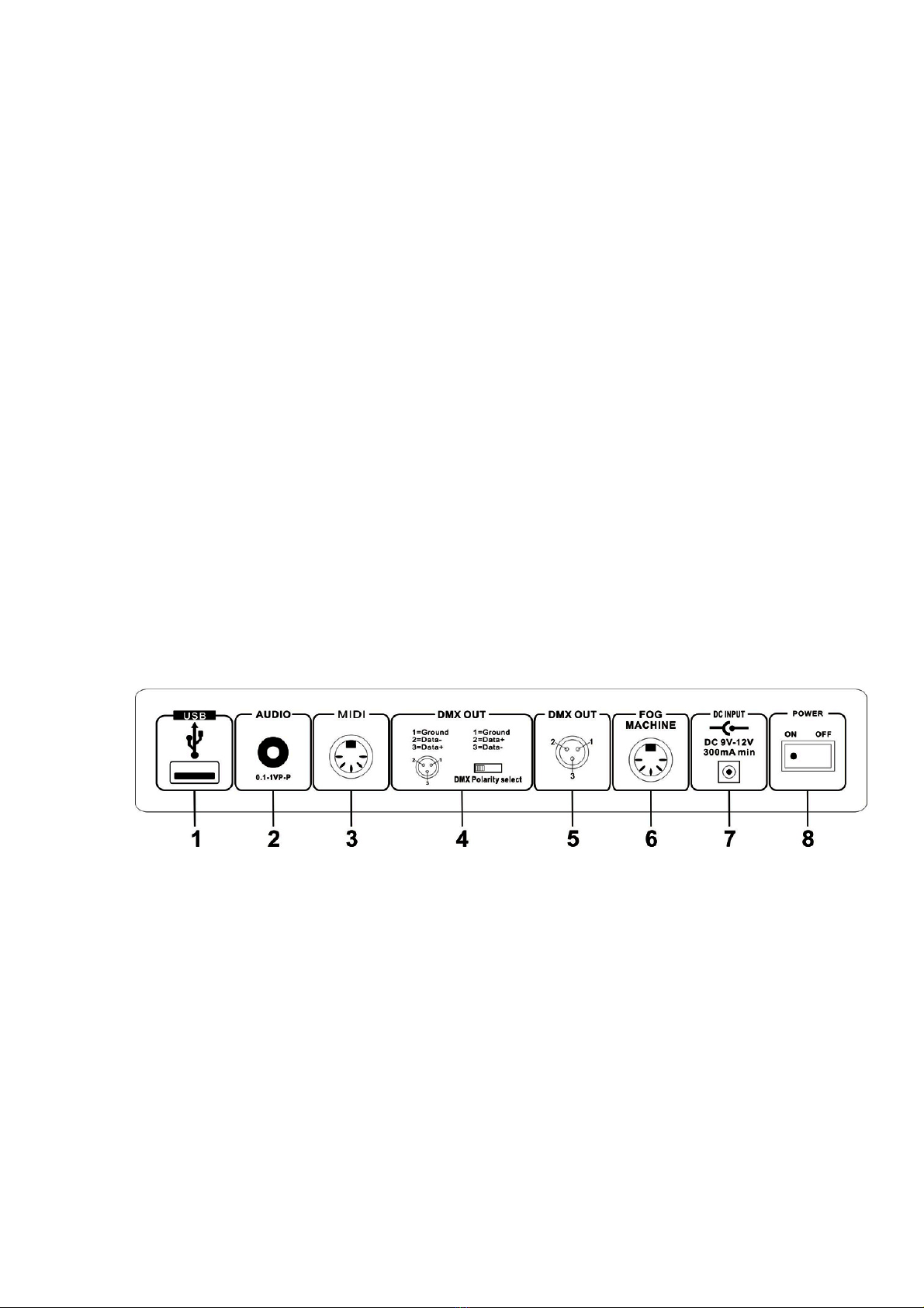
2. Back Side View
1.
..
.USB USB port
2.
..
.AUDIO IN 0.1…1 Vp-p
3.
..
.MIDI IN Receives MIDI data
4.
..
.DMX Polarity Select Used to select DMX polarity
5.
..
.DMX OUT DMX SINGAL OUTPUT
6.
..
.FOG MACHINE Connector to plug in the Fog Machine
7.
..
.DC INPUT DC 9 -12V, 300mA min
8.
..
.POWER Turn on/off the power

3. Fog machine diagram
4. Operation Guide
General:
This unit allows you to program 12 scanners of 16 DMX channels, 30 banks of 8
programmable scenes, 6 chases of 240 programmed scenes using 8 faders and
other function buttons. Data will be dumped on U disk and software promotion by
USB port ,also has RDX function ,remote DMX address.
Display Information
The LCD Display contains a maximum of 2x8 characters
LCD Display Message
CHASE5 Chase 5 is activated.
STEP006 The 6th step of a chase
DATA 168 DMX numerical value(000-255)
WT:2M18S The current Wait Time is 2 minute and 18 seconds
TP:5.58S The time of the last two taps is 558 seconds
FT:11.6S Fade Time is 11.6 seconds
ASS 07 08 Assign DMX channels 7 and 8
RES 02 03 Reverse DMX Channels 2 and 3
SN6 Scene 6
BK 08 Bank 08
4.1 Program Enable
Press the Program button for three seconds to activate Program mode, the
LED near to this button lights indicating Program in active.
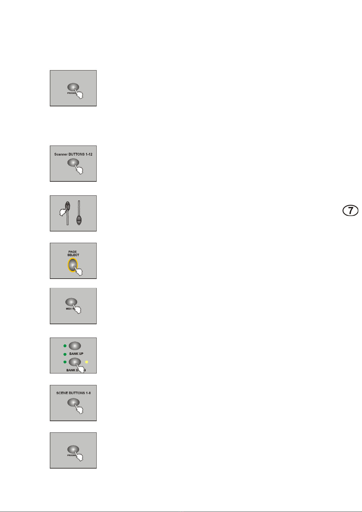
4.2 Programming Scenes
1. Enter Program mode
2. Press the Scanner button to turn on its fader control 1-12,
which is indicated by the lit LED
3. Move the faders to select your desired dimmer intensity if you are using a
dimmer; You can also use the two jog wheels to control the Pan or Tilt
movement of the scanner
4. Change the DMX 1-8 or 9-16 channel by PAGE button
PAGE A indicated by the lit LED when 1-8 channel
PAGE B indicated by the lit LED when 9-16 channel
5. Once the scene is satisfactory, tap the MIDI/Rec button to program this
scene into memory;
6. Tap the Bank Up/Down button to select the bank you want to store your
scene into
7. Tap the Scene button 1-8 to store your scene, all LEDs indicated will
flicker expecting the 2 frog machines
8.Repeat steps 3-7 operation will edit other effect
9. If you don't intend to continue your programming,press and hold down
the Program button for three seconds to exit Program mode
EXAMPLE:
Program 8 scenes with channel 1-8 at full in sequence into bank 3 and assign
these scenes to scanner 1.
1. Program enable;
2. Tap the Scanner 1 button to turn on its fader control;
3. Change the DMX 1-8 or 9-16 channel by PAGE button, and push the scene effect;
4. Tap the MIDI/Rec button;
5. Select bank 3 using Bank Up/Down button;
6. Tap the Scene 1-8 button to store the scene;
7. Repeat steps 3-6 and store other 7 scene;
8. Tap the Scanner 1 button again to turn off its fader control;
9. Press the Program button for 3 seconds to exit Programming mode
4.2.1 Scene Editing
1. Program enable;
2. Tap the Bank Up/Down button to select the bank that contains the
scene you wish to edit;
3. Select the scene you want to edit by tapping its Scene button;
4. Use the Faders or jog wheels to make your desired adjustments;
5. Once you've made your changes, tap the MIDI/Rec button;
6. Tap the Scene button that corresponds to the scene you're editing. This
will overwrite the exited scene.
NOTE:
Be sure to select the same scene in steps 3 and 6, otherwise you may accidentally record over
an exited scene.

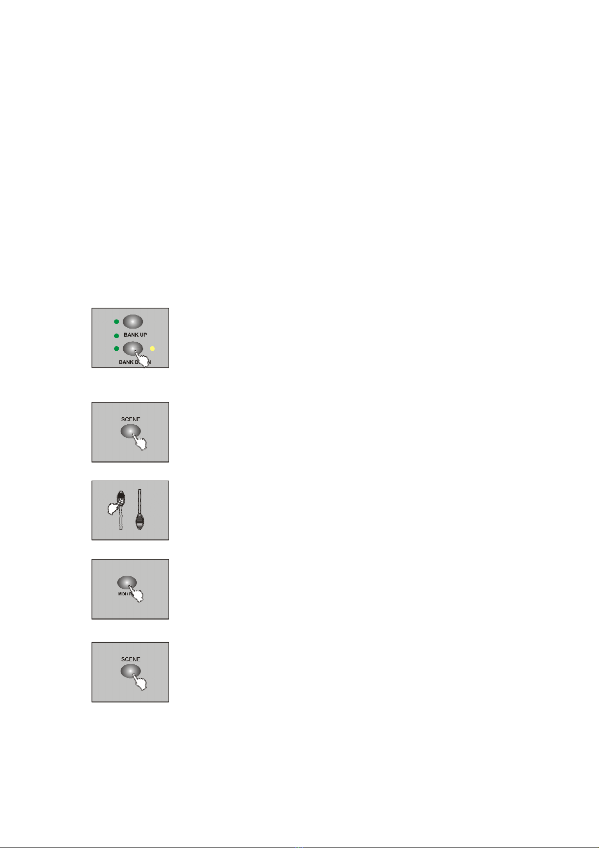
4.2.2 Scene copy
1. Program enable;
2. Tap the Bank Up/Down button to select the bank that contains the
scene you wish to edit;
3. Select the scene you want to copy;
4. Tap the Bank Up/Down button to select the bank that contains
the scene you wish to copy;
5. Tap the MIDI/Rec button;
6. ap the SCENE button, all LEDs will flicker ,copy finished.
4.2.3 Delete a scene
1. Program enable;
2. Tap the Bank Up/Down button to select the bank that
contains the scene you wish to delete;
3. Press and hold down the Auto/Del button. Tap the
Chase button which you want to delete the scene;
4. LEDS will flicker ,delete finished.
4.2.4 Delete a scene
This should be reset the controller again.
1. Turn off the power;
2. With the power off, press and hold down the Auto/Del and Bank
Down buttons at the same time,about 2 seconds ,all the leds will
flicker;
3. After the leds flicker,all the scenes will delete.
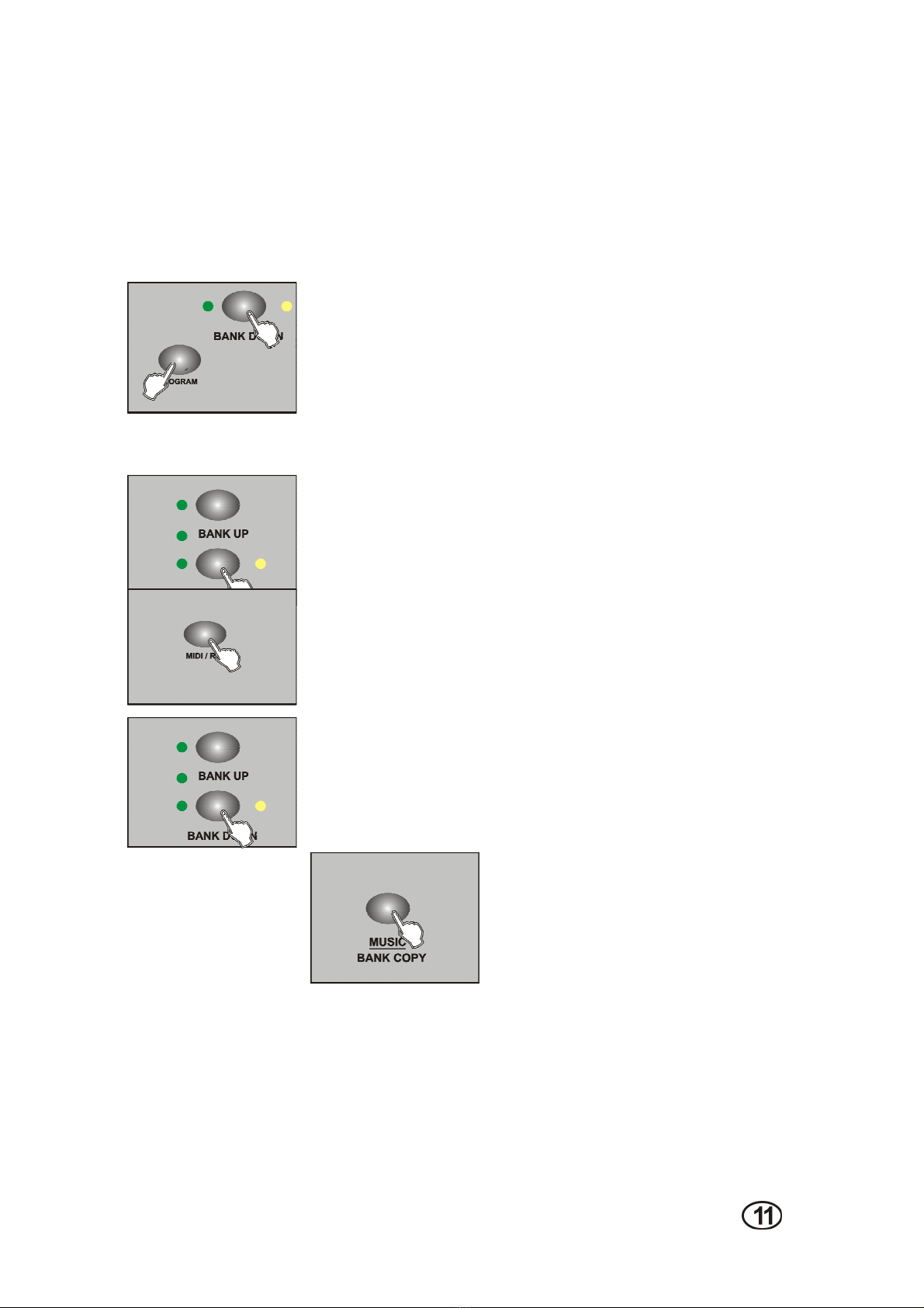
4.2.5 BANK copy
1. Program enable;
2. Tap the Bank UP/DOWN select the bank which needed copy;
3. Tap the MID/REC;
4. Tap the BANK UP/DOWN select the address which BANK copy
needed;
5. Tap the MUSIC/BANK COPY button,all the leds will
flicker ,finish the copy
6. Press and hold on the program about 3 seconds then exit the
programming.
4.2.6
Lamps copy
Copy one present lamps manual effect to another
1. Press the copy SCANNER button;
2. Tap the copy SCANNER button again,2 lamps
the output effect are the same .
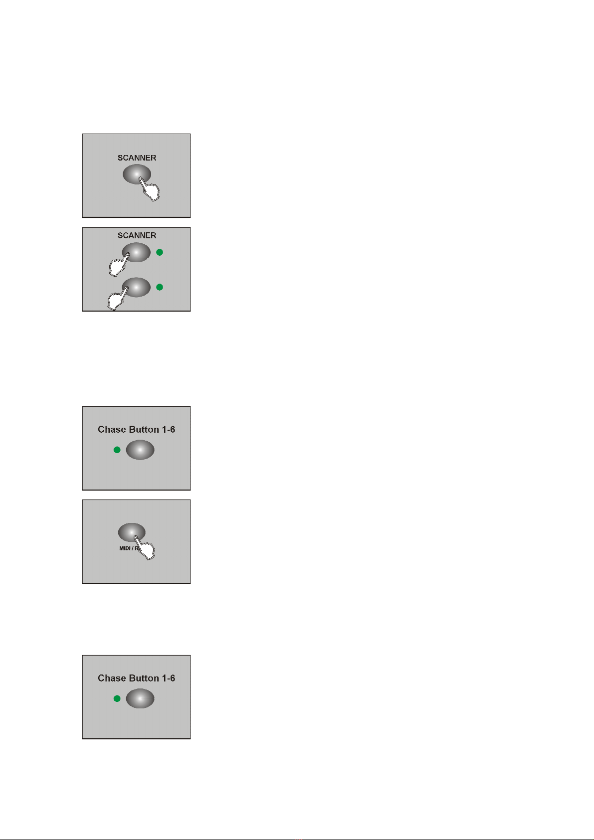
4.3 Editing program
Just can edit the program after edit the scene,because program can use 30 scene of the
bank,each edit can edit 240 steps at most .
1. Program enable;
2. Select one of the chase button 1-6;
3. Select one scene from the bank;;
4. Tap the MIDI/REC button,all the leds flicker means enter the
program;
5. Repeat the step 3.4,can edit 240 steps at most;
6. Tap an hold on PROGRAM about 3 seconds will exit the
program.
4.3.1 Edit the scene to program one time from the bank
1. Program enable;
2.Select one chase button 1-6;
3. Select the bank by BANK UP/DOWN;
4. Tap MUSIC/BANK to copy;
5. Tap MID/REC button,all the leds flicker ;8 scenes add to
program (if the bank is empty for scene ,otherwise will not );
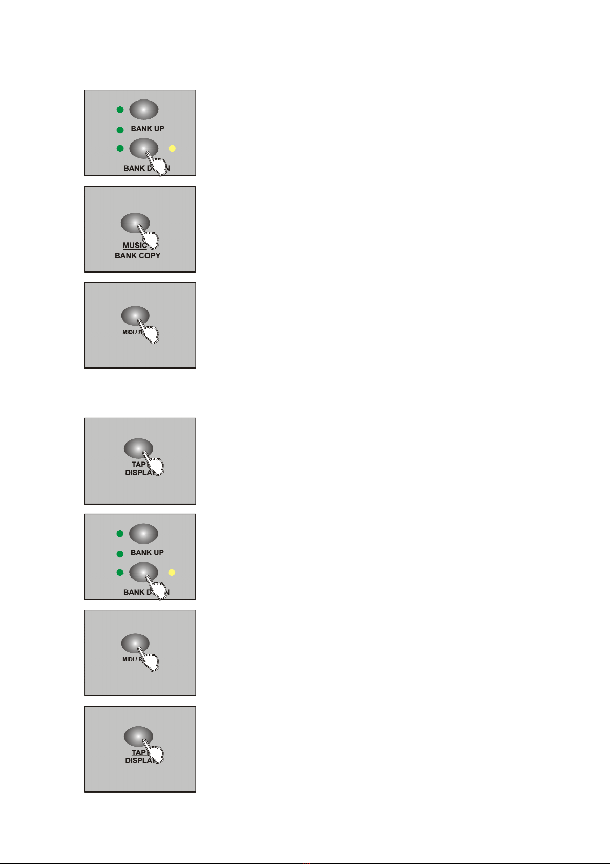
4.3.2 Add one step to the program
1. Program enable;
2. Select program;
3. Press the TAP button,LED switch to the present program ;
4. Tap the BANK UP/DOWN button to select the place which
will needed ;
5. Tap MIDI/REC ,make sure the added step;
6. Press the TAP button,switch to the LED BANK and SCENE;
7. Tap bank up/down ,select the added scene;

8. Tap the MIDI/REC button,all the leds flicker means the scene add
to the program.
TIPS:
If you want to insert one step between 3 and Switch to the 3 step by BANK
UP/DOWN ,press MIDI/REC button ,LED display ‘’STEP 004’’;
Notice:
Press Tap button ,change LED display mode (BANK mode and Step mode ).
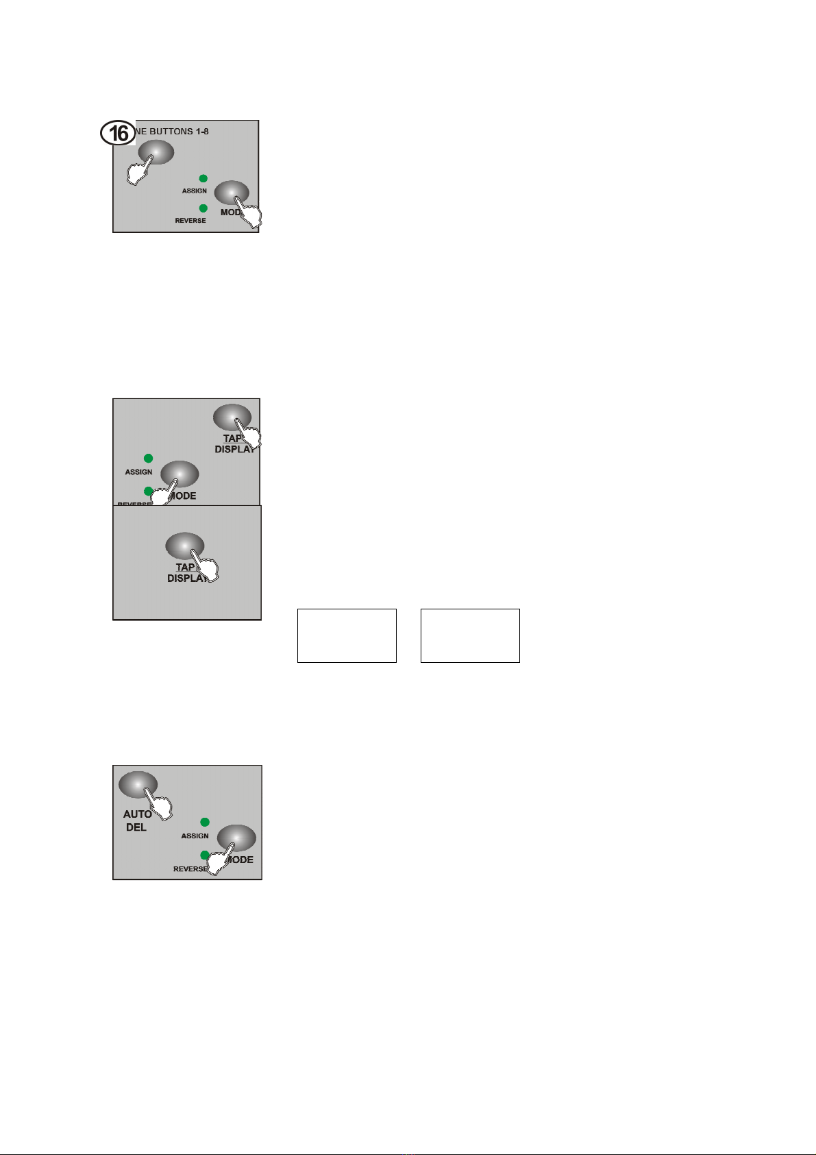
4.3.3 Delete one program step
1. Program enable;
2. Select the delete program;
3. Tap the TAP button LCD will display the present step
4. Tap the BANK UP/DOWN button,select the step which needed
delete;
5.Tap AUTO/DEL button ,delete LED display present step,all the
LEDS flicker ,delete succeed.
4.3.4 Delete one program
1. Program enable;
2. Open the program which needed delete;
3. Press and hold on AUTO/DEL button,tap the deleted program
again,all the LEDS flicker means program delete.

4-3.5 Delete all the program.
Need to reset the controller.
1.Turn off the power;
2. Press and hold on the AUTO/DEL and BANK DOWN at the
same time,turn on the power ,after about 2 seconds all the
LEDS flicker;
3. All the LEDS stop to flicker , all the program delete.
4.4 Channel assign and reverse
Press Mode and Fine button at the same time can switch assign and revise
mode
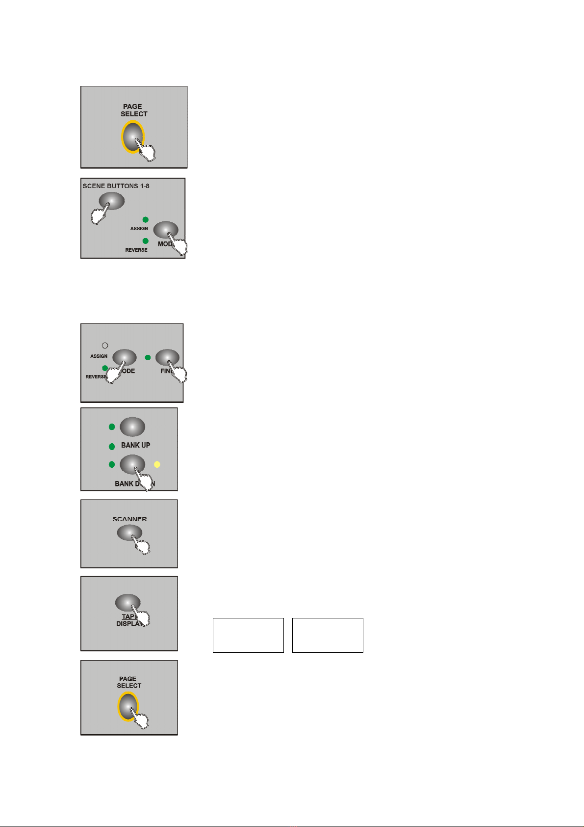
4.4.1 Channel Assign
1. Program enable;
2. Press abd hold on Mode and Fine button ,Reverse LED
indicating light up,enable reverse mode ,hold on this 2 button at the
same time againswitch to the assign mode ,Assign LED indicating
light up;
3. Tap the Bank Up/Down button select Pan or Tilt assign ,Relevant
LED indicating light up;
4. Select SCANNER button which needed assign lamp ;
5. Tap the TAP button set up the light 8 channel or 16 channel
mode;
ASSXX XX
X/Y 08C
H
ASSXX XX
X/Y 16CH
6. Page select channel located page (PAGE A/B);
7. Press and hold on Mode button firstly,then tap the
relevant assign SCENE BUTTON 1-8 button,all the
indicating flicker ,assign succeed,(this time SCENE 1
BUTTON correspond DMX channel 1 ,SCENE 2
button correspond DMX channel 2 ,and so on );
8. Repeat operate step 3-7,assign other SCANNER ,under
channel 8 mode ,12 lights can assign 48 DMX channel
at most ;under channel 16 mode ,12 lights can assign 24
DMX channel at most .
4.4.2 Reverse channel
1. Program enable;
2. Press and hold on the Mode and Fine button at the same
time ,Reverse LED indicating light up ,enable reverse mode;
3. Select Pan or Tilt reverse ,relevant by bank Up/Down button,LED
indicating light up;
4. Select SCANER button which needed assign;
5. Tap the TAP button setup the 8 channel or 16 channel mode;
6. Page select channel located page (PAGE A/B);
RECXX XX
X/Y 08CH
RECXX XX
X/Y 16CH
7. Press and hold on Mode button firstly,then tap the
relevant assign SCENE BUTTON 1-8 button, all the
indicating flicker ,assign succeed,(this time SCENE 1
BUTTON correspond DMX channel 1 ,SCENE 2
button correspond DMX channel 2 ,and so on );
8. Repeat operate step 3-7,assign other SCANNER ,
under channel 8 mode ,12 lights can assign 48 DMX channel
at most ;under channel 16 mode ,12 lights can assign 24
DMX channel at most .
4.4.3 Glide mode select
1. Turn off the power;
2. Press and hold on the MODE and TAP button at the same
time,then turn on the power ,about 2 seconds enable the slide mode
3.Tap the TAP button wsitch to slide mode (all the DMX chanel
slide or just X/Y channel slide )
LCD display as follows :
4. Press and hold on MODE and TAP button again at the same time .,all the indicating
flicker,save succeed ,controller auto reset up.
4.4.4 Delete channel assign and reverse
1.Program enable;
2. Press the MODE and FINE button at the same time ,select
assign and reverse;
3.Tap SCANNER 1-12 select lamps;
4.Press AUTO /DEL button,then tap mode button,can delete channel assign and reverse.
4.4.5 Delete all
the chanle assign and reverse
ALL CH
FD TIME
ONLY X/Y
FD TIME

1.Turn off the power ;
2. Press and hold on AUTO and MODE ;
3. LEDS indicating stop flicker,controller will be auto reset up ,all
the assign and reverse will be deleted.
4.4.6 Examine the assign and reverse
1. Press and hold on MODE and FINE ,enter to
examine reverse mode;
2. Press and hold on MODE and FINE button again,
examine assign mode;
3. Tap SCANNER 1-12 ,select the light which
needed examine,LCD will display assign and
reverse information.
4.4.7 Staring up display information
1. Turn off the power ;
2. Press and hold on SCANNER 6 and 12 button at
the same time ,open the controller power about
2 seconds ,SCANNER 6 and 12 LEDs indicating,
enter set up condition;
3.Tap SCANNER 6 and 12 adjust the location of
the LCD cursor;
4.Select character by BANK UUP/DOWN button
5. Repeat step 3 and 4 ,set up needed information
6.Press SCANNER 6 and 12 button at the same time , all the
indicating light flicker ,save it ,controller auto reset up

4.5 Operate scene
4.5.1 AUTO mode
1. Controller opened will enter Manual condition every time;
2. MANUAL CONDITION indicating light on;
3.Tap BANK UP/DOWN button ,select the bank which the
scene located;
4. Tap SCENE 1-8 ,open the scene.
4.5.2 AUTO mode
Under AUTO mode ,the scene of the bank will circular flow in turn.
1. Tap AUTO/DEL ,AUTO indicating light on,enter
AUTO mode;
2.Tap BANK UP/DOWN ,switch bank ,select scene;
3.Adjust WAIT TIME puncher (or Tap button ) and FADE
TIME puncher to control the time of scene;
4.Press AUTO/DEL button ,AUTO indicating light off,back
to Manual mode.
Notice:
Tap TAP button take the time ,the two TAP distant time as the scene run time.
4.5.3 Voice control
Table of contents
Other Showlite Dj Equipment manuals

Showlite
Showlite LED MMB-100BT User manual

Showlite
Showlite SF-100 User manual

Showlite
Showlite LDO-10 MKII FS User manual

Showlite
Showlite SPS-121 User manual

Showlite
Showlite SM-600 User manual

Showlite
Showlite DS-1500DMX User manual

Showlite
Showlite Party Rebel E27B-5W User manual

Showlite
Showlite 00036730 User manual

Showlite
Showlite PBM-9 User manual

Showlite
Showlite UL-9 User manual


